Concept : “Frenzy Jump”
For my project, I decided to create a simple game on p5js.
Idea of the game : For the Arduino part, there are two buttons one functions as a “restart button” to restart the game after losing, and the other functions as an action button to make the player “triangle” to jump.
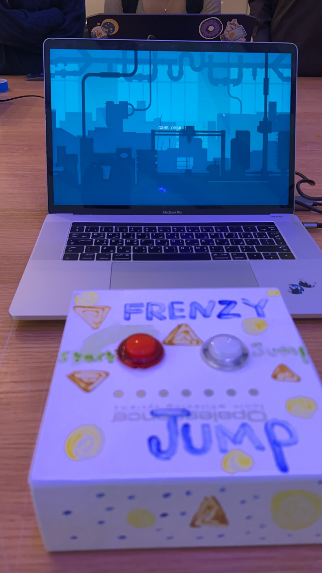
The game starts with a background that says “Press red button to start and white button to jump”, upon pressing the red red button the screen will start the game with the player being a “triangle”, as per instruction at the start the user will press the white button for the player to jump over rectangular obstacles, throughout the game there are golden “coins” which are ellipses created to gain extra points on the scoreboard that can be seen on the top right corner of the game. When the user fails with jumping over a certain obstacle, the screen will give you a message saying “GAMEOVER” . To restart the game, the user should press on the red button, and the game will automatically start again.
Inspiration:
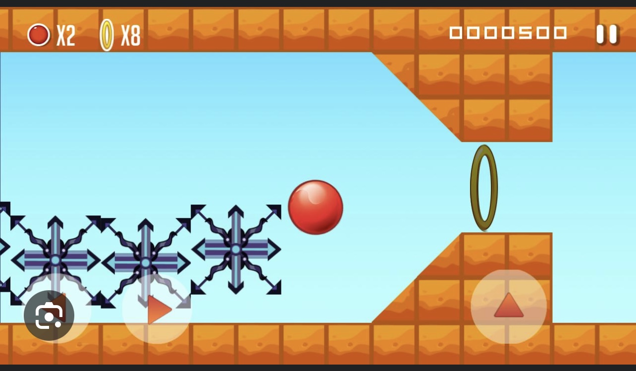
I got this idea from a game i think most people have played once in their life, view the image below :
Components:
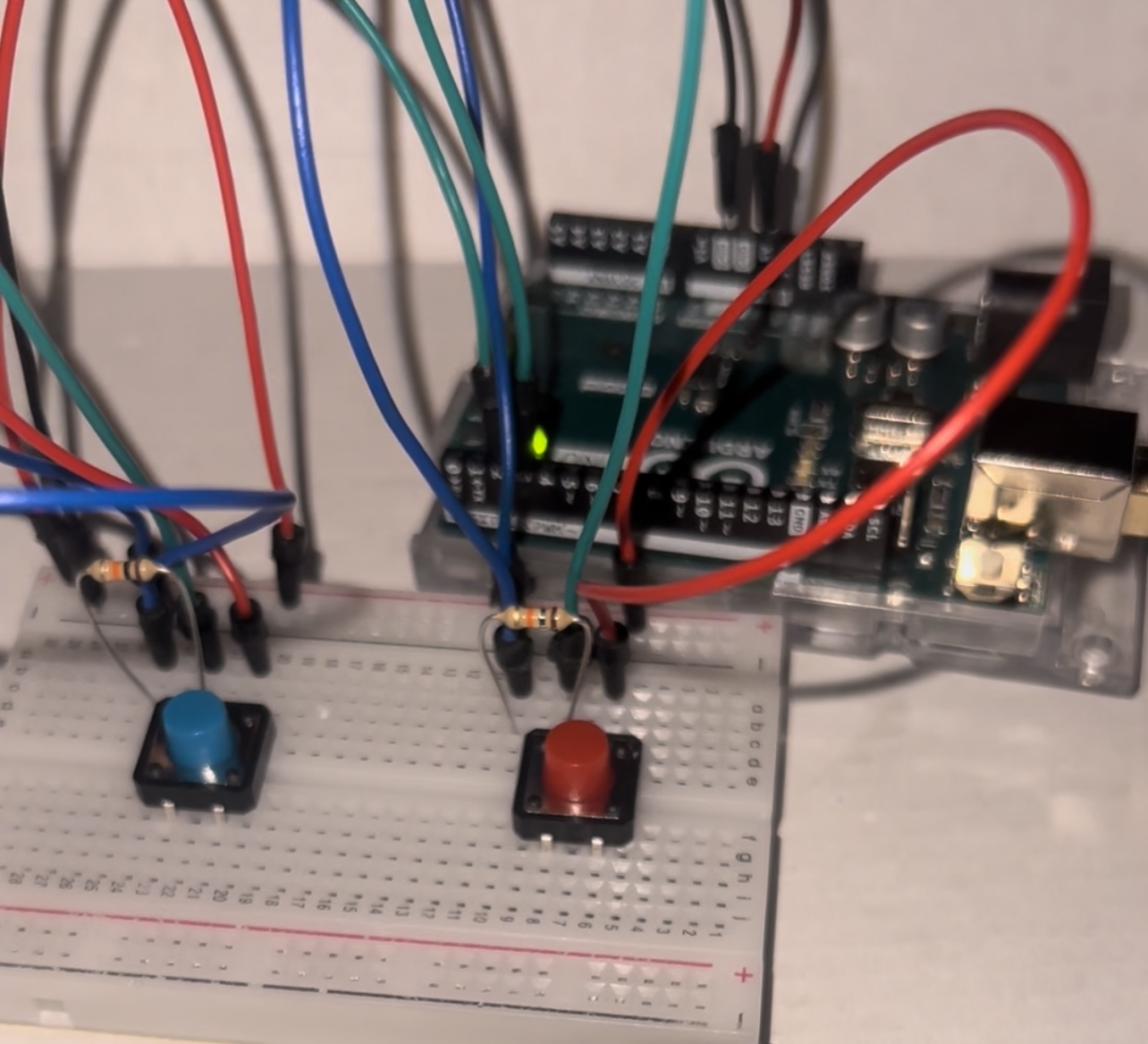
- 2 LED buttons , red and white
- Resistors are built in the led button i did not use the LED side of the button therefore i did not add extra resistors on the breadboard
- 6 jumper wires
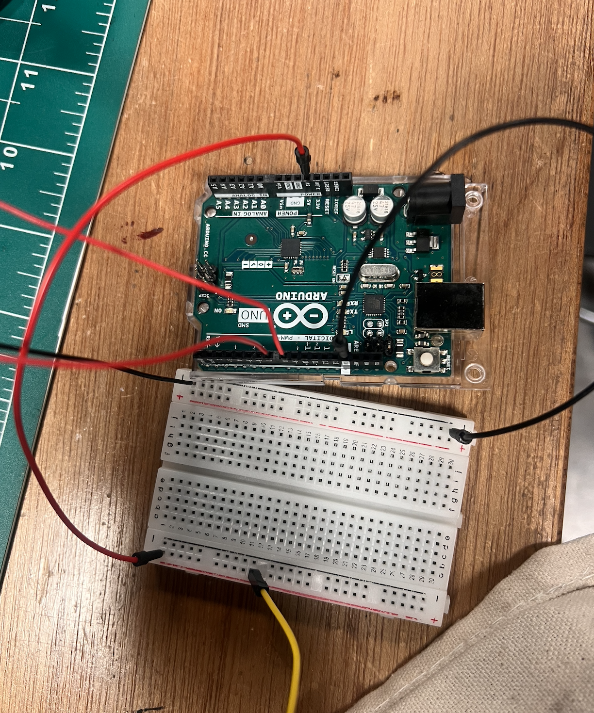
Controller:
Prototype 1 :
Final prototype :
User Experience and Gameplay :

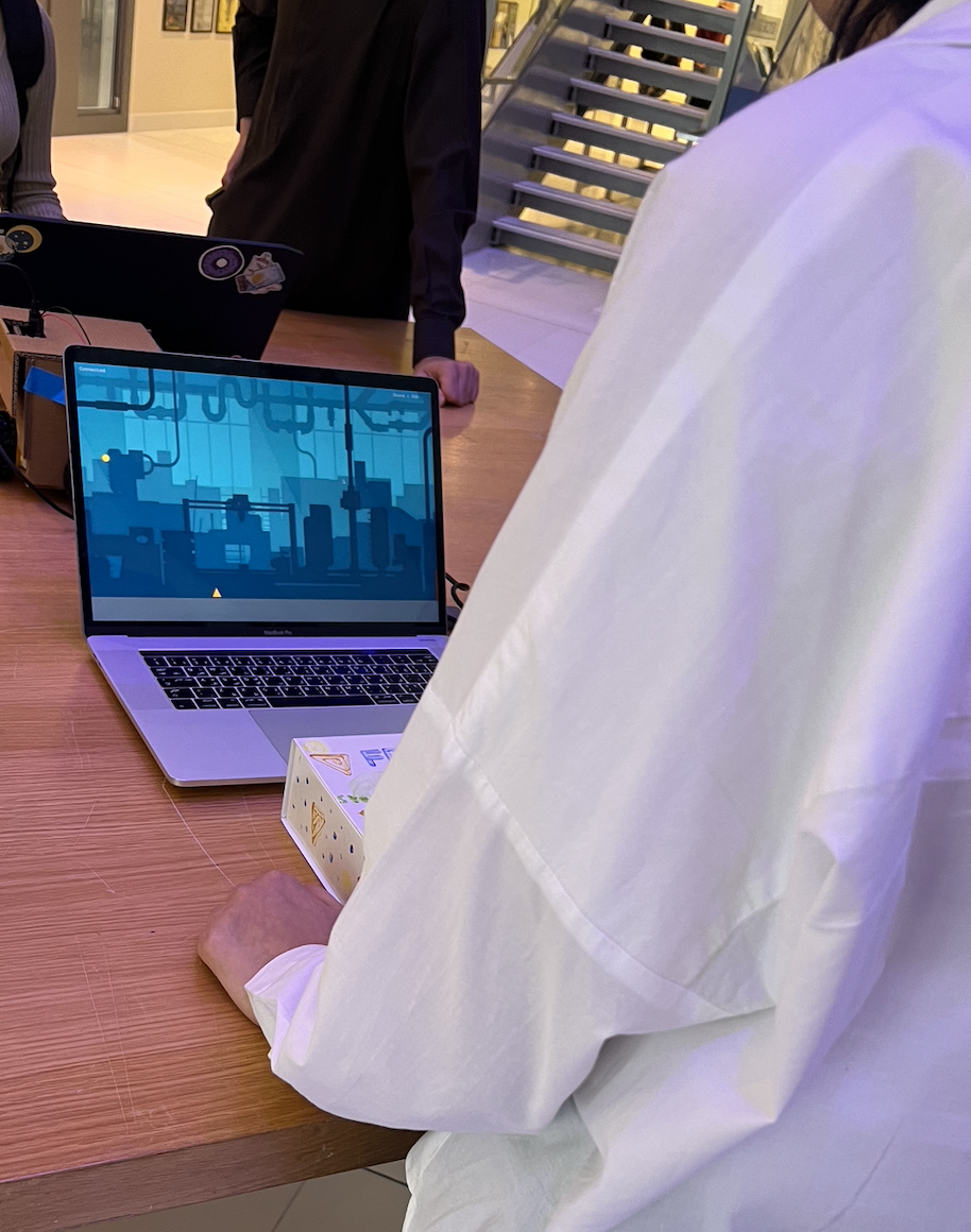
Embedded sketch :
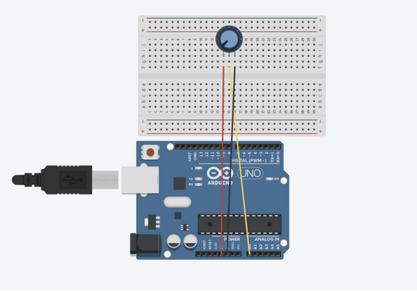
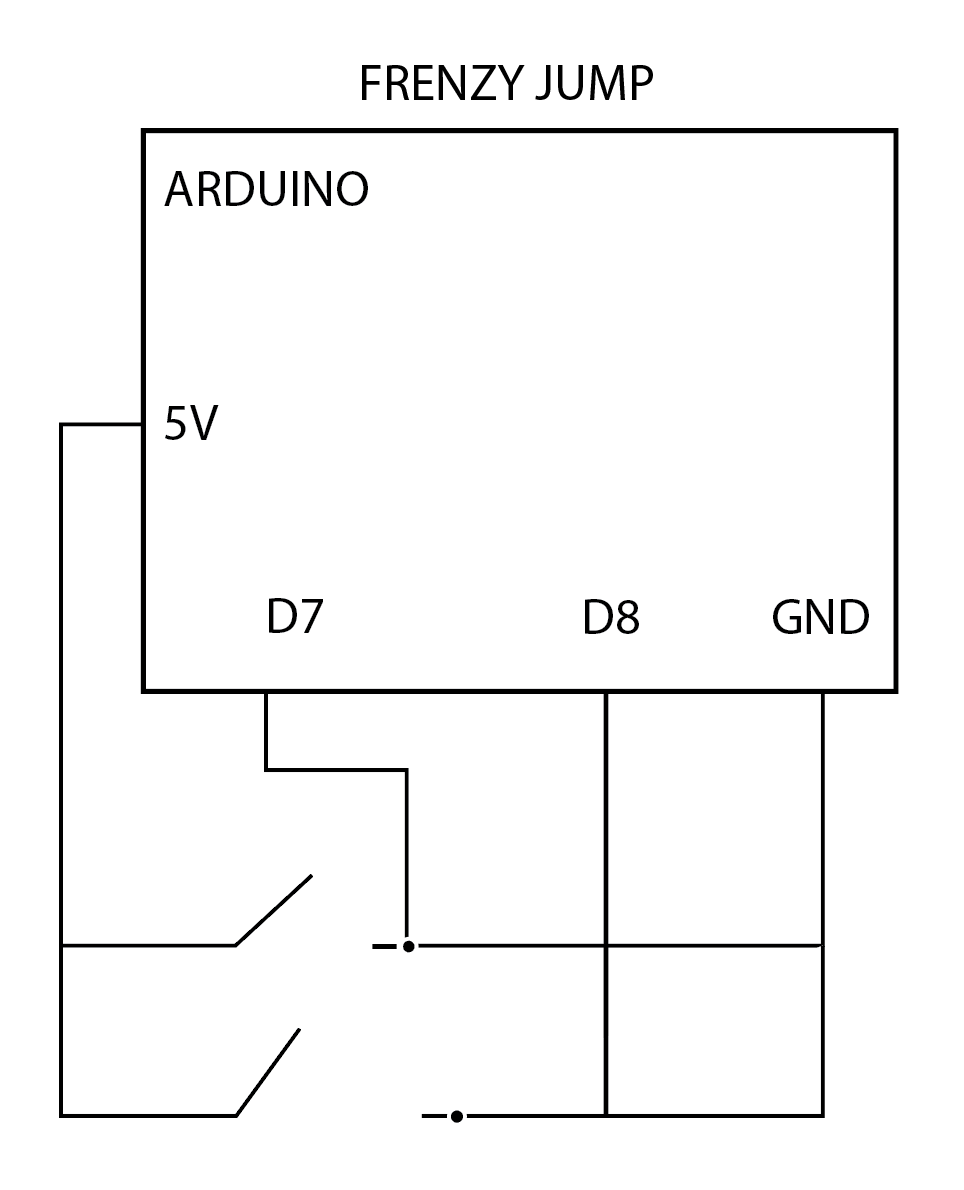
Schematics:
its probably incorrect but i tried
Testing in Arduino Serial Port :
References :
P5js code : https://editor.p5js.org/mka413/sketches/kwS7JN7Wh
The code that made me proud: I cant choose only one part, because if i must say i am very proud of myself, and what i have achieved this semester, to knowing nothing about coding to creating this simple yet successful simple game. What about difficulties? i will talk about that later on in my blog post.
How does Arduino work with p5js? :
Starting with the code in Arduino after I’ve set up the connections in the controller i wrote the lines of code that we were taught in class about Serial Data communication and put in the corresponding pin numbers for the “restart” and “action”(jump) buttons also i used the Function (pinMode) as an input for my pins , and the function digitalRead for my pins to be read in values of :false or true lastly, i used the Serial.println to send/print serial data to the port as seen in the lines of code below :
int RedButton= 7;
int whiteButton= 8;
bool isActionButtonPressed = false; //start with false as the buttons are not pressed
bool isRestartButtonPressed = false;


void setup() {
  Serial.begin(9600); // setting the baud rate for serial data communication

  pinMode(RedButton, INPUT_PULLUP);
  pinMode(whiteButton, INPUT_PULLUP);


}

void loop() {
//sending signals whether the buttons are pressed and giving true or false statements to confirm
  if(digitalRead(RedButton)) {
    if(!isActionButtonPressed) {

      eventActionButtonPressed(RedButton);

      isActionButtonPressed = true;
    }
  }
  else {
    if(isActionButtonPressed) {

      eventActionButtonReleased(RedButton);

      isActionButtonPressed = false;
    }
  }

  if(digitalRead(whiteButton)) {
    if(!isRestartButtonPressed) {

      eventRestartButtonPressed(whiteButton);

      isRestartButtonPressed = true;
    }
  }
  else {
    if(isRestartButtonPressed) {

      eventRestartButtonReleased(whiteButton);

      isRestartButtonPressed = false; //// printing data to the serial port void eventActionButtonPressed(int pin)
    }
  }

}

// printing data to the serial port void eventActionButtonPressed(int pin)
void eventActionButtonPressed(int pin) {
  Serial.println(String(pin) + ":pressed");
}

void eventActionButtonReleased(int pin) {
  Serial.println(String(pin) + ":released");
}

void eventRestartButtonPressed(int pin) {
  Serial.println(String(pin) + ":pressed");
}

void eventRestartButtonReleased(int pin) {
  Serial.println(String(pin) + ":released");
}
After finishing up the Arduino code, now its time to begin serial data communication in p5JS, with firstly adding the ready web serial file that was made available for us, then in the actual p5js sketch code i added these lines of code to make serial data communication work with Arduino IDE :
// Function to read serial data
function readSerial(data) {
  const pin = data.split(':')[0];
  const action = data.split(':')[1];

  console.log(data);

  if(pin == "7" && action == "pressed") {
    if(!player.isJumping) {
      player.isJumping = true;
      player.timeJump = millis();
      player.forceY = -10;
    }
  }

   if(pin == "8" && action == "pressed") {
      if(!gameStarted) {
        gameStarted = true;
      }

     if(gameover) {
        gameover = false;
        score = 0;
        player.posX = width / 3;

        for(const o of obstacles) o.posX += width;

      }
    }

}

// Function to handle key presses
function keyPressed() {
  // If space is pressed, set up serial communication
  if(key == " ") {
    setUpSerial();
  }

  // press f to play the game in fullscreen
  if(key == 'f') {
    const fs = fullscreen();
    fullscreen(!fs);
  }
}
// this function is called every time the browser window is resized
function windowResized() {
  resizeCanvas(windowWidth, windowHeight);
}
Difficulties :
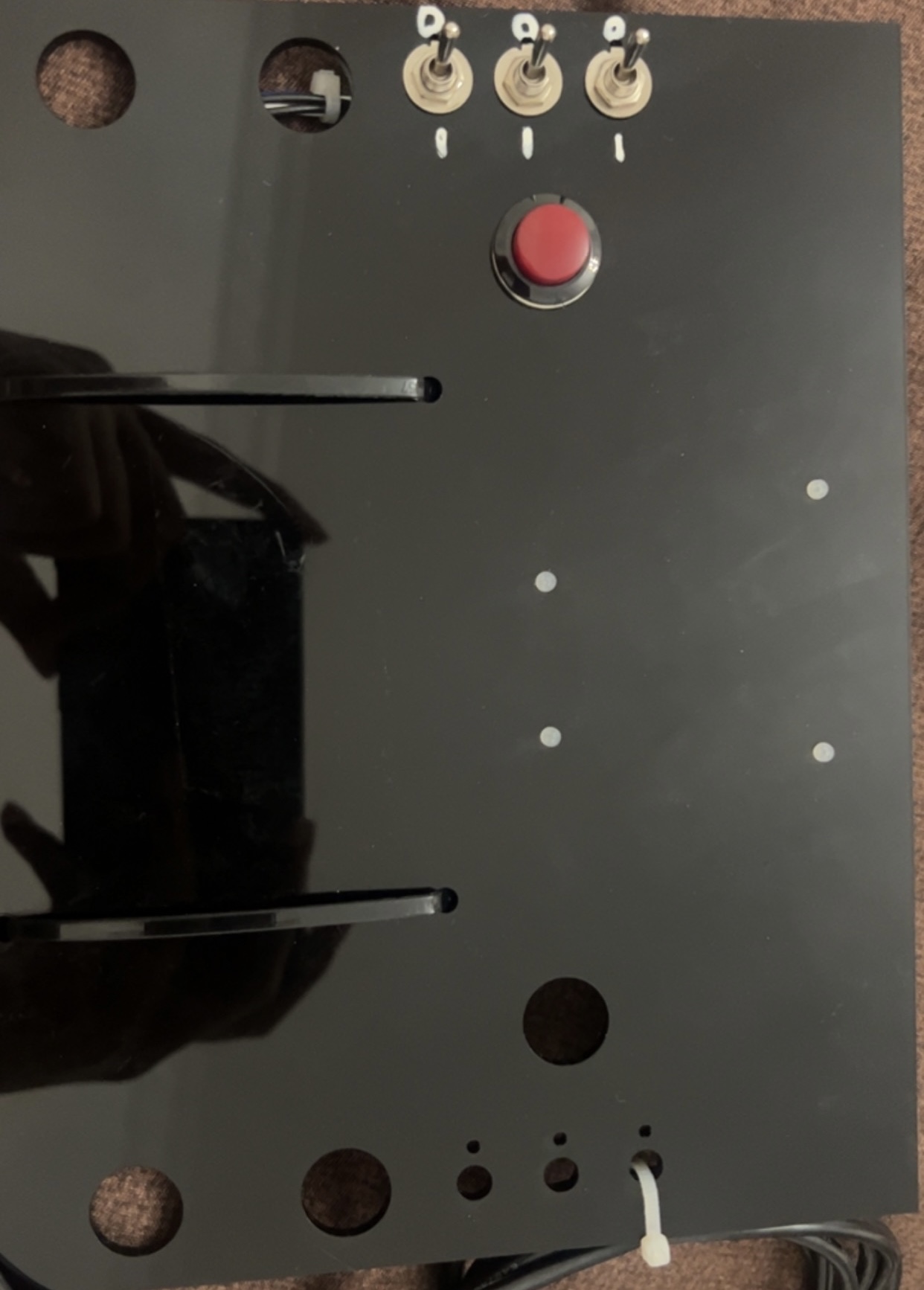
I had a lot of difficulties in making my initial acrylic controller to work, which i firstly thought there must be a problem with my code, after numerous attempts in trying to make the button and flip switch to work, i gathered that the connections were not correct or they have been short circuited. Thinking fast, i created the usual breadboard connections with push button switches that worked instantly when uploading the code to my arduino. Also i had trouble with making the serial data communication to work on p5js where the browser would not pop up so i can make the connection to the serial port, which was nerve wrecking but i eventually after trial and error i got it to work perfectly.
My initial Conntroller :
Changes for the future:
I would really liked to have my first controller to work, it looked really cool, and would have fit in more with my game and its aesthetic. Still i would like to advance more in my coding skills to create something much more complex. Adding more difficult obstacles, and increasing the speed the longer you play, with a high score page also.