Final Project

Hassan, Aaron, Majid.

CONCEPT

How would someone virtually learn how complicated it is to drive a car? Would teaching someone how to drive a car virtually save a lot of money and decrease potential accidents associated with driving? These questions inspired our project, which is to create a remote-controlled car that can be controlled using hand gestures (that imitate the driving steering wheel movements), specifically by tracking the user’s hand position and a foot pedal. The foot pedal will be used to control the acceleration, braking, and reversing. We will achieve all these by integrating a P5JS tracking system into the car, which will interpret the user’s hand gestures and translate them into commands that control the car’s movements. The hand gestures and pedal control will be synced together via two serial ports that will communicate with the microcontroller of the car.

Experience

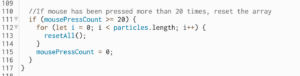
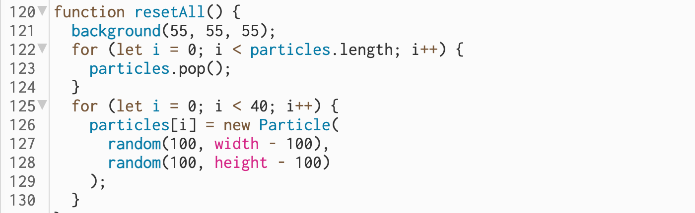
The entire concept is not based only on a driving experience. We introduce a racing experience by creating a race circuit. The idea is for a user to complete a lap in the fastest time possible. Before you begin the experience, you can view the leaderboard. After your time has been recorded, a pop-up appears for you to input your name to be added to the leaderboard. For this, we created a new user interface on a separate laptop. This laptop powers an Arduino circuit connection which features an ultrasonic sensor. The ultrasonic sensor checks when the car has crossed the start line and begins a timer, and detects when the user ends the circuit. After this, it records the time it took a user to complete the track and sends this data to the leaderboard.

This piece of code is how we’re able to load and show the leaderboard.

function loadScores() {
let storedScores = getItem("leaderboard");
if (storedScores) {
highscores = storedScores;
console.log("Highscores loaded:", highscores);
} else {
console.log("No highscores found.");
}
}

function saveScores() {
// make changes to the highscores array here...
storeItem("leaderboard", highscores);
console.log("Highscores saved:", highscores);
}


IMPLEMENTATION(The Car & Foot Pedal)

We first built the remote-controlled car using an Arduino Uno board, a servo motor, a Motor Shield 4 Channel L293D, an ultrasonic sensor, 4 DC motors, and other peripheral components. Using the Motor Shield 4 Channel L293D decreased numerous wired connections and allowed us space on the board on which we mounted all other components. After, we created a new Arduino circuit connection to use the foot pedal. 

The foot pedal sends signals to the car by rotating a potentiometer whenever the pedal is engaged. The potentiometer value is converted into forward/backward movement before it reaches p5.js via serial communication.

P5/Arduino Communication

At first, a handshake is established to ensure communication exists before proceeding with the program:

//////////////VarCar/////
// Define Serial port
let serial;
let keyVal;
//////////////////////////
const HANDTRACKW = 432;
const HANDTRACKH = 34;

const VIDEOW = 320;
const VIDEOH = 240;

const XINC = 5;
const CLR = "rgba(200, 63, 84, 0.5)";

let smooth = false;
let recentXs = [];
let numXs = 0;

// Posenet variables
let video;
let poseNet;

// Variables to hold poses
let myPose = {};
let myRHand;

let movement;
////////////////////////

let Acceleration = 0;
let Brake = 0;
let data1 = 0;
let data2 = 0;

let s2_comp=false;

function setup() {
// Create a canvas
//createCanvas(400, 400);

// // Open Serial port
// serial = new p5.SerialPort();
// serial.open("COM3"); // Replace with the correct port for your Arduino board
// serial.on("open", serialReady);

///////////////////////////
// Create p5 canvas

The Hand Gestures

Two resources that helped detect the user’s hand position were PoseNet and Teachable Machine. We used these two resources to create a camera tracking system which was then programmed to interpret specific hand gestures, such as moving the hand right or left to move the car in those directions. This aspect of our code handles the hand tracking and gestures.

if (myPose) {
try {
// Get right hand from pose
myRHand = getHand(myPose, false);
myRHand = mapHand(myRHand);

const rangeLeft2 = [0, 0.2 * HANDTRACKW];
const rangeLeft1 = [0.2 * HANDTRACKW, 0.4 * HANDTRACKW];
const rangeCenter = [0.4 * HANDTRACKW, 0.6 * HANDTRACKW];
const rangeRight1 = [0.6 * HANDTRACKW, 0.8 * HANDTRACKW];
const rangeRight2 = [0.8 * HANDTRACKW, HANDTRACKW];

// Check which range the hand is in and print out the corresponding data
if (myRHand.x >= rangeLeft2[0] && myRHand.x < rangeLeft2[1]) {
print("LEFT2");
movement = -1;
} else if (myRHand.x >= rangeLeft1[0] && myRHand.x < rangeLeft1[1]) {
print("LEFT1");
movement = -0.5;
} else if (myRHand.x >= rangeCenter[0] && myRHand.x < rangeCenter[1]) {
print("CENTER");
movement = 0;
} else if (myRHand.x >= rangeRight1[0] && myRHand.x < rangeRight1[1]) {
print("RIGHT1");
movement = 0.5;
} else if (myRHand.x >= rangeRight2[0] && myRHand.x <= rangeRight2[1]) {
print("RIGHT2");
movement = 1;
}
// Draw hand
push();
const offsetX = (width - HANDTRACKW) / 2;
const offsetY = (height - HANDTRACKH) / 2;
translate(offsetX, offsetY);
noStroke();
fill(CLR);
ellipse(myRHand.x, HANDTRACKH / 2, 50);
pop();
} catch (err) {
print("Right Hand not Detected");
}
print(keyVal)


The Final Result & Car Control

The final result was an integrated system consisting of the car, the pedal, and gesture control in P5.JS. When the code is run in p5.js, the camera detects a user’s hand position and translates it into movement commands for the car.

The entire code for controlling the car.

//////////////VarCar/////
// Define Serial port
let serial;
let keyVal;
//////////////////////////
const HANDTRACKW = 432;
const HANDTRACKH = 34;

const VIDEOW = 320;
const VIDEOH = 240;

const XINC = 5;
const CLR = "rgba(200, 63, 84, 0.5)";

let smooth = false;
let recentXs = [];
let numXs = 0;

// Posenet variables
let video;
let poseNet;

// Variables to hold poses
let myPose = {};
let myRHand;

let movement;
////////////////////////

let Acceleration = 0;
let Brake = 0;
let data1 = 0;
let data2 = 0;

let s2_comp=false;

function setup() {
// Create a canvas
//createCanvas(400, 400);

// // Open Serial port
// serial = new p5.SerialPort();
// serial.open("COM3"); // Replace with the correct port for your Arduino board
// serial.on("open", serialReady);

///////////////////////////
// Create p5 canvas
createCanvas(600, 600);
rectMode(CENTER);

// Create webcam capture for posenet
video = createCapture(VIDEO);
video.size(VIDEOW, VIDEOH);
// Hide the webcam element, and just show the canvas
video.hide();

// Posenet option to make posenet mirror user
const options = {
flipHorizontal: true,
};

// Create poseNet to run on webcam and call 'modelReady' when model loaded
poseNet = ml5.poseNet(video, options, modelReady);

// Everytime we get a pose from posenet, call "getPose"
// and pass in the results
poseNet.on("pose", (results) => getPose(results));
}

function draw() {
// one value from Arduino controls the background's red color
//background(0, 255, 255);

/////////////////CAR///////
background(0);

strokeWeight(2);
stroke(100, 100, 0);
line(0.2 * HANDTRACKW, 0, 0.2 * HANDTRACKW, height);
line(0.4 * HANDTRACKW, 0, 0.4 * HANDTRACKW, height);
line(0.6 * HANDTRACKW, 0, 0.6 * HANDTRACKW, height);
line(0.8 * HANDTRACKW, 0, 0.8 * HANDTRACKW, height);
line(HANDTRACKW, 0, HANDTRACKW, height);
line(1.2 * HANDTRACKW, 0, 1.2 * HANDTRACKW, height);

if (myPose) {
try {
// Get right hand from pose
myRHand = getHand(myPose, false);
myRHand = mapHand(myRHand);

const rangeLeft2 = [0, 0.2 * HANDTRACKW];
const rangeLeft1 = [0.2 * HANDTRACKW, 0.4 * HANDTRACKW];
const rangeCenter = [0.4 * HANDTRACKW, 0.6 * HANDTRACKW];
const rangeRight1 = [0.6 * HANDTRACKW, 0.8 * HANDTRACKW];
const rangeRight2 = [0.8 * HANDTRACKW, HANDTRACKW];

// Check which range the hand is in and print out the corresponding data
if (myRHand.x >= rangeLeft2[0] && myRHand.x < rangeLeft2[1]) {
print("LEFT2");
movement = -1;
} else if (myRHand.x >= rangeLeft1[0] && myRHand.x < rangeLeft1[1]) {
print("LEFT1");
movement = -0.5;
} else if (myRHand.x >= rangeCenter[0] && myRHand.x < rangeCenter[1]) {
print("CENTER");
movement = 0;
} else if (myRHand.x >= rangeRight1[0] && myRHand.x < rangeRight1[1]) {
print("RIGHT1");
movement = 0.5;
} else if (myRHand.x >= rangeRight2[0] && myRHand.x <= rangeRight2[1]) {
print("RIGHT2");
movement = 1;
}
// Draw hand
push();
const offsetX = (width - HANDTRACKW) / 2;
const offsetY = (height - HANDTRACKH) / 2;
translate(offsetX, offsetY);
noStroke();
fill(CLR);
ellipse(myRHand.x, HANDTRACKH / 2, 50);
pop();
} catch (err) {
print("Right Hand not Detected");
}
print(keyVal)

//print(movement);
// print("here")
//print(writers);
}
//////////////////////////

if (!serialActive1 && !serialActive2) {
text("Press Space Bar to select Serial Port", 20, 30);
} else if (serialActive1 && serialActive2) {
text("Connected", 20, 30);

// Print the current values
text("Acceleration = " + str(Acceleration), 20, 50);
text("Brake = " + str(Brake), 20, 70);
mover();
}

}

function keyPressed() {
if (key == " ") {
// important to have in order to start the serial connection!!
setUpSerial1();
} else if (key == "x") {
// important to have in order to start the serial connection!!
setUpSerial2();
s2_comp=true
}
}

/////////////CAR/////////
function serialReady() {
// Send initial command to stop the car
serial.write("S",0);
print("serialrdy");
}

function mover() {
print("mover");

// Send commands to the car based wwon keyboard input
if (Acceleration==1) {
writeSerial('S',0);

//print(typeof msg1)

}else if (Brake==1) {
writeSerial('W',0);
}else if ( movement < 0) {
print("left")
writeSerial('A',0);
}else if ( movement > 0) {
print("right")

writeSerial('D',0);
}else if (movement== 0) {
print("stop");
writeSerial('B',0);
}
}

// When posenet model is ready, let us know!
function modelReady() {
console.log("Model Loaded");
}

// Function to get and send pose from posenet
function getPose(poses) {
// We're using single detection so we'll only have one pose
// which will be at [0] in the array
myPose = poses[0];
}

// Function to get hand out of the pose
function getHand(pose, mirror) {
// Return the wrist
return pose.pose.rightWrist;
}

// function mapHand(hand) {
//   let tempHand = {};
//   tempHand.x = map(hand.x, 0, VIDEOW, 0, HANDTRACKW);
//   tempHand.y = map(hand.y, 0, VIDEOH, 0, HANDTRACKH);

//   if (smooth) tempHand.x = averageX(tempHand.x);

//   return tempHand;
// }
function mapHand(hand) {
let tempHand = {};
// Only add hand.x to recentXs if the confidence score is greater than 0.5
if (hand.confidence > 0.2) {
tempHand.x = map(hand.x, 0, VIDEOW, 0, HANDTRACKW);

if (smooth) tempHand.x = averageX(tempHand.x);
}

tempHand.y = map(hand.y, 0, VIDEOH, 0, HANDTRACKH);

return tempHand;
}

function averageX(x) {
// the first time this runs we add the current x to the array n number of times
if (recentXs.length < 1) {
console.log("this should only run once");
for (let i = 0; i < numXs; i++) {
recentXs.push(x);
}
// if the number of frames to average is increased, add more to the array
} else if (recentXs.length < numXs) {
console.log("adding more xs");
const moreXs = numXs - recentXs.length;
for (let i = 0; i < moreXs; i++) {
recentXs.push(x);
}
// otherwise update only the most recent number
} else {
recentXs.shift(); // removes first item from array
recentXs.push(x); // adds new x to end of array
}

let sum = 0;
for (let i = 0; i < recentXs.length; i++) {
sum += recentXs[i];
}

// return the average x value
return sum / recentXs.length;
}

////////////////////////

// This function will be called by the web-serial library
// with each new *line* of data. The serial library reads
// the data until the newline and then gives it to us through
// this callback function
function readSerial(data) {
////////////////////////////////////
//READ FROM ARDUINO HERE
////////////////////////////////////

if (data != null) {
// print(data.value);
let fromArduino = data.value.split(",");
if (fromArduino.length == 2) {
//print(int(fromArduino[0]));
//print(int(fromArduino[1]));
Acceleration = int(fromArduino[0]);
Brake  = int(fromArduino[1])

}

//////////////////////////////////
//SEND TO ARDUINO HERE (handshake)
//////////////////////////////////
if(s2_comp){
let sendToArduino = Acceleration + "," + Brake + "\n";
// mover()
//print("output:");
//print(sendToArduino);
//writeSerial(sendToArduino, 0);
}
}
}


The car moves forward/backward when a user engages the foot pedals, and steers left/right when the user moves his/her hand left/right. The components of the car system are able to communicate via serial communication in p5.js. To enable this, we created 2 serial ports(one for the car and the other for the foot pedal). 


CHALLENGES

One challenge we may face during the implementation is accurately interpreting the user’s hand gestures. The camera tracking system required a lot of experimentation and programming adjustments to ensure that it interprets the user’s hand movements while also being light and responsive. Originally the camera was tracking the X and Y axis, but it caused p5 to be very slow and laggy because of the number of variables that it needs to keep track of. The solution was to simply remove one of the axes, this improved the responsiveness of the program drastically.


The initial plan was to operate the car wirelessly, however, this was not possible due to many factors, such as using the wrong type of Bluetooth board. With limited time, we resorted to working with two serial ports for communication between the car, the pedals, and the hand gesture control. This introduced a new problem- freely moving the car. However, we solved the issue by using an Arduino USB extension cable for the car to be able to move freely. To allow users at the showcase to be able to move the car around without the car tripping over the wire, we came up with an ingenious solution to tie a fishing line across the pillars of the Art Center where we were set-up, and then use our extended USB cable to basically hang of the fishing line, so it acted like a simulated roof for our setup. This way, the car could freely roam around the circuit and never trip.


Another major roadblock was the serial ports in p5js. Since the project uses both a pedal and the car, there was the need to use 2 separate Arduino Uno boards to control both systems. This necessitated the use of 2 serial ports in p5js. The original starter code for connecting p5 to Arduino was only for 1 serial port. A lot of time was spent adjusting the existing code to function with 2 serial ports. 


Lessons learned, especially with regard to robots, is be grouped into the following points: 

Planning is key: The project can quickly become overwhelming without proper planning. It’s important to define the project goals, select appropriate devices and how to sync the code to those devices and create a detailed project plan. 

Test as often as you can before the showcase date: Testing is crucial in robotics projects, especially when dealing with multiple hardware components and sensors. This one was no exception. It’s important to test each component and module separately before combining them into the final project.

Future steps needed to take our project to the next level.

  1. Expand functionality: While the current design allows for movement in various directions, there are other features that could be added to make the car more versatile. We plan on adding cameras and other sensors(LiDar) to detect obstacles to create a mapping of an environment while providing visual feedback to a user.
  2. Optimize hardware and software: We also plan on optimizing the hardware and software components used. This would involve changing the motors to more efficient or powerful motors, using more accurate sensors (not using the ultrasonic sensor), or exploring other microcontrollers that can better handle the project’s requirements. Additionally, optimizing the software code can improve the car’s responsiveness and performance. For example, our software code can detect obstacles but cannot detect the end of a path.  Regardless, we believe we can engineer a reverse obstacle-sensing algorithm to create an algorithm that could detect cliffs and pot-holes, and dangerous empty spaces on roads to ultimately reduce road accidents.

Demonstration

Final Project Proposal

Concept

Our project is to create a remote-controlled car that can be controlled using hand gestures, specifically by tracking the user’s hand position. We will achieve this by integrating a P5JS tracking system into the car, which will interpret the user’s hand gestures and translate them into commands that control the car’s movements.

Implementation

To implement this project, we will first build the remote-controlled car using an Arduino Uno board and other necessary components. We will then integrate the P5JS system, which will detect the user’s hand position and translate it into movement commands for the car. We have two options for detecting user’s hand position, either PoseNet or Teachable Machine.  The camera tracking system will be programmed to interpret specific hand gestures, such as moving the hand forward or backward to move the car in those directions.

Potential challenges

One potential challenge we may face during the implementation is accurately interpreting the user’s hand gestures. The camera tracking system may require experimentation and programming adjustments to ensure that it interprets the user’s hand movements accurately. Also testing will be required to see if PoseNet performs better or Teachable Machine. Responsiveness will also be a factor as we would want the control to be fluid for the user. Additionally, ensuring the car responds correctly to the interpreted movement commands may also present a challenge, in terms of the physical construction of the cars and the variability of the motors. 

Assignment 7 – BuzzBoard

BuzzBoard By Hassan and Majid

Concept

For our project, we aimed to create a unique musical instrument using distance tracking sensors and buttons. After brainstorming various ideas, we were inspired to design a piano-like instrument that could be played by two hands, one is distance tracked and the other is pressing the buttons. There are 7 notes and 3 different octaves that can be played. The notes are determined by the distance and the octave is based on which button is pressed.

implementation

We decided to use ultrasonic sensor for detecting the hand distance and buttons for controlling different notes of the piano. The Arduino was also connected to a piezo sensor for producing the piano sounds. Once the circuit assembly was complete, we tested the circuit to ensure the sensors and buttons were working and registered properly. Then we programmed the buttons to play different octaves of the notes.

Deciding which note to be played is at the core of our code. We did so through making a list of if conditions. First we checked what was the last button pressed, to decide the octave we are playing the notes in. After that, based on the distance from the ultrasonic sensor, in increments of 3cm, we chose a note to be played. For example, here is how the notes are played if the last button pressed was 2:

  if(lastButton == 2){
  if (distance < 3) {
    tone(8,NOTE_A4,noteDuration);
  } else if (distance >= 3 && distance < 6) {
    tone(8,NOTE_B4,noteDuration);
  } else if (distance >= 6 && distance < 9) {
    tone(8,NOTE_C4,noteDuration);
  } else if (distance >= 9 && distance < 12) {
    tone(8,NOTE_D4,noteDuration);
  }
  else if (distance >= 12 && distance < 15) {
    tone(8,NOTE_E4,noteDuration);
  }
      else if (distance >= 15 && distance < 18) {
    tone(8,NOTE_F4,noteDuration);
  }
      else if (distance >= 18 && distance < 21) {
    tone(8,NOTE_G4,noteDuration);
  }
}

Challenges

One of the main challenges we encountered during the project was calibrating the distance sensors to play different notes. We had to experiment with different threshold values and distances for the different notes and octaves.

The Demo

Assignment 6 – Watering System

The Concept

The circuit is meant to represent a form of smart plant watering system. The light sensor is meant to detect the level of hypothetical sunlight, and the switch is meant to be pressed when the hypothetical soil is dried out. When the switch is held down, there is a third LED that shows that the plants are being watered, and the brightness of this LED slowly fades out, representing that the plants have been sufficiently watered. The initial brightness of this LED is based on the reading from the light sensor, to portray that you will have to water less if the sunlight isn’t as strong. Also, if the switch isn’t held down until this LED completely fades out, it will stay on to show that more watering still needs to be down.

The circuit

The circuit consists of a light sensor hooked to the Yellow LED, and the brightness of this LED is mapped to the reading from the light sensor

if(lightValue<=400){brightness=0;}
else{brightness = map(lightValue, 400, 1023, 0, 255);}

I realized even if I fully covered the light sensor with my hand, the reading would still be around 350-400. Thus, instead of directly mapping the input from the sensor to the output for the LED brightness, I set a threshold at 400 and below, which means that at 400 I want the light to be off, as this is a negligible amount of light.

The circuit then consists of a switch hooked to the Green LED to represent whether or not the switch is held down. This LED is digital and simply turns on and off.

There is also a third Blue LED, and this is an analog LED that is impacted by both the light sensor and the switch. The LED’s brightness is determined by the variable waterLevel, and this waterLevel is slowly decremented while the switch is pressed down.

if(switchValue==1)
{
  if(waterLevel>0){
    waterLevel --; 
  }
  analogWrite(waterLEDPin, waterLevel);

The initial value of waterLevel is set by the reading of the light sensor. Therefore, both sensors contribute to the behavior of this Blue LED.

The Demo

Assignment 5 – Creative Switch

The Concept

The idea was to create a switch the user can never see. I wanted to achieve this by allowing the circuit to complete only when the user closed their eyes. The second the eyes open, the switch opens and hence, the one controlling the switch can never know whether the switch actually ever made the light turn on or not.

The Circuit

I started by sketching out my circuit and then got to work on the bread board. The idea was to add the switch on the positive wire coming from the Arduino, so I got two pieces of aluminum to form the switch. Thus I attached the two pieces of aluminum on the connection between the arduino and the positive end of the LED. Then I attached those two pieces of aluminum to my eye lids, in a way that the switch closes when I close my eyes. This was a pretty challenging aspect as the jumper cables would weigh down the aluminum and the switch wouldn’t close properly. Eventually I ended up taping parts of the wire to my face and attaching the bread board itself to my face as well, so I can mitigate the gravity issue.


The Demo


Midterm – Traveller

The Concept

The idea has been changed a fair bit based on the class discussions I had with the Professor and I decided to revamp the whole game idea. Now, it is an exploration based game, where the player is an alien flying in a UFO, visiting our solar system for the first time. I wanted to be able to create a scaled version of the solar system, but also emphasize on the vastness of space, thus the canvas is kept at a massive size (5000,5000), and all the orbits are drawn relative to their actual distance from the sun, along with the size of the canvas, I also added a scale to aid with this effect. I still wanted to gamify my project, so I also added a TIMED mode, where the player must fly around the vast solar system and find all the planets. After the planets are all discovered, the time it taken is displayed on screen.

The Sketch

Due to the extensive use of the functions scale() and translate(), the experience is best viewed in full screen mode. Here is the link: https://editor.p5js.org/mhh410/full/9DprniReW

The project starts at the home screen,  to give the user control instructions and a storyline, along with two different modes to play. The code itself is structured in a way that I hope it is easy for someone to understand even though it goes up to 900 lines. I did this by creating a bunch of functions in the beginning of the code.

There are several things I am proud in terms of coding.

Firstly, I was able to get to create all the planets in a way that their distances from each other are scaled in a mathematically accurate way.

//Create all Planets
mercury = new Planet(19, 2);
venus = new Planet(36, 4);
earth = new Planet(50, 5);
mars = new Planet(75, 3);
jupiter = new Planet(250, 25);
saturn = new Planet(500, 20);
uranus = new Planet(950, 13);
neptune = new Planet(1500, 11);
pluto = new Planet(1950, 1);

The first number uses a formula I made to convert AU into dimensions I can use in the canvas. I used the formula 0.5(AU) * 100, this was the best way to fit all the different radii of planet orbits into a 5000,5000 scale.

Secondly, another aspect I am proud of is the function to create every planet on a random spot within their orbit.

class Planet {
  constructor(r, s) {
    this.rad = sunRad + r;
    this.size = s;

    let angle = Math.random() * Math.PI * 2;

    this.x = Math.cos(angle) * this.rad;
    this.y = Math.sin(angle) * this.rad;
  }


The math in the Planet class makes sure that a random point x and y always lie on the radius of the orbit corresponding to that planet.

Another aspect I liked working working on was is the radio feature. I wanted to add some tracks to keep the user engaged while they traversed empty space.

//runs the music, if any song is playing, first stops it and then runs a randomized song.
function radio(next){
  if(next==true){
  if(track1.isPlaying()){track1.stop()}
    if(track2.isPlaying()){track2.stop()}
    if(track3.isPlaying()){track3.stop()}
    if(track4.isPlaying()){track4.stop()}
    if(track5.isPlaying()){track5.stop()}
    if(track6.isPlaying()){track6.stop()}
  let num = random(["1","2","3","4","5","6"])
  if(num=="1"){track1.play()}
  if(num=="2"){track2.play()}
  if(num=="3"){track3.play()}
  if(num=="4"){track4.play()}
  if(num=="5"){track5.play()}
  if(num=="6"){track6.play()}
  }
}

This function is triggered when the game mode starts and when a user clicks the music button in-game. The function is meant to play a song at random. When the code runs, all music stops first, and then a track is picked at random.

The Challenges

The project was filled with various challenged, some of them I had anticipated earlier. First of which was figuring out how to incorporate motion into the canvas and zoom in to the ufo moving around. I wanted to use camera() initially but then realized that I can’t use this feature in a 2D canvas. Thats when I moved to using translate() so the whole canvas moves when the keys are struck. Then, I used scale to create the zoom-in effect. Along with that, to extenuate on the motion, I decided to cover the dark canvas with star light.

// starlight creation, parameters based on motion of ufo
function starlight(moveX, moveY) {
  for (let i = 0; i < 500; i++) {
    fill(255, 255, 255, random(100, 255)); // Set the fill to a slightly transparent white
    noStroke();
    starsWidth[i] += moveX;
    starsHeight[i] += moveY;
    ellipse(starsWidth[i], starsHeight[i], random(1, 5)); // Draw a small ellipse at a random location with a random size
  }
}

This starlight function moves all the stars in the back drop in the opposite direction of the motion of the UFO to emphasize on the direction the user is moving around in.

Another major issue was the leaderboard. This was a feature I really wanted to add as a way to track all the quickest times a user has achieved in TIMED mode. I worked on it for ages and tried a bunch of implementation like createWriter(), saveStrings() and local storage, but none of it worked.  I have left my attempts as comments at the end of the code and eventually decided to drop this feature.


Midterm Project Progress – Rocket Rendezvous

The concept

The concept of this game is basically have a rocket fly up in the sky and eventually leave the earth’s atmosphere and go to other planets. There will be several horizontal bars on the rocket, and a line moving across the rocket. Whenever the line reaches the green bar, the user must click quickly. Based on how close the line is to the green bar and how well the user timed their click, the rocket will get a velocity boost.

The Current Implementation

I have tried several implementation by now, and faced several dead ends. In the beginning, I tried to make the rocket fly across the background, or keep the rocket stagnant and make the background move “downwards”.  But going to other planets and showing the whole game space would be difficult. Eventually, I ended up with the approach that I will draw the whole game space out first. I am doing this by making my canvas really long (500,5000). This means my rocket itself will be very tiny compared to the rest of the drawing. Then, I will play around with the Camera function available in p5js. The camera will be focused into the rocket at launch, and as it flies up, the camera will slowly zoom out. This way all the gamespace is already loaded into the game, and the camera will show different parts of it to the user.

Here is the initial game space that I have created till now.

function setup() {
  createCanvas(500, 5000);
  frameRate(10)
}

function draw() {
  background(0, 0, 30); // Set the background color to a dark blue

  // Draw shiny stars randomly across the canvas
  for (let i = 0; i < 1000; i++) {
    fill(255, 255, 255, random(100, 255)); // Set the fill to a slightly transparent white
    noStroke();
    ellipse(random(width), random(height), random(1, 5)); // Draw a small ellipse at a random location with a random size
  }

  // Draw a semicircle at the bottom of the canvas and a light blue glow
  noStroke();
  fill(0, 200, 255)
  arc(width/2, height, 200, 200, PI, TWO_PI); // Draw a semi-circle at the bottom of the canvas
  stroke(0, 200, 255, 50); // Set the stroke color to a light blue with low opacity
  noFill();
  strokeWeight(5);
  arc(width/2, height, 215, 215, PI, TWO_PI); // Draw a slightly larger semi-circle on top to create a glow effect
}

Possible Challenges

This is the first time I will use the camera feature in p5js and thus making sure the game play is smooth while using the camera will definitely pose some challenges. I might face more issues when implementing the line moving into the green bar on the rocket feature, as I am still not sure what will be the best way to approach this, such as should the rocket and the green bar be separate object or not, or how will I move a line across a moving rocket which is in a moving frame. All these different moving parts will be difficult to manage for sure.

Assignment 4 – FIFA World Cup Data Visualization

The Concept

This piece is to provide a data visualization of all the countries that have won the FIFA world cup since the start of the tournament in 1930. I used a pre existing map of the world in p5js, and added the data about the world cups from kaggle. By combining the two, I was able to have all the data I needed to create the visual representation.

The Sketch

Link for the full screen sketch: https://editor.p5js.org/mhh410/full/3e1QPs51S

<

The design of the sketch itself is something I spent a lot of time on. I tried various combinations of world map lay outs, color combinations and even explored the Mappa library. At the end, the most practical thing to use was a preexisting p5js sketch [link: https://editor.p5js.org/Kumu-Paul/sketches/8awPJGZQ4] as the structure of my data visualization. The preexisting sketch gave me access to a complex array of vertices that layout the border of every single country in the world.

Now with the dataset for all the countries locations as vertices, I needed a dataset of all the Fifa World Cups that have taken place. I found a great resource of Kaggle, but it only went up to 2014, so I had to manually add the relevant data to make it up to date.

Then to combine everything, I first started by making the whole map black. I wanted to highlight the countries that won the world cup as gold, and the countries that were runner ups as silver, so adding any different color in the background didn’t seem to make sense aesthetically. I added a slider functionality to build on the interactivity of the sketch. The slider represents the date starting from 1930, when the first world cup was hosted, and the user can slide it all the way till 2022. As the world cup happens every 4 years, the slider has a step of 4.

The next step was to extract data from the World Cup csv about the date, the winner and the runner up. To do this, I iterated over the csv table and saved the winners and the runner ups in separate arrays. There was one issue here, which was what happens if a country already won the cup and then were runner ups in later years. If a country had won the world cup, but then became runner ups later on, I wanted them to stay with the gold color. To do this I had to make sure I create the winners array first and then cross check the winners array before pushing to the runner ups array.

Finally, the last functionality I wanted to add is that if a country won the world cup several times, I wanted there to be some distinction when compared to the rest. Todo so, I added a variable which counted the number of wins, and then decreased the rgb value of the shade of gold by a factor of the number of wins. This allowed me to create a representation for the number of wins of each country, as the countries that had won more cups now were represented by a darker shade of gold


Improvements

I would have liked to change the color of the slider, but unfortunately I can’t do that on p5js

Assignment 3 – Empty Connections

The Concept

This artwork is meant to symbolize the empty connections in our lives. The colors all represent the uniqueness of these connections, but the nodes of the connection itself are empty.  If you keep clicking, the connections become more and more erratic, as they collide with each other and  increase in speed. Eventually, they all disappear. But, if you keep clicking long enough, the screen refreshes and shows a new array of particles

The Sketch

Link to the sketch: https://editor.p5js.org/mhh410/full/wTNviGHab

The nodes in the network are objects of the Particle class, with the following attributes. The connection between them is formed when the distance between the X and Y coordinates is less than 100. After that, the color of the line is determined through the Lerpcolor function, which gets the color associated with each particle, and draws the line that is a combination of the two colors.

The particles can also collide with each other, and this changes the direction they move in. If the initial randomized speed assigned to a particle is too low, and it is too far from other particles, then it may be stationary. The collide function will essentially switch the velocity of the two particles colliding.

There is a mousePressed function, that is responsible for doubling the speed for each particle whenever the mouse is pressed. There is also a mousePressCount variable. As the particles eventually escape the canvas, there needs to be a reset. The reset occurs after 20 presses, which I estimate that is sufficient for all the particles to disappear.


After 20 mouse presses, the canvas resets : all the particles from the particle array are popped, 40 new particles are formed, and the background is reset.


Improvements

I would like to use this as a template to be able to create images of some form, but currently I have no idea how to do that. Perhaps some way to transpose the outline of an image and represent the image as nodes from this piece to form complex artistic designs.