Concept
Since we are learning physical computing, I am particular interested the human and computer interaction. The relationship of between human and a machine is very bare bone in my project. The human is the controller, while the motor is being controlled. However, I feel that it should not be always like that. In the time of AI development where the machines are getting awareness of the surroundings, machines should not be only controlled. Therefore, for this project, I want to give some basic controls to the motor so that it will not always be under human’s control.
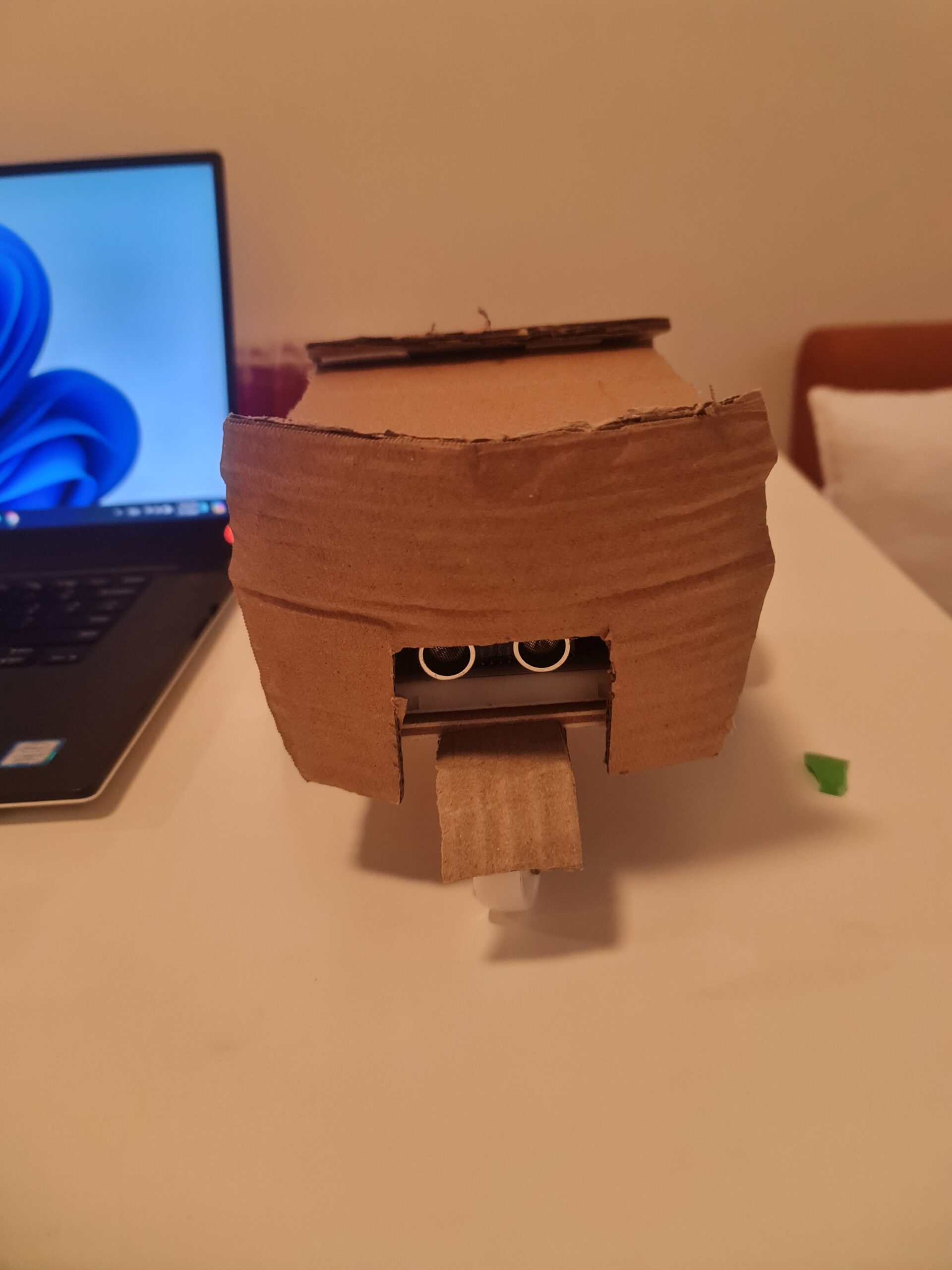
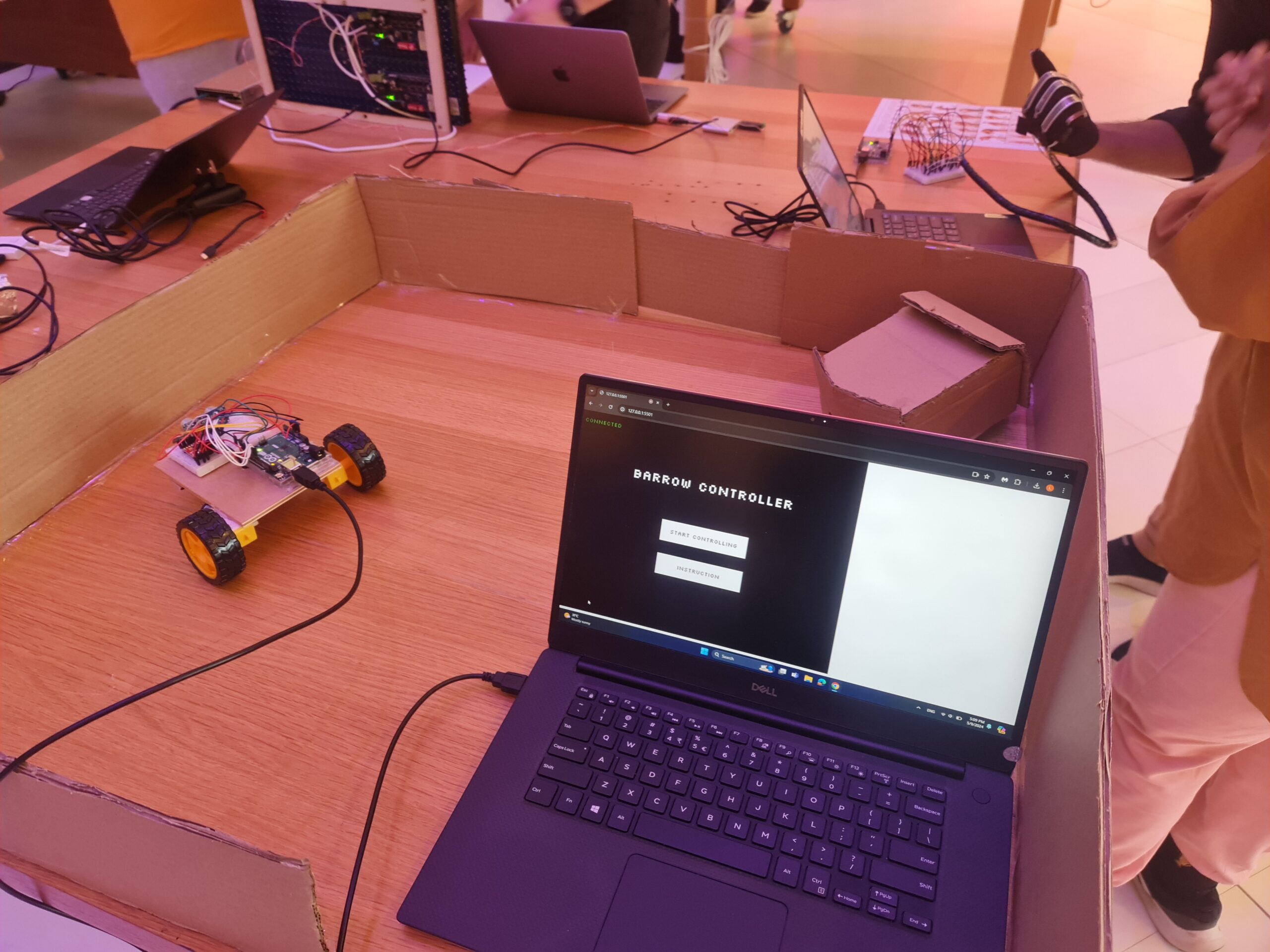
Images of the project
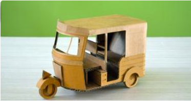
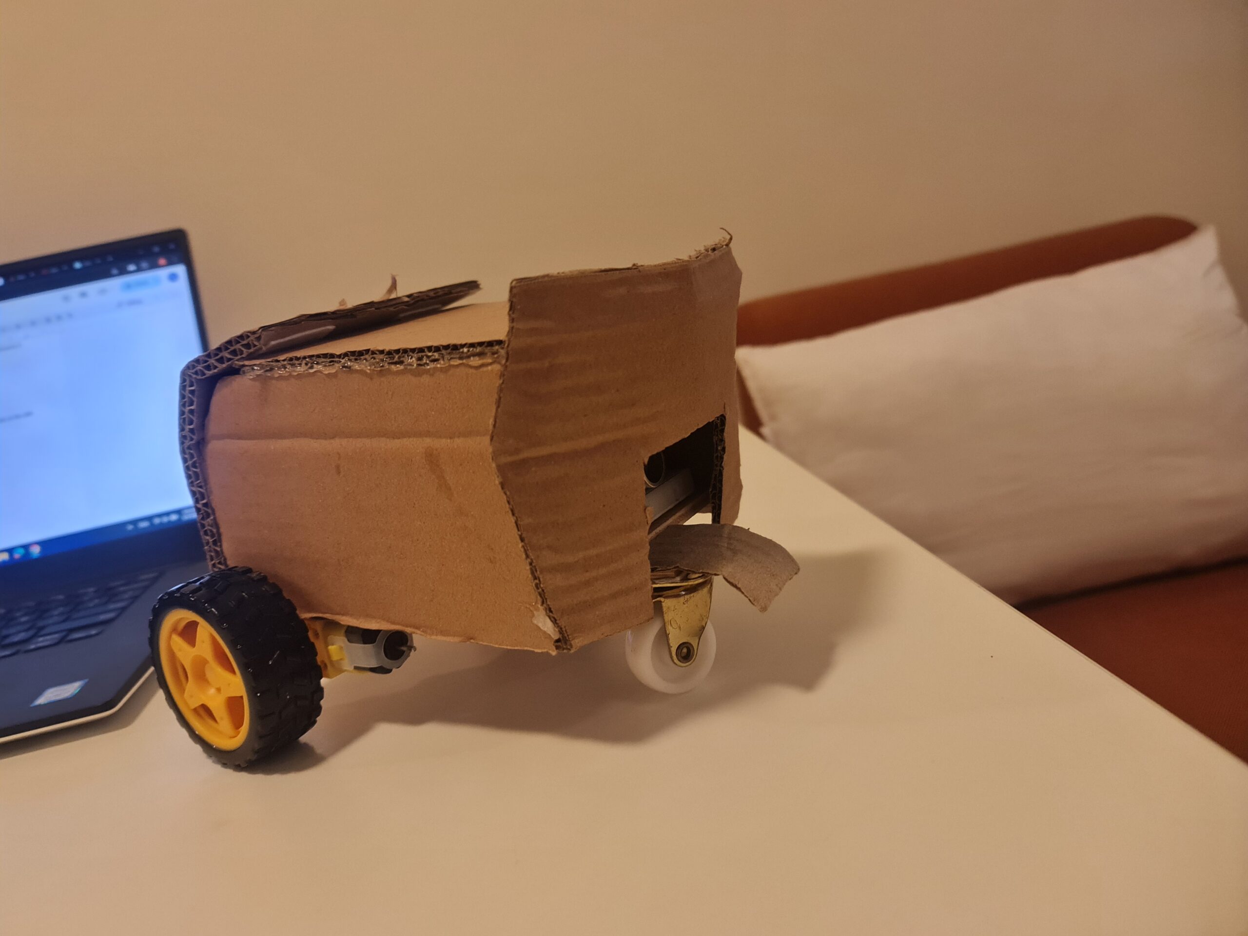
Design inspiration:
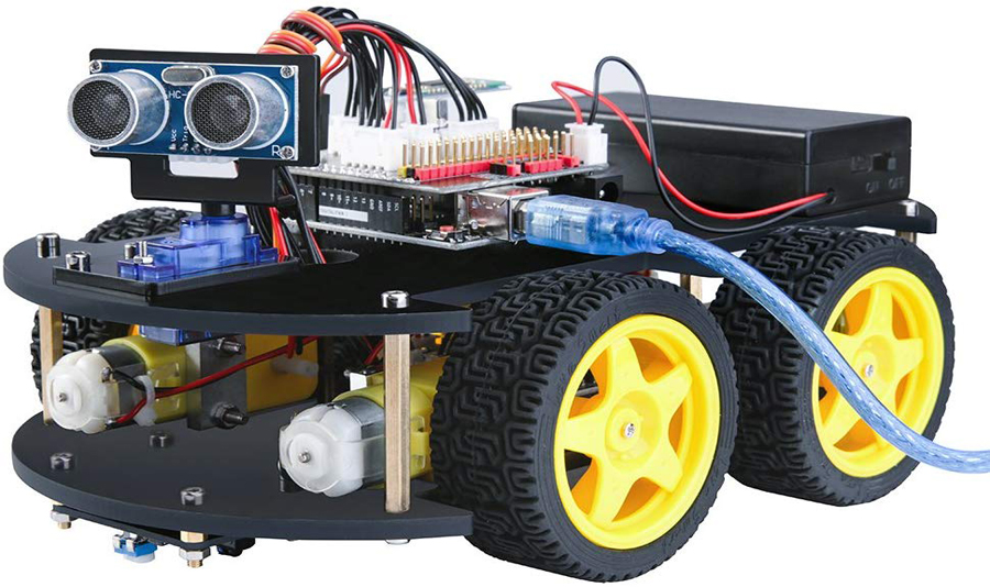
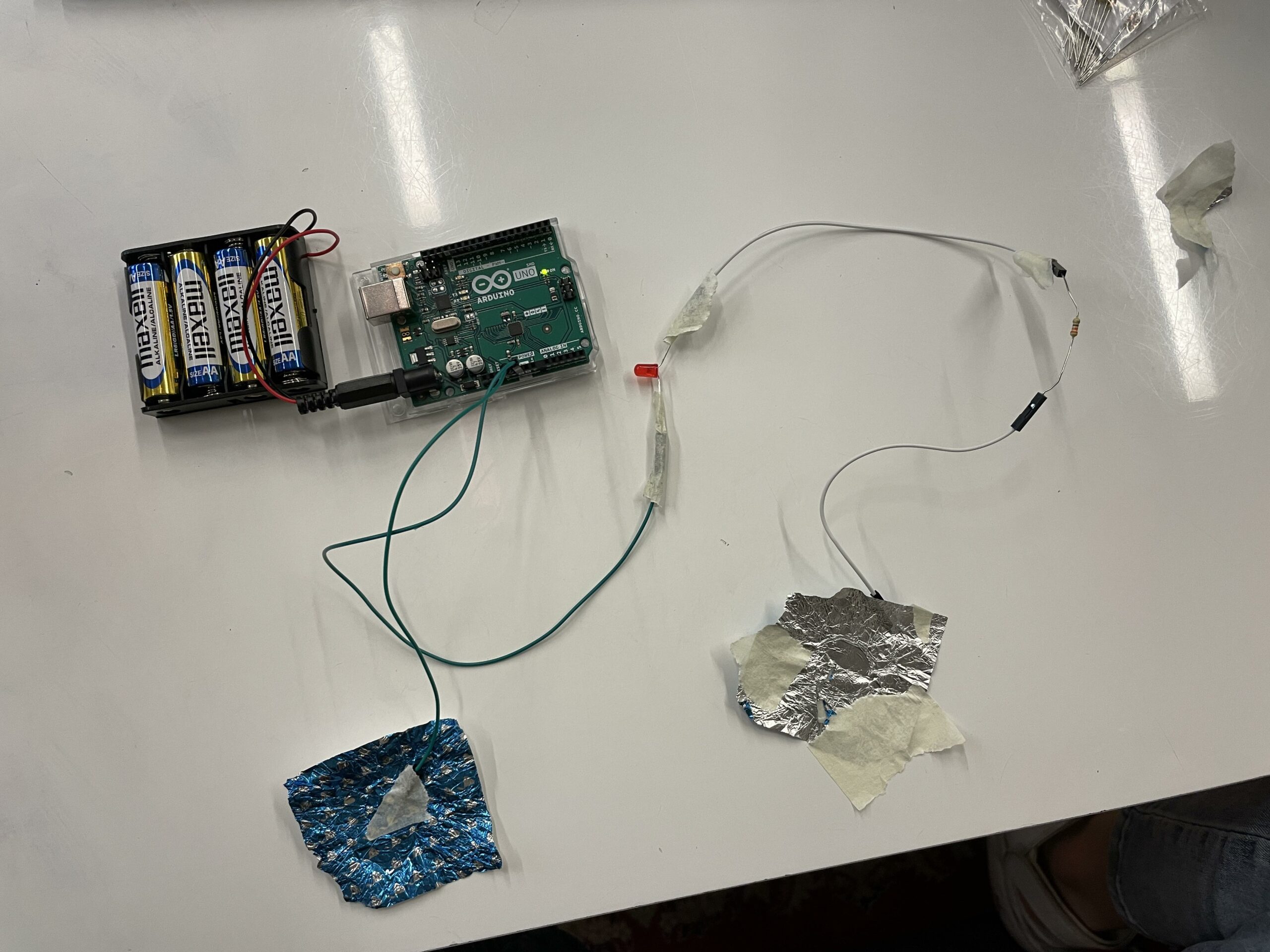
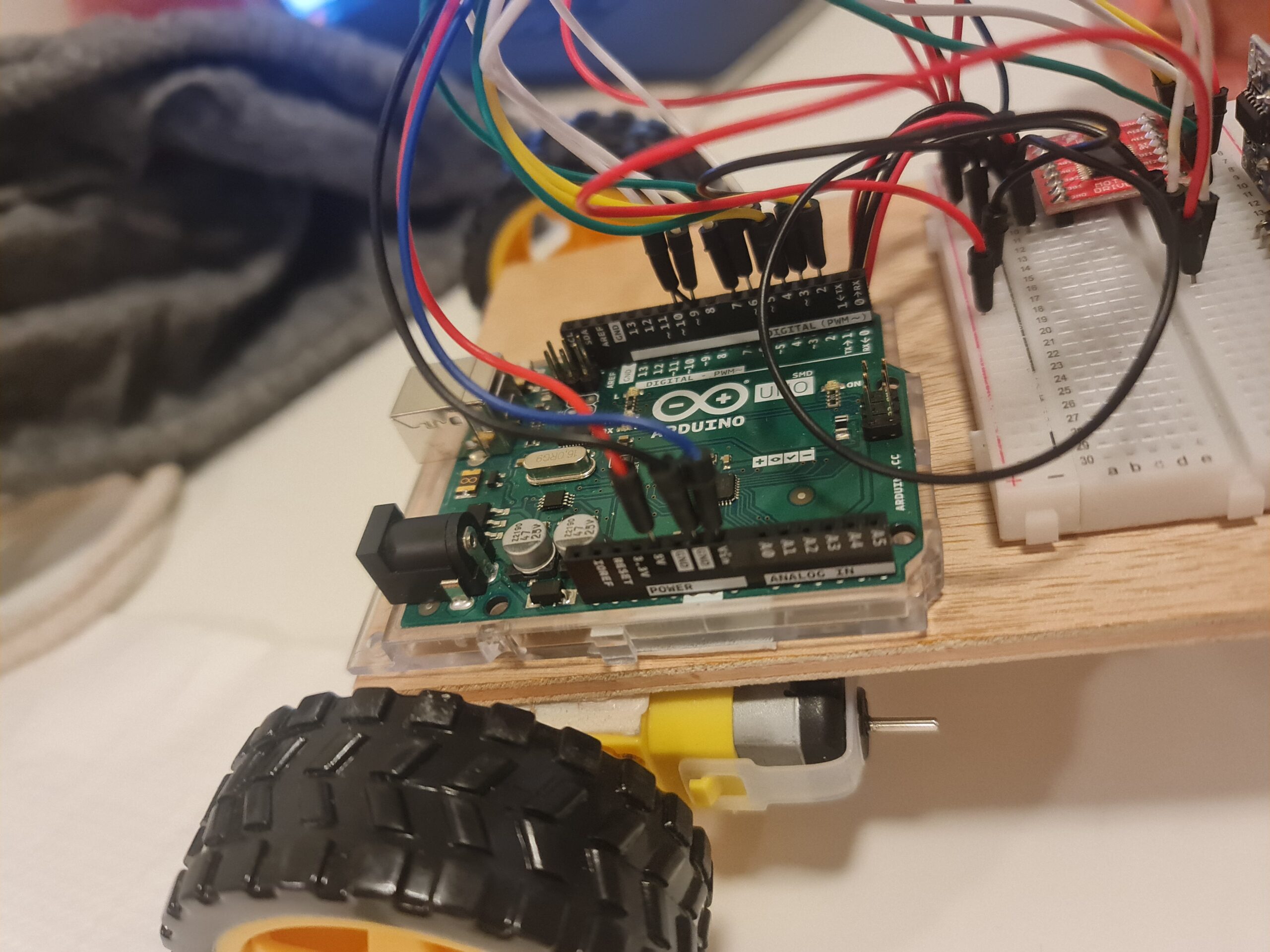
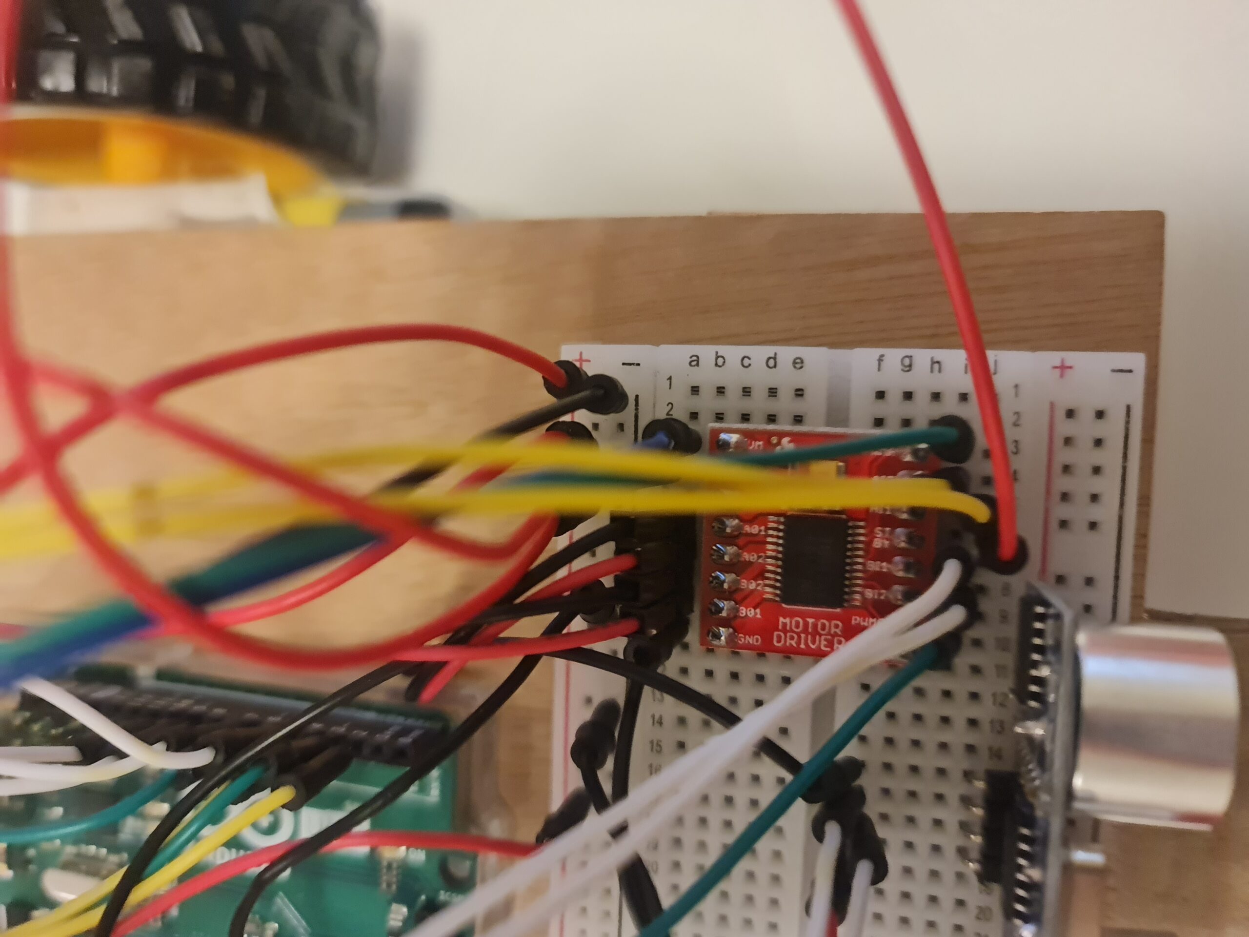
Physical Parts:

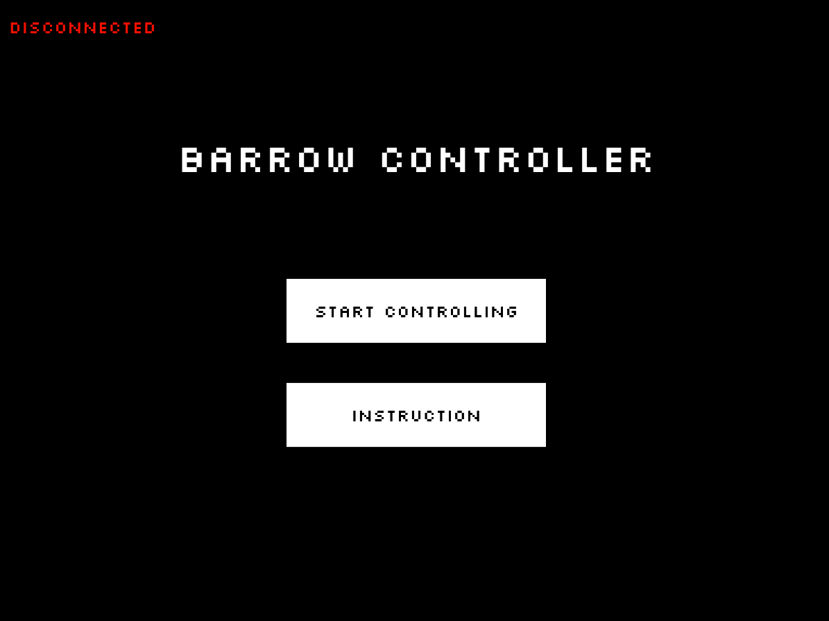
P5.js images:
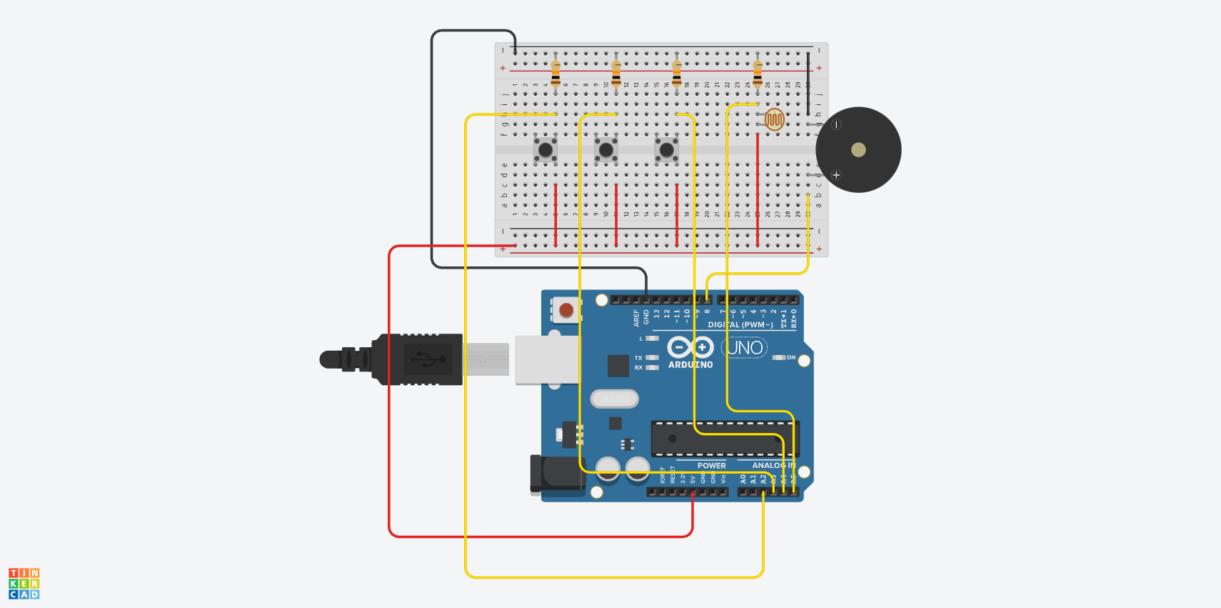
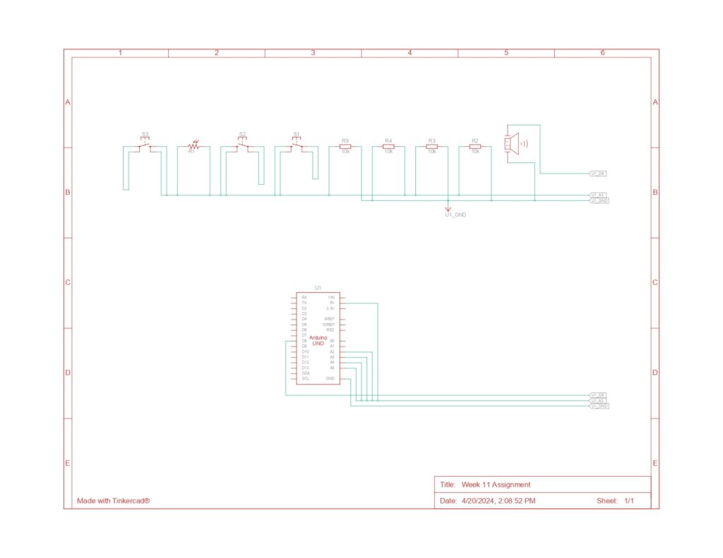
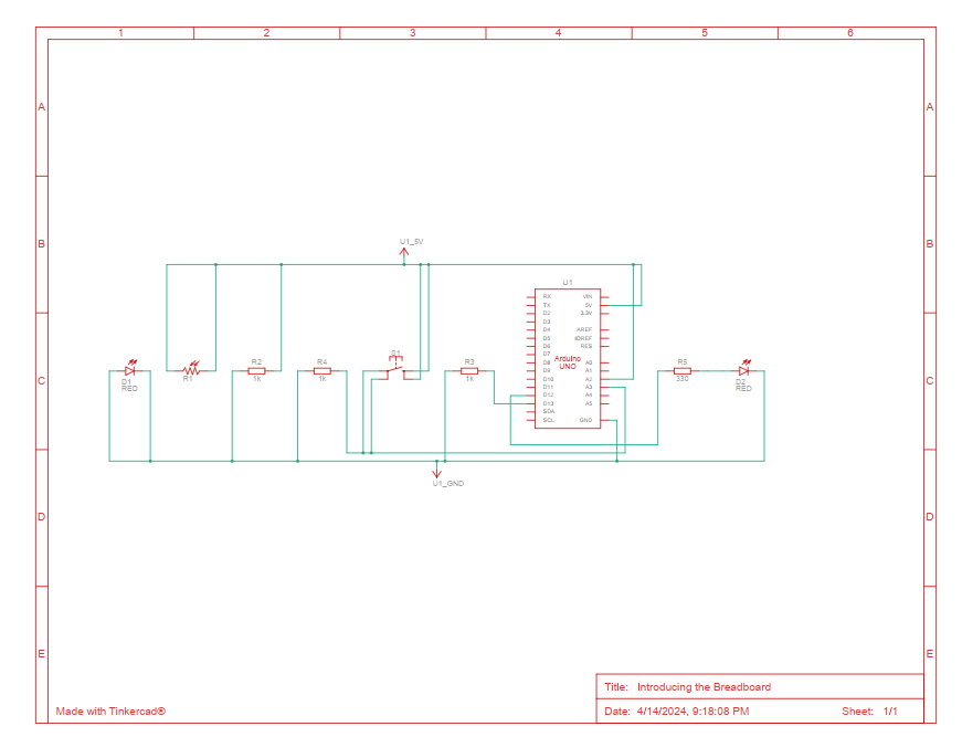
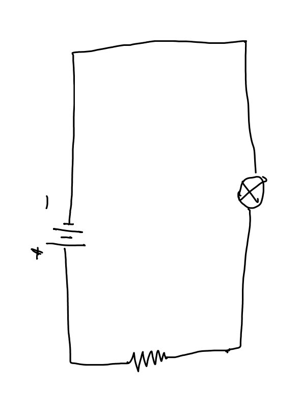
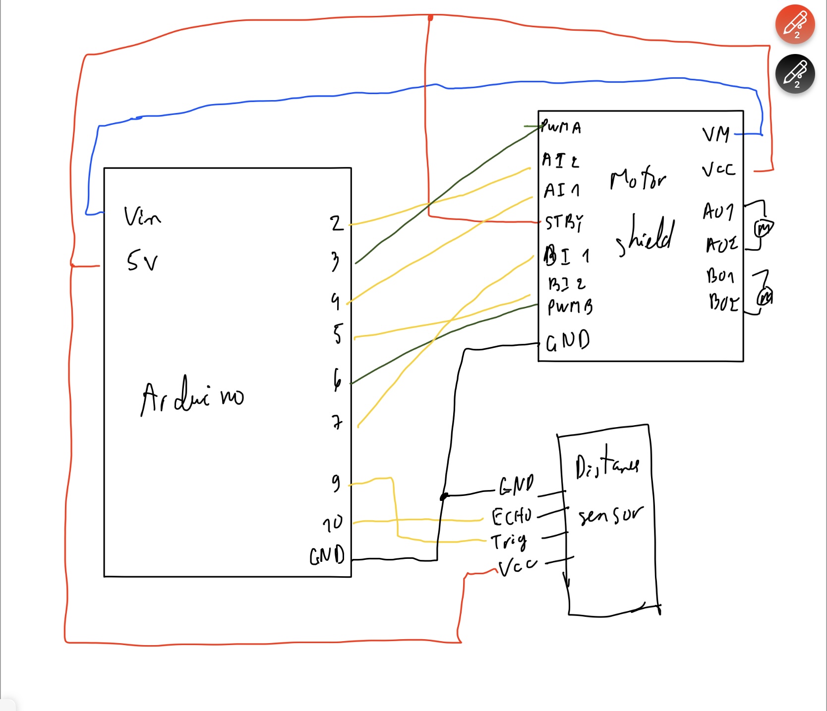
Schematic Diagram
p5.js Embedded
Link to fullscreen
User Testing Videos
Implementation
Interaction Design:
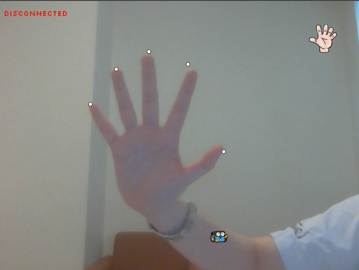
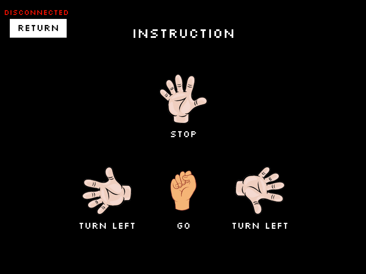
The main components of the project is the handpose model of the ML5.js library. Use its model, the hands are used as a controller for the motor. There are different types of actions that the users can interact with the project. First is the simple hand poses such as showing the palm, fist, turn it to 90 degrees. Each of this will give a different command to the motor which are stop, go, turn left/right respectively.
Since the recognition of the hand joints are done by the handpose library, I just need to give the conditional actions based on the position of the fingers. It is quite difficult to recognize the correct patterns of the of different hand poses initially. There are a lot of trial and errors to identify different hand patterns.
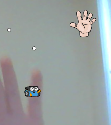
There are a lot of illustration on the screen as the instructions of the project. However, I further made a small icon of the Arduino car as a small companion with the users. This will display the direction in which the user is giving the command by moving in that direction.
Below is a block of code for recognizing the hand poses and giving the corresponding order:
if (indexFinger[1] > thumb[1] && middleFinger[1] > thumb[1] && ringFinger[1] > thumb[1] && pinky[1] > thumb[1]){
  if (middleFinger[0] > thumb[0] + 80){
    // console.log("run");
    // console.log("turn right");
    commandRight = 1;
    commandLeft = 0;
    x++;

    push();
    imageMode(CENTER);
    image(right, 100, 100, 100, 100);
    pop();

  }
  else if (middleFinger[0] < thumb[0] - 80){
    // console.log("stop");
    // console.log("turn left");
    commandRight = 0;
    commandLeft = 1;
    x--;

    push();
    imageMode(CENTER);
    image(left, 100, 100, 100, 100);
    pop();

  }
  else{
    // console.log("straight");
    commandRight = 1;
    commandLeft = 1;
    y--;

    push();
    imageMode(CENTER);
    image(fist, 100, 100, 100, 100);
    pop();

  }
}
else{
  // console.log("stop");
  commandLeft = 0;
  commandRight = 0;
  push();
  imageMode(CENTER);
  image(straight, 100, 100, 100, 100);
  pop();

}
However, you can notice that there is no command for going backward. This is the decision of the motor. Currently, there is no actual machine learing algorithm in the project, the project is just using simple decision making that is giving a portion of decision to the motor. The motor only decides to go back if and only if there is an obstacle blocking its way. This is done using a ultrasonic distance sensor. When the value is smaller than a certain threshold. After it detect an obstacle, the motor will automatically go backward and turn 180 degrees. Below is portion of code for that:
  if (rand) {
    digitalWrite(ain1Pin, HIGH);
    digitalWrite(ain2Pin, LOW);
    analogWrite(pwmAPin, potVal);

    // digitalWrite(bin1Pin, LOW);
    // digitalWrite(bin2Pin, LOW);
    analogWrite(pwmBPin, 0);
  }
  else{
    digitalWrite(bin1Pin, LOW);
    digitalWrite(bin2Pin, HIGH);
    analogWrite(pwmBPin, potVal);

    // digitalWrite(ain1Pin, LOW);
    // digitalWrite(ain2Pin, LOW);
    analogWrite(pwmAPin, 0);

  }

  unsigned long currentMillis = millis();

  if (currentMillis - previousMillis >= interval) {
    // save the last time you blinked the LED
    previousMillis = currentMillis;
    back = false;
  }
}
Furthermore, to give it some human actions, if it is in contact with one of the obstacles, it will express itself by saying that it don’t want to do that. However, since the showcase situation may be too noisy, the sound will be played in the p5.js side using the computer’s speaker.
P5.js and Arduino Communication:
The hand pose are detected in the p5.js side. Since I have 2 different wheels, I have 2 different variables for the left and the right wheels, the communication of the p5.js to the Arduino sketch is the status of the left and right control variables. The Arduino is then use those information to run the corresponding action.
Below is the Arduino code for processing the p5.js information (p5.js code for this has already be included in the earlier section):
if (!back){
  if (left) { //counterclockwise
    digitalWrite(ain1Pin, LOW);
    digitalWrite(ain2Pin, HIGH);
    analogWrite(pwmAPin, potVal);
  }
  else { //clockwise
    // digitalWrite(ain1Pin, LOW);
    // digitalWrite(ain2Pin, LOW);
    analogWrite(pwmAPin, 0);
  }

  if (right) { //counterclockwise
    digitalWrite(bin1Pin, HIGH);
    digitalWrite(bin2Pin, LOW);
    analogWrite(pwmBPin, potVal);
  }
  else { //clockwise
    // digitalWrite(bin1Pin, LOW);
    // digitalWrite(bin2Pin, LOW);
    analogWrite(pwmBPin, 0);
    // analogWrite(pwmBPin, 255 - potVal / 4);
  }
} else{
  if (cm < 10){
    Serial.print(back);
    Serial.print(',');

    digitalWrite(ain1Pin, HIGH);
    digitalWrite(ain2Pin, LOW);
    analogWrite(pwmAPin, potVal);

    digitalWrite(bin1Pin, LOW);
    digitalWrite(bin2Pin, HIGH);
    analogWrite(pwmBPin, potVal);
  }
For the communication from Arduino back to p5.js, since the small illustration on the screen need to also display the status of going backward, this information in sent to p5.js to know when the motor is going backward to display accordingly. Below is the block of code for that:
if (fromArduino[0] == "1"){
  y++;
  if(prev1 == "0"){
    sound1.play();

  }
}
What I am proud of:
I am really like the way the motor can run by itself without the commands. It is similar to use the state of the surrounding and make the decision by themselves. Even though this is not a machine learning project so it can not think by themselves, a very bare bone of intelligence can be simply made by Arduino.
Also, the implementation of ml5 library is also something new to me. It took me quite a bit of time to figuring out the correct number for the difference threshold of the hand poses. It still does not work that smoothly due to the errors in hand detections.
Resources used:
Challenges:
It was quite difficult to make sure that while the motor is taking the control, the user can no longer control the which direction it can move. Initially, I thought I should done it in the p5.js side where if the variable “back” is true, it can stop sending the information to the Arduino. However, this just stop the whole communication between the p5.js and Arduino. Therefore, I made it to be controlled in the Arduino side. So the variable called “back” is used to control the state and it can only be reset after the motor finish doing its role.
Apart from this is that I need to implement the decision of turn itself 180 degrees right after running backward for a while. Since I cannot use delay which will cause the motor to stop running, I used Blink without Delay technique to set the status and duration of the turning. Below is an illustration of this logic:
unsigned long currentMillis = millis();

if (currentMillis - previousMillis >= interval) {
  // save the last time you blinked the LED
  previousMillis = currentMillis;
  back = false;
}
Improvements:
One of the things that I want to do is that the illustration on the screen can be mapped to the actual distance travelled by the motor. However, since the power of the motor is not the same as speed, I was not able to implement this.
Also, I would like to allow the motor to have more decision making and not just return and simple speech. I think this also require complex analysis of the roles between the human and the machine.
IM Showcase:
The showcase went smoothly general. However, there are minor problems with the motor running. For example, the wire is stuck which is preventing the motor to run. One of the motor for some reason is significantly weaker than the other, so the device does not go in a straight line. Also, because of the lighting in the room, the ML5 library failed to detect the hand poses multiple times. I recognize that the environment plays a big role in keeping the project running smoothly.
Image:
Below are the videos of the user interaction during the show: