Introduction
Transitioning from the conceptualization of ArtfulMotion, a project centered around translating gestures into visual art, I sought to elevate the interactive experience by integrating physical computing. This blog post outlines the genesis of the gesture-controlled robot concept, the nuanced implementation, and the resultant user experiences.
Inspiration and Conceptualization
The inception of this project emanated from a desire to imbue physicality into the realm of gesture-controlled art, a departure from the digital interface. Initially considering an “electronic buddy” or an “art robot,” inspiration struck upon encountering a multidirectional moving robot in a video shared by Professor Riad. The challenge was to replicate this unique motion with standard tires and integrate Bluetooth technology, ultimately opting for a tethered connection.
Gesture Recognition
Leveraging the handpose model from ml5.js, the implementation of gesture recognition unfolded by identifying 21 keypoints on a hand. The model, confined to recognizing one hand at a time, prompted the division of the video feed into segments, each corresponding to a distinct direction of motion. The chosen gestures prioritize intuitive and natural user interactions.
Interaction Design
User interaction revolves around using hand movements captured by a webcam, transforming them into navigational commands for the robot. An onboard button toggles the robot’s state, turning it on or off. Although the current iteration lacks auditory feedback, prospective enhancements will explore the integration of sound cues. The unique motion of the robot necessitates users to rely on intuition, adding an element of engagement.
Technical Implementation
The interaction between the p5.js sketch and the Arduino board relies on tethered serial communication, facilitated by the p5.web-serial.js library. A singular value is dispatched from p5 to Arduino, intricately mapped to specific motion sets.
p5.js sketch:
preload():
function preload() {

  instructionPage = loadImage('instructions.png');

  for (let i = 1; i <= carNum; i++) {
    carArray.push(new Sprite(spriteWidth, spriteHeight, 160, 80));
    carArray[i - 1].x = 80 + i * 20;
    carArray[i - 1].y = 100 * i;
    carArray[i - 1].spriteSheet = 'spritesheet.png';
    carArray[i - 1].anis.offset.x = 5;
    carArray[i - 1].anis.frameDelay = 8;

    carArray[i - 1].addAnis({
      move: { row: 0, frames: 16 },
    });
    carArray[i - 1].changeAni('move');
    carArray[i - 1].layer = 2;
    carArray[i - 1].visible = false;
  }
}
The preload() function loads the instruction page image and initializes an array of car sprites.
setup():
function setup() {
  createCanvas(windowWidth, windowHeight);
  video = createCapture(VIDEO);
  video.size(width, height);

  handpose = ml5.handpose(video, modelReady);
  handpose.on("predict", results => {
    predictions = results;
  });

  video.hide();
}
The setup() function serves as the initial configuration for the canvas, video capture, and the Handpose model. It establishes the canvas size based on the current window dimensions and initializes the necessary components, such as the video capture object and Handpose model. The modelReady callback function is triggered when the Handpose model is prepared for use, ensuring that the application is ready to detect hand poses accurately.
draw():
function draw() {
  background(255);

  flippedVideo = ml5.flipImage(video);

  // Calculate the aspect ratios for video and canvas
  videoAspectRatio = video.width / video.height;
  canvasAspectRatio = width / height;


  // Adjust video dimensions based on aspect ratios
  if (canvasAspectRatio > videoAspectRatio) {
    videoWidth = width;
    videoHeight = width / videoAspectRatio;
  } else {
    videoWidth = height * videoAspectRatio;
    videoHeight = height;
  }

  // Calculate video position
  video_x = (width - videoWidth) / 2;
  video_y = (height - videoHeight) / 2;

  if (currentPage == 1) {
    // display instructions page
    image(instructionPage, 0, 0, width, height);
  }
  else if (currentPage == 2) {
    // serial connection page
    if (!serialActive) {
      runSerialPage();
    }

    else {
      // hides car animation
      for (let i = 0; i < carNum; i++) {
        carArray[i].visible = false;
      }

      // controlling page
      if (controlState) {
        runControllingPage();
      }

      // device has been turned off
      else {
        runTorqueyOff();
      }
    }
  }
}
Within the draw() function, various elements contribute to the overall functionality of the sketch. The calculation of video and canvas aspect ratios ensures that the video feed maintains its proportions when displayed on the canvas. This responsiveness allows the application to adapt seamlessly to different window sizes, providing a consistent and visually appealing user interface.
The draw() function is also responsible for managing different pages within the application. It evaluates the currentPage variable, determining whether to display the instruction page or proceed to pages related to serial connection and hand gesture control. This page-switching behavior is facilitated by the mousePressed function, enabling users to navigate through the application intuitively.
readSerial(data):
function readSerial(data) {

  if (data != null) {
    ////////////////////////////////////
    //READ FROM ARDUINO HERE
    ////////////////////////////////////
    if (int(trim(data)) == maxVoltReading) {
      controlState = true;
    }
    else if (int(trim(data)) == minVoltReading){
      controlState = false;
    }

    //////////////////////////////////
    //SEND TO ARDUINO HERE (handshake)
    //////////////////////////////////

    let sendToArduino = value + "\n";
    writeSerial(sendToArduino);

    // reset value
    value = defaultState;
  }
}
The readSerial(data) function handles communication with an Arduino device. It interprets incoming data, updates the controlState based on voltage readings, and initiates a handshake with the Arduino. This interaction establishes a connection between the physical device and the digital application, enabling real-time responses to user inputs.
drawKeypoints():
function drawKeypoints() {
  for (let i = 0; i < predictions.length; i += 1) {
    const prediction = predictions[i];
    let area = [0, 0, 0, 0, 0];
    for (let j = 0; j < prediction.landmarks.length; j += 1) {
      const keypoint = prediction.landmarks[j];
      fill(0, 255, 0);
      noStroke();
      let x = map(keypoint[0], 0, 640, 0, videoWidth);
      let y = map(keypoint[1], 0, 480, 0, videoHeight);
      ellipse(x, y, 10, 10);

      // count number of trues
      // -- helps to detect the area the detected hand is in
      if (withinLeft(x, y)) {
        area[0] += 1;
      }
      if (withinTopCenter(x, y)) {
        area[1] += 1;
      }
      if (withinRight(x, y)) {
        area[2] += 1;
      }
      if (withinMiddleCenter(x, y)) {
        area[3] += 1;
      }
      if (withinBottomCenter(x, y)) {
        area[4] += 1;
      }
      // end of count
    }

    // print index
    for (let i = 0; i < area.length; i += 1) {
      if (area[i] == 21) {
        value = i;
      }
    }
  }
}
The drawKeypoints() function utilizes the Handpose model’s predictions to visualize detected keypoints on the canvas. These keypoints correspond to various landmarks on the hand, and their positions are mapped from the video coordinates to the canvas coordinates. By counting the number of keypoints within specific regions, the function determines the area of the hand’s position. This information is crucial for the application to interpret user gestures and trigger relevant actions.
Robot Movement
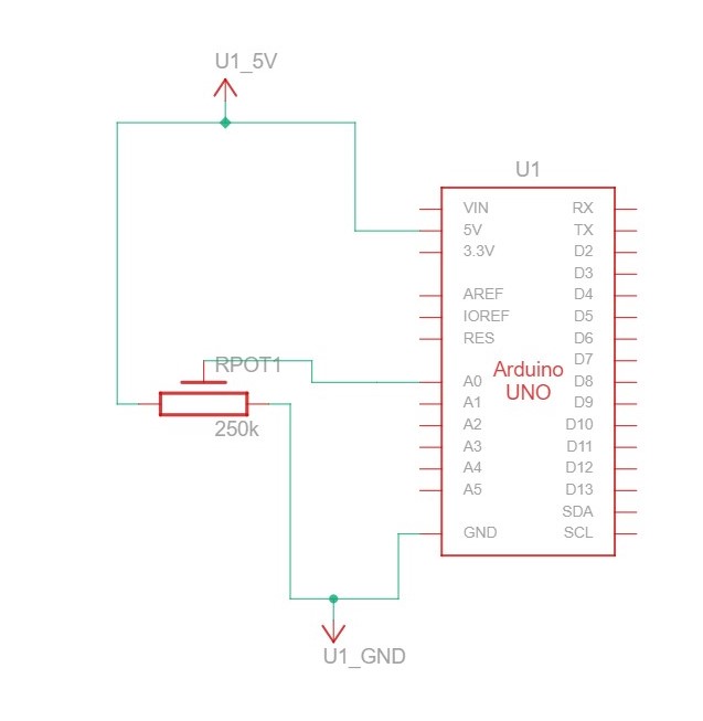
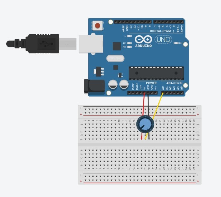
Arduino schematic diagram:
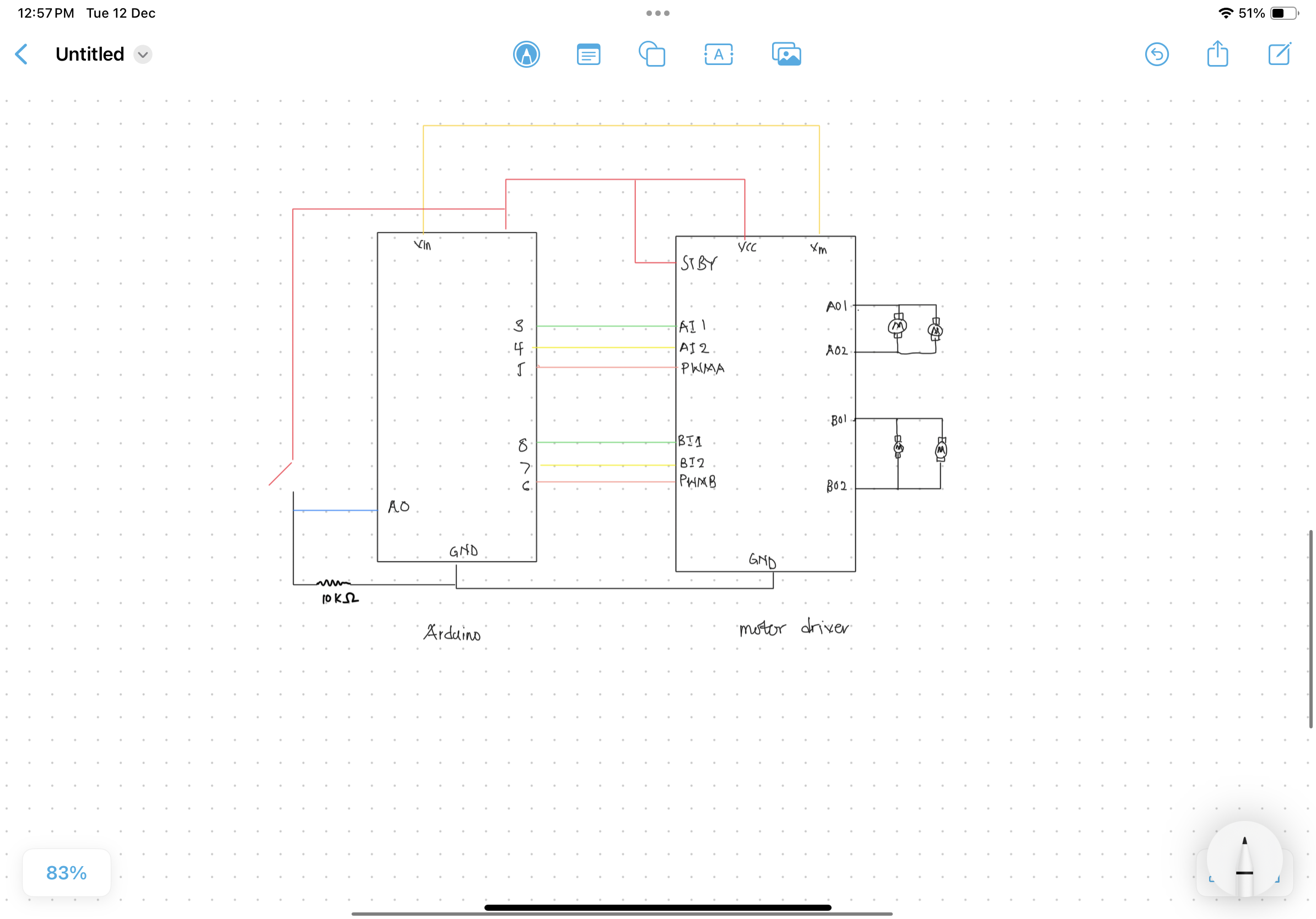
The robot’s movement encompasses pseudo-forward, pseudo-backward, and rotational movements in either direction around its center. Achieving these nuanced movements involved a methodical trial-and-error process, aligning gestures with intended actions.
Arduino sketch
const int ain1Pin = 3;
const int ain2Pin = 4;
const int pwmAPin = 5;

const int bin1Pin = 8;
const int bin2Pin = 7;
const int pwmBPin = 6;

int buttonValue = 0;
int prevButtonValue = 0;
const int defaultState = -1;

const unsigned long eventInterval = 1000;
unsigned long previousTime = 0;

void setup() {
  // Start serial communication so we can send data
  // over the USB connection to our p5js sketch
  Serial.begin(9600);

  pinMode(LED_BUILTIN, OUTPUT);

  pinMode(ain1Pin, OUTPUT);
  pinMode(ain2Pin, OUTPUT);
  pinMode(pwmAPin, OUTPUT); // not needed really

  pinMode(bin1Pin, OUTPUT);
  pinMode(bin2Pin, OUTPUT);
  pinMode(pwmBPin, OUTPUT); // not needed really

  // TEST BEGIN
  // turn in one direction, full speed
  analogWrite(pwmAPin, 255);
  analogWrite(pwmBPin, 255);
  digitalWrite(ain1Pin, HIGH);
  digitalWrite(ain2Pin, LOW);
  digitalWrite(bin1Pin, HIGH);
  digitalWrite(bin2Pin, LOW);

  // stay here for a second
  delay(1000);

  // slow down
  int speed = 255;
  while (speed--) {
    analogWrite(pwmAPin, speed);
    analogWrite(pwmBPin, speed);
    delay(20);
  }

  // TEST END

  buttonValue = analogRead(A0);
  prevButtonValue = buttonValue;

  // start the handshake
  while (Serial.available() <= 0) {
    digitalWrite(LED_BUILTIN, HIGH); // on/blink while waiting for serial data
    Serial.println(buttonValue); // send a starting message
    delay(50);            // wait 1/3 second
    digitalWrite(LED_BUILTIN, LOW);
    delay(50);
  }

}

void loop() {

   /* Updates frequently */
  unsigned long currentTime = millis();
  /* This is the event */
  if (currentTime - previousTime >= eventInterval) {
    /* Event code */
    buttonValue = analogRead(A0);

   /* Update the timing for the next time around */
    previousTime = currentTime;
  }

  while (Serial.available()) {
    // sends state data to p5
    if (buttonValue != prevButtonValue) {
      prevButtonValue = buttonValue;
      Serial.println(buttonValue);
    }
    else {
      Serial.println(defaultState);
    }

    // led on while receiving data
    digitalWrite(LED_BUILTIN, HIGH);

    // gets value from p5
    int value = Serial.parseInt();

    // changes brightness of the led
    if (Serial.read() == '\n' && buttonValue == 1023) {

      if (value == 0) {
        // 0
        digitalWrite(ain1Pin, HIGH);
        digitalWrite(ain2Pin, LOW);
        digitalWrite(bin1Pin, LOW);
        digitalWrite(bin2Pin, HIGH);

        analogWrite(pwmAPin, 255);
        analogWrite(pwmBPin, 255);
        // 0

      }

      else if (value == 1) {
        // 1
        digitalWrite(ain1Pin, HIGH);
        digitalWrite(ain2Pin, LOW);
        digitalWrite(bin1Pin, HIGH);
        digitalWrite(bin2Pin, LOW);

        analogWrite(pwmAPin, 255);
        analogWrite(pwmBPin, 255);
        // 1
      }

      else if (value == 2){
        // 2
        digitalWrite(ain1Pin, LOW);
        digitalWrite(ain2Pin, HIGH);
        digitalWrite(bin1Pin, HIGH);
        digitalWrite(bin2Pin, LOW);

        analogWrite(pwmAPin, 255);
        analogWrite(pwmBPin, 255);
        // 2
      }

      else if (value == 3) {
        analogWrite(pwmAPin, 0);
        analogWrite(pwmBPin, 0);
      }

      else if (value == 4) {
        // 4
        digitalWrite(ain1Pin, LOW);
        digitalWrite(ain2Pin, HIGH);
        digitalWrite(bin1Pin, LOW);
        digitalWrite(bin2Pin, HIGH);

        analogWrite(pwmAPin, 255);
        analogWrite(pwmBPin, 255);
        // 4
      }

      else {
        analogWrite(pwmAPin, 0);
        analogWrite(pwmBPin, 0);
      }
    }
  }
  // led off at end of reading
  digitalWrite(LED_BUILTIN, LOW);
}
The setup() function initializes serial communication, configures pins, and performs an initial motor test. Additionally, it sends the initial buttonValue to the p5.js sketch for the handshake.
The loop() function checks if the eventInterval has elapsed and updates the buttonValue accordingly. It handles incoming serial data from the p5.js sketch, sending state data back and adjusting LED brightness. Motor control logic is implemented based on the received values from the p5.js sketch, allowing for different motor configurations.
User Experience
End users find the robot’s unconventional design intriguing, coupled with a sense of awe at its mobility. The brief learning curve is accompanied by occasional glitches arising from imperfections in handpose detection, which may result in initial user frustration.
User Testing
IM Showcase
The IM showcase went well overall. Despite a few technical hiccups during the presentation, the feedback from people who interacted with the project was positive. Some issues raised were ones I had anticipated from user testing, and I plan to address them in future versions of the project.
User Interaction 1:
User Interaction 2:
Aesthetics and Design
Crafted predominantly from cardboard, the robot’s casing prioritized rapid prototyping, considering time constraints. The material’s versatility expedited the prototyping process, and the strategic use of zipties and glue ensured durability, with easily replaceable parts mitigating potential damage.
Future Enhancements
Subsequent iterations of ArtfulMotion 2.0 aspire to introduce gesture controls for variable speed, operational modes such as tracking, and exploration of more robust machine learning models beyond the limitations of handpose. The quest for wireless control takes precedence, offering heightened operational flexibility, potentially accompanied by a structural redesign.
Reflection
The completion of this project within constrained timelines marks a journey characterized by swift prototyping, iterative testing, and redesign. Future endeavors shift focus towards refining wireless communication, structural enhancements, and the exploration of advanced machine learning models.
p5 rough sketch:
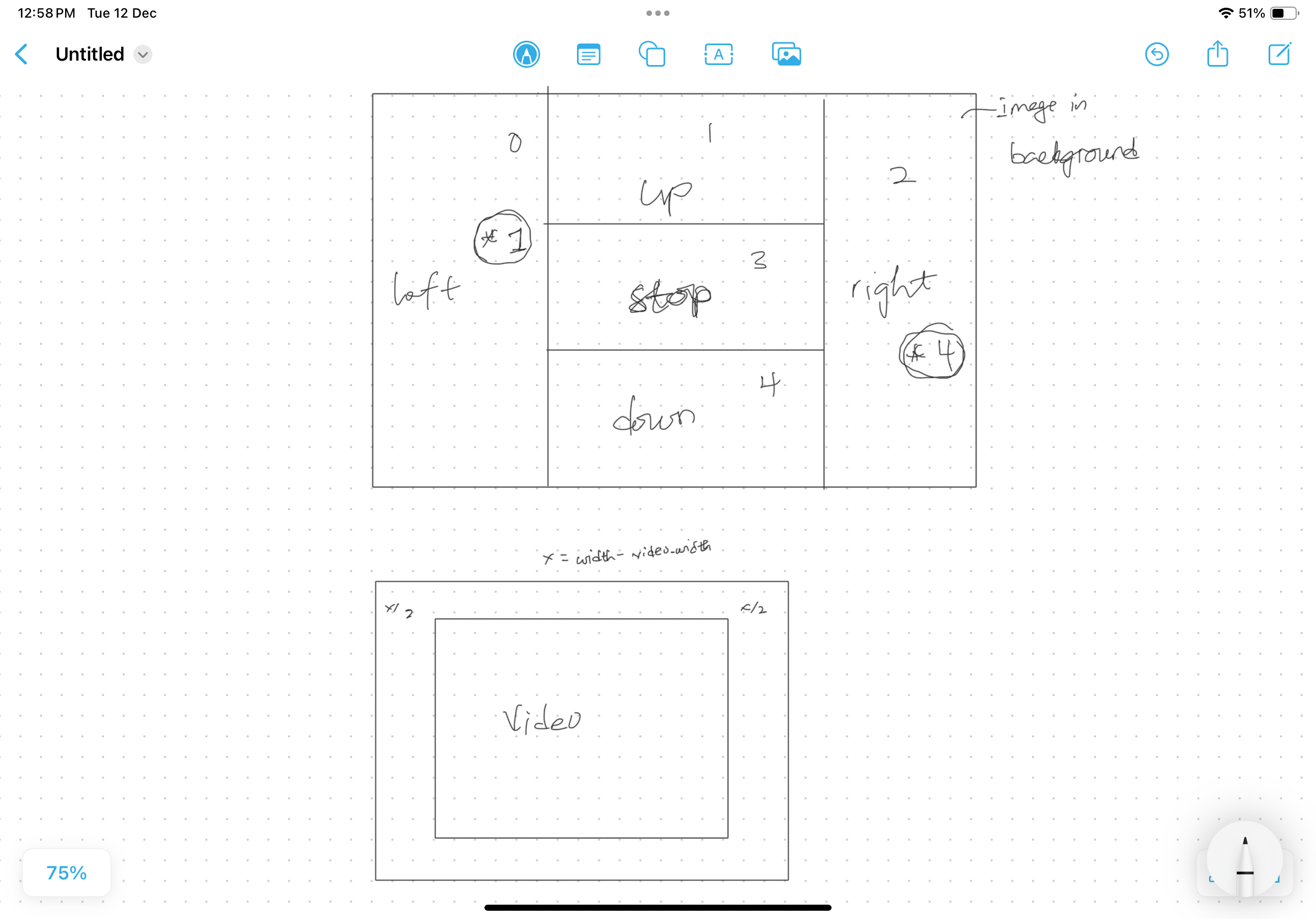
P5 Sketch