Final project: user testing

User testing video:

I gave a user a try of the project after I finished the pairing and connection, and he was able to figure out what everything meant. He was very smart and was able to figure out what should be done even with my hints being somewhat not quite directional. Also, my intention for this project is to let the user figure out what everything does because one thing about cats is that it is hard to get what they mean, and finding out what everything is is part of the process. Eventually, my tester understood everything and had fun playing around with it.

During the testing, basically, everything turned out well. The only thing that might be improved is that sometimes when you are obviously mean towards the cat, she becomes more affectionate and happier, which should not be happening. That is also why I added to the notes that the cat’s change in emotions can be quite unpredictable. It is the problem with the AI model, so I don’t have a fix for it. Another thing is that the API only accepts three inputs per minute. therefore if the user input too fast the program might crash because the parseInt function can get nothing and the mood becomes corrupted. I couldn’t think of a way that could fix this.

For now, I think I don’t need to explain anything more because the exploration is part of the process. but I might find the need to do further explaining when giving this to a wider audience. I could add a page to the “help” button to explain the whole mechanism but I truly believe that would decrease the fun and make it really a simulator instead of an experience.

Final Project: CyberCat

Concept:

I chose this prompt because I have always wanted a pet but my parents won’t let me have one. Therefore I am doing this prompt as sort of a make up for the thing that I always wanted but never got.

The whole concept is easy. The user as the owner of the pet, interacts with the pet by “talking” to it (typing in messages to “say” to the cat”). After the cat “hears” what the human says, it will evaluate whether the human is being mean or not. This evaluation is achieved through the GPT-3.5-Turbo API. If the cat thinks the human is being mean, it will become less happy, which is represented by decreasing her mood on a scale of 1 to 10, and vice versa. There are two main functions the user can do with the pet for now. One is to talk with it and observe its actions, and the other is an attempt to pet it. If the human chooses to talk with it, a buzzer on the physical CyberCat will start beeping as if responding. The happier the cat is, the slower and calmer the cat’s sound will be. However, if she is very pissed, her sound will be high-speed and rapid. On the other hand, when you try to pet her, it will choose based on its mood. If she is happy (mood 5 or above), she will come towards you until she senses you within 20 centimeters. But if she is not happy, she will back away from you until you are separated for at least 50 seconds.

I also put an “easter egg” in the project, that is if you type in “dance” in the message box, it will give you this sort of “dance” as if trying to catch her own tail.

Video Introduction to Interaction:

Implementation:

The Interaction design is very simple.  For the talk function, it is a simple one way transmission. The user inputs through keyboard, and the p5 script processes the input and send message to the Arduino, which responds to the message by making the buzzer beep. For the other, there is a sort of data processing added on top of the other function. after command is given to the Arduino, it will check a condition first, and then act in response to the condition.

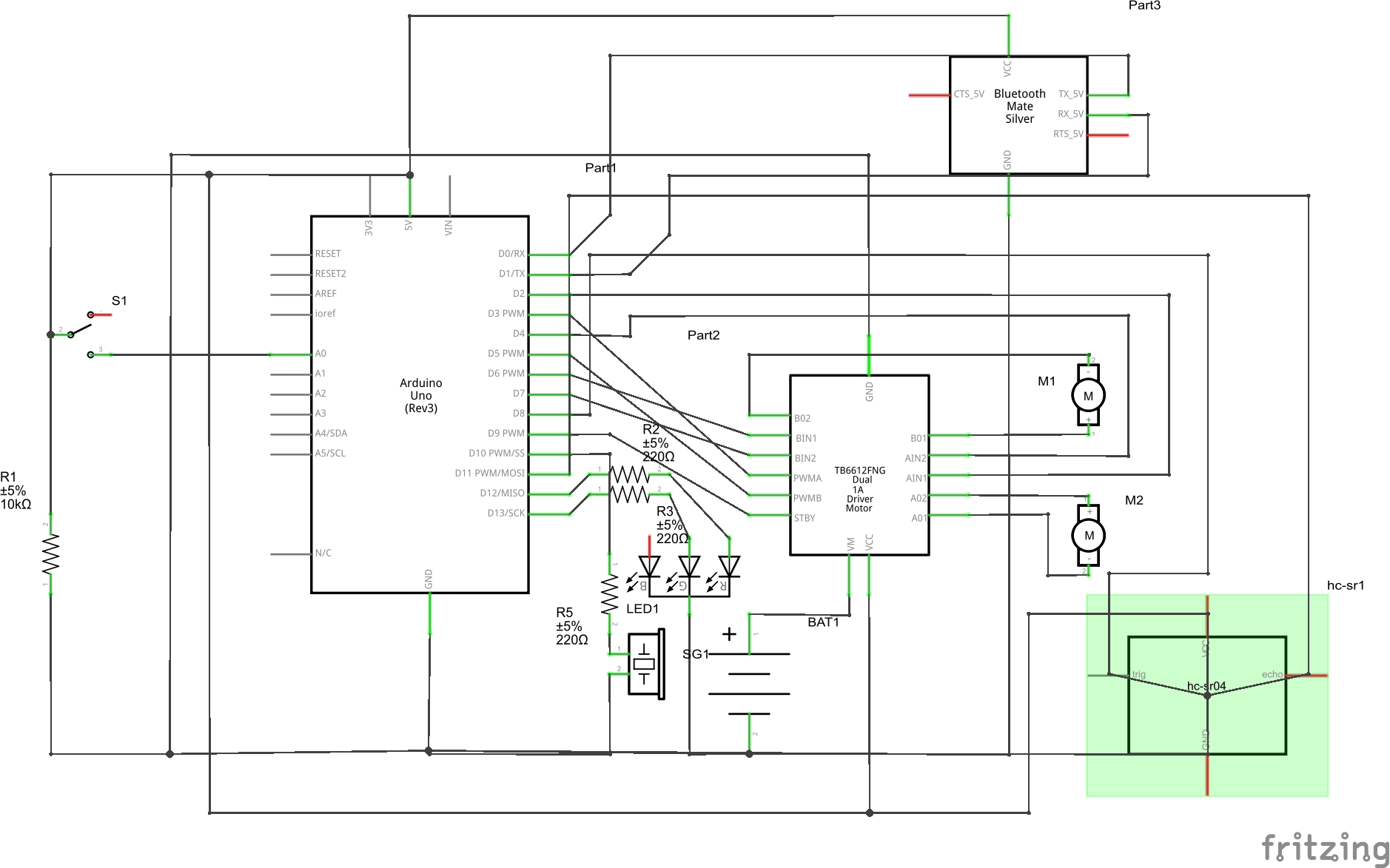
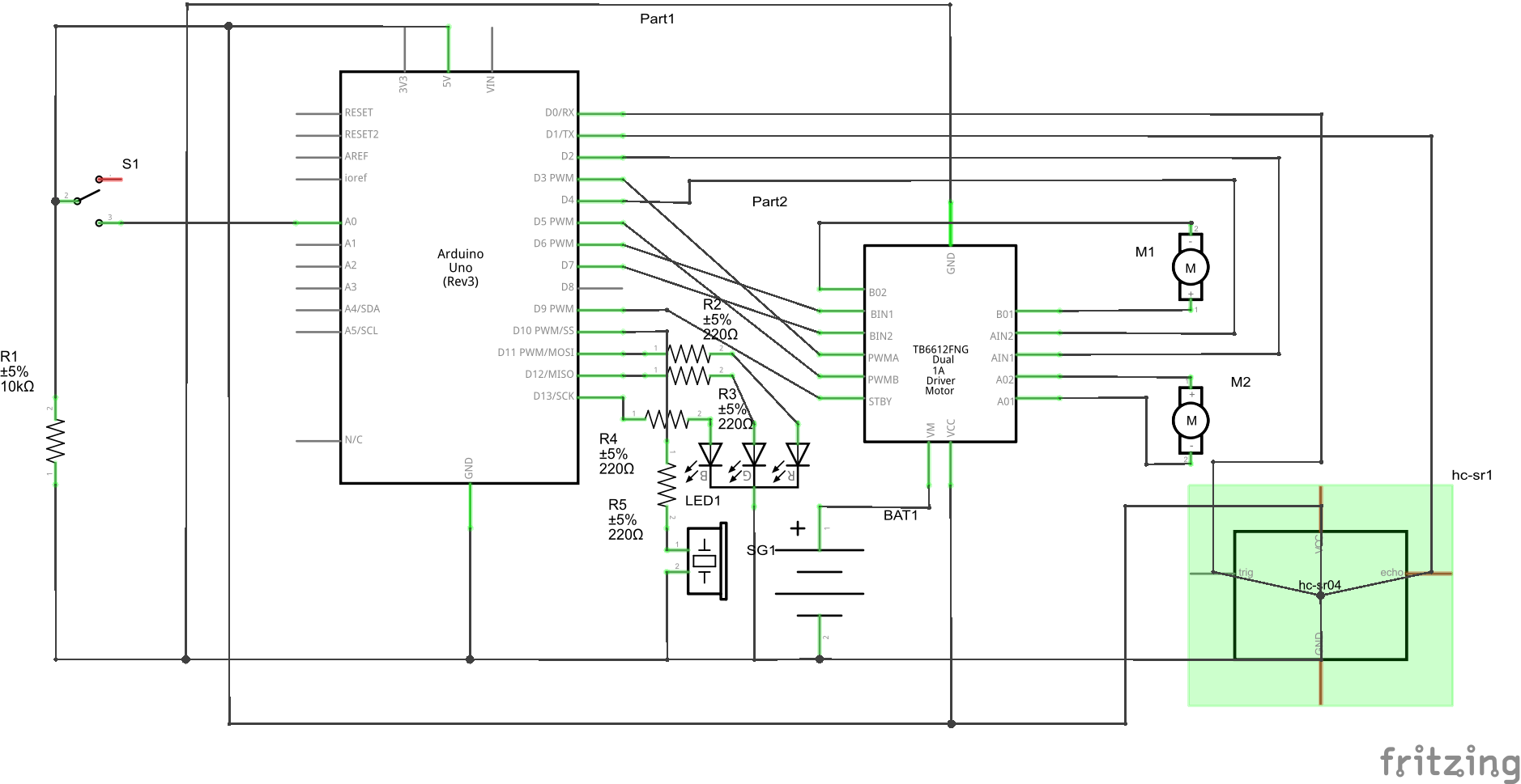
This is the schematic of the project. The pins do not necessarily correspond to the ones in the real implementation but the idea is the same. It includes 7 added parts, which are a BT module HC-06, a motor driver, 2 motors driven by the motor driver, a distance sensor, a buzzer, and an LED. The LED is for signifying the serial connection, the BT module is for wireless connection between Arduino and PC, and the other parts have their own obvious functions. there are many parts of the Arduino code I find worth mentioning, but I guess I will only mention one, that is the loop logic. The code goes like this:

void loop() {


  if (Serial.available() > 0) {
    state = 1;
    analogWrite(greenPin, 255);
    cmd = Serial.parseInt();
    mood = Serial.parseInt();
    if (Serial.read() == '\n') {
      if (cmd == 1) {
        state = 2;
        // beep according to mood
        delay(1000);
        talkResponse(mood);
        delay(1000);
        noTone(buzPin);
        state = 1;
        recieved = 1;
        Serial.println(recieved, state);
      } else if (cmd == 2) {
        state = 2;
        // move according to distance and mood
        delay(1000);
        petResponse(mood);
        state = 1;
        recieved = 1;
        Serial.println(recieved, state);
      } else if (cmd == 3) {
        state = 2;
        //dance
        for(int i = 0; i <3; i++){
          motorDrive(motor1, turnCW, 192);
          motorDrive(motor2, turnCW, 192);
          delay(1000);
          motorDrive(motor1, turnCCW, 192);
          motorDrive(motor2, turnCCW, 192);
          delay(1000);
        }
        motorBrake(motor1);
        motorBrake(motor2);
        state = 1;
        recieved = 1;
        Serial.println(recieved, state);
      } else {
        state = 1;
      }
    }
  }

}

This is also how I did the communication between p5 and Arduino. Usually, the p5 script will send a message to Arduino when an interaction button is pressed. The first number of the message will be the command the Arduino will execute, and it will go inside the if statement to execute the command. After execution, the Arduino will send back two parameters to inform p5 that it has been executed, and more commands can be sent.

Below is the P5 embed:

The p5 sketch has been made to recalculate positions whenever the canvas size is resized, so the full screen will also display perfectly. Basically, the main p5 sketch consists of a start screen, then the main page. on the main page, there is a text area and three buttons. Two of which connect to commands and one is the instructions. The thing that was hardest was the GPT-3.5-Turbo API. It took me a while to learn how to use it and what prompt should I give to make it respond as I want it to. The code is shown below:

let gpt3Endpoint = 'https://api.openai.com/v1/chat/completions';

async function makeOpenAIRequest(userInput) {
  const messages = [
    { role: 'user', content: userInput + "You are a pet, not an assistant. Evaluate my tone and give a response. Your mood is " + currentMood + ". Your mood fluctuates from a range of 1 to 10 where 1 is unhappy and 10 is happy. If the mood is already 10 or 1, no longer increase or decrease it. If you think I am being mean or unfriendly, decrease your mood. Otherwise, increase it. Respond with a format of 'Your cat felt ... and ..., and she ...(something a cat would do). pet mood: ...'. What comes after 'pet mood: ' should always be a number of your current mood." },
  ];

  try {
    const response = await fetch(gpt3Endpoint, {
      method: 'POST',
      headers: {
        'Content-Type': 'application/json',
        'Authorization': `Bearer ${apiKey}`,
      },
      body: JSON.stringify({
        model: 'gpt-3.5-turbo',
        messages: messages,
        max_tokens: 150,
      }),
    });

    const data = await response.json();

    if (data.choices && data.choices.length > 0 && data.choices[0].message && data.choices[0].message.content) {
      chatOutput = data.choices[0].message.content;
      let splitString = split(chatOutput, ':');
      currentMood = int(splitString[1]);
    } else {
      console.error('Invalid OpenAI response:', data);
      chatOutput = 'No valid response from OpenAI.';
    }
  } catch (error) {
    console.error('Error:', error);
    chatOutput = 'An error occurred while generating chat.';
  }
}

let isRequesting = false;

async function generateChat(typedText) {

  if (isRequesting) {
    return; // Don't initiate a new request if one is already ongoing
  }

  isRequesting = true;

  if (typedText!="") {
    await makeOpenAIRequest(typedText);
  } else {
    alert('Please enter a prompt before generating chat.');
  }

  isRequesting = false;
}

This is also the part I am particularly proud of since it is the first time ever I have included AI in one of my projects (Even though I didn’t train it myself).

Area for improvements:

There are many areas for improvement. First of all, The cat is moving on wheels only, making its movements very different from that of a real cat. Also, the current commands we have are very little. maybe in the future, I can add more commands. Another thing is that the AI model I used does not seem smart enough. Its responses sometimes are invalid and unpredictable. I might need to revise and update the prompt so that it does exactly what I asked.

Final Project Proposal & Progress

Concept

For the final project, I plan to make a “Cyber-Pet”. I have always wanted a pet but my parents won’t let me, so I want to make one (or as close as it can get XD). This pet can get different emotions when the user interacts with it through typing in prompts. Its emotions are generated through services provided by OpenAI’s GPT 3.5 API. The emotions of the pet are scaled from 1 to 10, with 1 being very unhappy and 10 being very happy. When the pet gives back a response, the buzzer will run and make sounds. The angrier the pet is, the buzzer sounds will be higher pitched and more rapid. But if the pet is happy, the sounds will be more calm and pleasant (as pleasant as a buzzer can be). The pet will be equipped with 2 motors that allow the pet to move. It will also be equipped with a distance sensor. If the user inputs a certain command, it will trigger a condition. If the pet is happy, the pet will move towards the user as if looking for a hug. Otherwise, the pet will attempt to run away from the user while making loud noises with the buzzer.

The Arduino board can be put inside a box made of wooden planks, and apart from the two back wheels driven by motors, it should also have another assistive wheel so that it can stand upright. The CAD drawing for the laser cutting of the board is shown below:

Below is the schematic for the Arduino board:

I will start cutting out the outer boards tomorrow, and then assemble and program the board.

Design Meets Disability Reading Reflection

Reading this book section, something that catches me is about glasses. Before it never occurred to me that glasses were used instead of worn. They were so common that I forgot they were for disabilities in the eyes. Also, the design for glasses right now focuses more on aesthetics than practicality. It has come to the point that some people wear fake glasses that don’t really do anything because it makes them look better. It is interesting to see how this can be applied to hearing aids or even prosthetics. However, I think this is unlikely to be the case. I believe that this transition from a tool to a fashionable decoration is not replicable for other tools used to address disabilities. Apart from simply being something to fix disabilities, glasses also suggest that the person is smart or knowledgeable because reading a lot makes people’s eyesight decrease. But for other prosthetics or disability aids they do not suggest such meaning. others might even say they are being careless. Therefore subconsciously, people will not think having such things is good, and thus have negative feelings about it no matter how fashionable they are.

As mentioned later, the iPod part also was very interesting. The author used the iPod to demonstrate appliances. However, I think the iPod is just a product that got stuck between sound quality and portability. For the sound quality, the iPod is obviously not even close to as good as other big professional speakers and stuff. For portability, it is just a tiny bit smaller in size compared to that of a cell phone. Therefore I think this product is not successful and cannot be used as an example of a successful appliance. Maybe only mentioning cutlery would be better:)

Week 11 – Exercises

  1. I used a photoresistor as input to control the position of the sphere.

p5js:

let xcord = 0;
let left=0;
let right=0;

function setup() {
  createCanvas(640, 480);
}

function draw() {
  background("white");
  
  if (!serialActive) {
    text("Press Space Bar to select Serial Port", 20, 30);
  } else {
    text("Connected", 20, 30);

    ellipse(xcord,height/2,100,100);
    console.log(xcord);

  }

}

function keyPressed() {
  if (key == " ") {
    // important to have in order to start the serial connection!!
    setUpSerial();
  }
}

function readSerial(data) {


  if (data != null) {

    let fromArduino = trim(data);

    xcord = int(fromArduino);
    
  }
}

Arduino:

int inPin = A0;

void setup() {
  // Start serial communication so we can send data
  // over the USB connection to our p5js sketch
  Serial.begin(9600);

  pinMode(LED_BUILTIN, OUTPUT);
  pinMode(inPin, INPUT);
}

void loop() {

  digitalWrite(LED_BUILTIN, HIGH);  // led on while receiving data


  int sensor = analogRead(A0);
  delay(5);
  Serial.println(sensor - 300);

  digitalWrite(LED_BUILTIN, LOW);
}

2.

p5js:

let ycord;

function setup() {
  createCanvas(640, 480);
  textSize(18);
}

function draw() {

  if (!serialActive) {
    text("Press Space Bar to select Serial Port", 20, 30);
  } else {
    text("Connected", 20, 30);

  }

  if (mouseIsPressed) {
    ycord=mouseY;
    console.log(ycord);
  }
}

function keyPressed() {
  if (key == " ") {
    // important to have in order to start the serial connection!!
    setUpSerial();
  }
}

function readSerial(data) {

  if (data != null) {
    let fromArduino = trim(data);
                     
    let sendToArduino = ycord + "\n";
    writeSerial(sendToArduino);
    console.log("sent");
  }

}

Arduino:

int inPin = A0;
int outpin = 8;

void setup() {
  // Start serial communication so we can send data
  // over the USB connection to our p5js sketch
  Serial.begin(9600);

  pinMode(LED_BUILTIN, OUTPUT);
  pinMode(inPin, INPUT);
  pinMode(outpin, INPUT);
}

void loop() {

  digitalWrite(LED_BUILTIN, HIGH);  // led on while receiving data

  int brightness = Serial.parseInt();
  if (Serial.read() == '\n') {
    digitalWrite(outpin, HIGH);
    delay(brightness/100);

    digitalWrite(outpin, LOW);
    delay(4.80-brightness/100);
  }
  Serial.println(brightness);
}

3. It works but the lag is insane.

Arduino:

int inPin = A0;
int outpin = 8;

void setup() {
  // Start serial communication so we can send data
  // over the USB connection to our p5js sketch
  Serial.begin(9600);

  pinMode(LED_BUILTIN, OUTPUT);
  pinMode(inPin, INPUT);
  pinMode(outpin, INPUT);
}

void loop() {
  digitalWrite(LED_BUILTIN, LOW);

  while (Serial.available()) {
    // led on while receiving data
    digitalWrite(LED_BUILTIN, HIGH);
    int left = Serial.parseInt();
    if (Serial.read() == '\n') {

      int sensor = analogRead(A0);
      Serial.println(sensor);
    }
    if (left >= 350 && left <= 360) {
      digitalWrite(outpin, HIGH);
    } else {
      digitalWrite(outpin, LOW);
    }
  }
  int sensor = analogRead(A0);
  Serial.println(sensor);
}

P5:

let velocity;
let gravity;
let position;
let acceleration;
let wind;
let drag = 0.99;
let mass = 50;

function setup() {
  createCanvas(640, 360);
  noFill();
  position = createVector(width/2, 0);
  velocity = createVector(0,0);
  acceleration = createVector(0,0);
  gravity = createVector(0, 0.1*mass);
  wind = createVector(0,0);
}

function draw() {

  background(255);
  applyForce(wind);
  applyForce(gravity);
  velocity.add(acceleration);
  velocity.mult(drag);
  position.add(velocity);
  acceleration.mult(0);
  ellipse(position.x,position.y,mass,mass);
  if (position.y > height-mass/2) {
      velocity.y *= -0.9;  // A little dampening when hitting the bottom
      position.y = height-mass/2;
    }
}

function readSerial(data) {
    ////////////////////////////////////
    //READ FROM ARDUINO HERE
    ////////////////////////////////////
  
    if (data != null) {
    // make sure there is actually a message
    
    let fromArduino = trim(data);
   
    //console.log(fromArduino);
    let sensorVal = int(fromArduino);
      
    if (sensorVal < 600){
      wind.x=1;
    }
    else if(sensorVal >= 600 && sensorVal < 800){
      wind.x = 0;
    }

    else {
      wind.x = -1;
    }
//           //////////////////////////////////
//           //SEND TO ARDUINO HERE (handshake)
//           //////////////////////////////////
  }
  else{
    console.log("empty input");
  }
//height of ball sent to arduino to check if ball on floor or not
  let sendToArduino = position.y + 0.5 * mass + "\n";
  writeSerial(sendToArduino);

}

function applyForce(force){
  // Newton's 2nd law: F = M * A
  // or A = F / M
  let f = p5.Vector.div(force, mass);
  acceleration.add(f);
}

function keyPressed(){
  if (keyCode==LEFT_ARROW){
    wind.x=-1;
  }
  if (keyCode==RIGHT_ARROW){
    wind.x=1;
  }
  // if (key==' '){
  //   mass=random(15,80);
  //   position.y=-mass;
  //   velocity.mult(0);
  // }
  if (key == " ") {
    if (!serialActive) {
      setUpSerial();
      console.log("serial")
    }
    mass=random(15,80);
    position.y=-mass;
    velocity.mult(0);
  }
}


Week 10 Instrument

Video: https://youtu.be/d6cVEQlEJnk

For our group assignment, we weren’t sure in what way a sensor could be implemented to generate musical notes, so we first brainstormed on an instrument on which we could base this assignment: the accordion. To replicate the keys, we decided to use switches (buttons) and for “bellows” we decided on the flex sensor. We first planned out our schematic, first mapping out the switches, resistors then the analog (connecting) wires. However when actually delving into the construction of the breadboard and subsequently the coding aspect, we ran into a few problems that required us to improvise. We first realized through using the serial monitor that the output generated by the flex sensor was incredibly jittery and inconsistent. It was hard to make out a constant value range. Hence we decided to use an alternative sensor: the photoresistor. Ultimately our approach was predominantly to improvise. Once we had resolved our main code, we decided to utilize the LCD, on a whim, to show “:)” or “:(” pertaining to specific conditions. This required us to do some research on how the LCD is connected to the breadboard, and the code used to display characters: https://docs.arduino.cc/learn/electronics/lcd-displays

HOW IT WORKS:
3 buttons play different notes. The range in tone of the note varies according to the photoresistor – the more the light is conceived, the higher the note is played. Subsequently, the LCD shows “:)” when the tone frequency, determined by the analog reading from the flex sensor, is higher than the previous frequency; otherwise, it displays “:(“. This comparison is specific to each color (red, green, blue), and the frequency values are mapped accordingly.

Schematic:

Arduino Code:

// include the library code:
#include <LiquidCrystal.h>

// initialize the library by associating any needed LCD interface pin
// with the arduino pin number it is connected to
const int rs = 12, en = 11, d4 = 5, d5 = 4, d6 = 3, d7 = 2;
LiquidCrystal lcd(rs, en, d4, d5, d6, d7);

int buzzerPin = 8;
int redpin = A0;
int greenpin = A1;
int bluepin = A2;
int phopin = A3;
float prev = 0;

void setup() {
  // put your setup code here, to run once:
  pinMode(buzzerPin, OUTPUT);
  pinMode(redpin, INPUT);
  pinMode(greenpin, INPUT);
  pinMode(bluepin, INPUT);
  pinMode(phopin, INPUT);  //
  lcd.begin(16, 2);
  Serial.begin(9600);
}

void loop() {
  // put your main code here, to run repeatedly:
  int redState = digitalRead(redpin);
  int greenState = digitalRead(greenpin);
  int blueState = digitalRead(bluepin);
  int flexState = analogRead(phopin);  // 350 to 1000
  float redvariance = 130.8 + map(flexState, 350, 1050, 0, 130.8);
  float greenvariance = 261.6 + map(flexState, 350, 1050, 0, 261.6);
  float bluevariance = 523.2 + map(flexState, 350, 1050, 0, 523.2);
  if (redState == HIGH) {
    tone(buzzerPin, redvariance);
    if (higherThanPrev(prev, redvariance)) {
      lcd.print(":)");
    } else {
      lcd.print(":(");
    }
    prev = redvariance;
    delay(100);
  } else if (greenState == HIGH) {
    tone(buzzerPin, greenvariance);
    if (higherThanPrev(prev, greenvariance)) {
      lcd.print(":)");
    } else {
      lcd.print(":(");
    }
    prev = greenvariance;
    delay(100);
  } else if (blueState == HIGH) {
    tone(buzzerPin, bluevariance);
    if (higherThanPrev(prev, bluevariance)) {
      lcd.print(":)");
    } else {
      lcd.print(":(");
    }
    prev = bluevariance;
    delay(100);
  } else {
    noTone(buzzerPin);
  }
  lcd.clear();
}

bool higherThanPrev(float prev, float now) {
  return prev < now;
}

Overall we were quite pleased with the end result, even more so with our LCD addition. However, we felt as though it was difficult to classify our project as a musical instrument since, despite the complex interplay between analog/ digital sensors, the sounds produced were less “musical” in a sense. Furthermore, we realized that whilst the tone of the sound produced by the blue switch was very clearly affected by the amount of light perceived by the photoresistor, this was not the case for the red switch. It was much harder to distinguish a change in the tone of the sound. We believe it is because the red button signals the C note in the 3rd octave, and the blue one signals the C note in the 5th octave. Since the frequency of octaves is calculated with the formula “Freq = note x 2N/12”, the changes in frequencies mapped to the notes will be more significant as octaves increase. For future improvements, especially with regards to its musicality, perhaps we could have each button play a series of notes, hence the 3 switches would produce a complete tune. Rather than mapping ranges for the photoresistor, we could choose a (more than/ less than) specific value. For example, in a dark room, the complete tune would be played in a lower key whilst in a bright room, the tune would play in a higher key.

Week 10 Reading

After reading this article (or rant),  I am amazed by the author’s vision. It was not until now I realized the explicit difference between current production tools and tools we used in the past. It is not that the tools we used in the past are better than the tools we use now, but personally, I always thought something was missing in the tools we use nowadays. Now I know the thing that was missing was feedback.

I am not saying that the current tools we use now do not have feedback. On the contrary, these tools have plenty of ways to provide feedback. Ringtones, vibrations, different kinds of displays, etc. However, those feedbacks all have one problem: it does not represent an aspect of the action performed. our brains have to process what the response or the feedback means, and that is what I feel is missing in current tools. If I use a hammer, when I hit the nail it gives me a force so that I know I hit something. The meaning of this feedback is completely intuitive. Therefore in this way, traditional tools are easier to learn and more intuitive.

However, I remain doubtful of the claim that the more we use our hands the better. Yes, it is true that our fingers have an incredibly rich and expressive repertoire, and we improvise from it constantly without the slightest thought. However, we have it does not mean we need to use it. I think whether it’s better or not should not be determined by how much repertoire of our hand we use, but by how intuitive it is for us to use. Therefore even though I agree with the author that the iPad or phones are not perfect tools, I remain doubtful that the tools in the future will use that many hand functions.

Week 9 Arduino

Concept

For this assignment, I used the ultrasonic sensor to make something like a parking sensor. If the distance is above a certain threshold, the LED displays green. If the distance is below the threshold, it gradually turns red along the distance of 20 centimeters. After that, the LED turns completely red. There are two switches used as input for digital data. One is this system’s overall switch, which shuts the entire system when open. Once it’s closed, a blue LED lights up indicating the system is functioning. The other button when pressed, records the current distance the sensor gets and stores this data as the new threshold.

Video Example:

Week 9 Reading

Physical Computing’s Greatest Hits

In this article what I really like is the floor pads. I think it’s one of the interactive art that’s most used in real-life scenarios and I really enjoy it. It’s set up in most of the arcades in China and I find it fun. I also like the concept of video mirrors. I once read that people tend to think of humanoid shapes as human figures even if they might be very different. Video mirrors are like the reverse of this concept, changing images of people into humanoid shapes. Therefore when people see these humanoid shapes as themselves, more value is added through the composition or the material of these humanoid shapes.

Making Interactive Art: Set the Stage, Then Shut Up and Listen

I can really relate to this. In my high school, we have literature classes where we are supposed to learn to appreciate, analyze, and interpret literature pieces. At first, when we interpreted it by ourselves we had many different ideas and conclusions. However, when the teacher told us how she analyzed and interpreted it, our own thoughts about the work disappeared and only one interpretation remained. But the thing with art I believe is that it should not have only one “correct answer”. It should be allowed to be openly interpreted by the public, and interpreting your own work kills that possibility. Even if there really is something you want to show to the viewers, it should not be shown through killing the other possibilities of interpretation. I think it is okay to lead viewers to think in a certain way, but it’s completely different than telling the viewers what they should think.

Week 8 – Reading Reflections

Norman,“Emotion & Design: Attractive things work better”

I agree with the author’s ideas on balancing design and practicability when designing objects. From my personal experience, I know how frustrating it is when I am in a hurry and something doesn’t work. I was doing a group assignment and the final step was to finalize everything and put our final elements together and format them. However, the formatting software was extremely difficult to use. It wasn’t until I almost finished everything that it told me I needed to use paid methods to finish the export. I was so stressed that I did what they wanted and paid a subscription because the deadline was getting near. In the end, the task was finished. But it was after that I realized I didn’t use the paid method at all. It was only advising me to pay the subscription because it thought I might need the method. That is how I realized that in stressful situations, certain designs can serve different purposes and lead the user to do certain stuff they might not have done without the pressure. If there had been no pressure when I was exporting the project, I would have read what it said more carefully and thought about whether I needed the subscription. Therefore from my perspective, I agree with the author’s idea that emotions affect design, and for a design to be easy to use in stressful situations, all functions should have clear implications on how they should be used.

Her Code Got Humans on the Moon

After reading the article, I have great respect for Margaret Hamilton. At a time when men dominated the tech industry, Mrs Hamilton, as a working mother, achieved much that other men could have never thought of. Also, at the crime, coding was much harder than it is today. These days coding can be done with languages that have syntax pretty close to human language that’s easy for people to understand. However, at that time, coding was “punching holes in punchcards”. The difficulty and the stress of being responsible for developing a manned spacecraft are insane and unthinkable. Her achievements were outstanding enough, and the environments in which she got those achievements added to the greatness of her work. I have nothing but respect and awe for this woman.