Concept
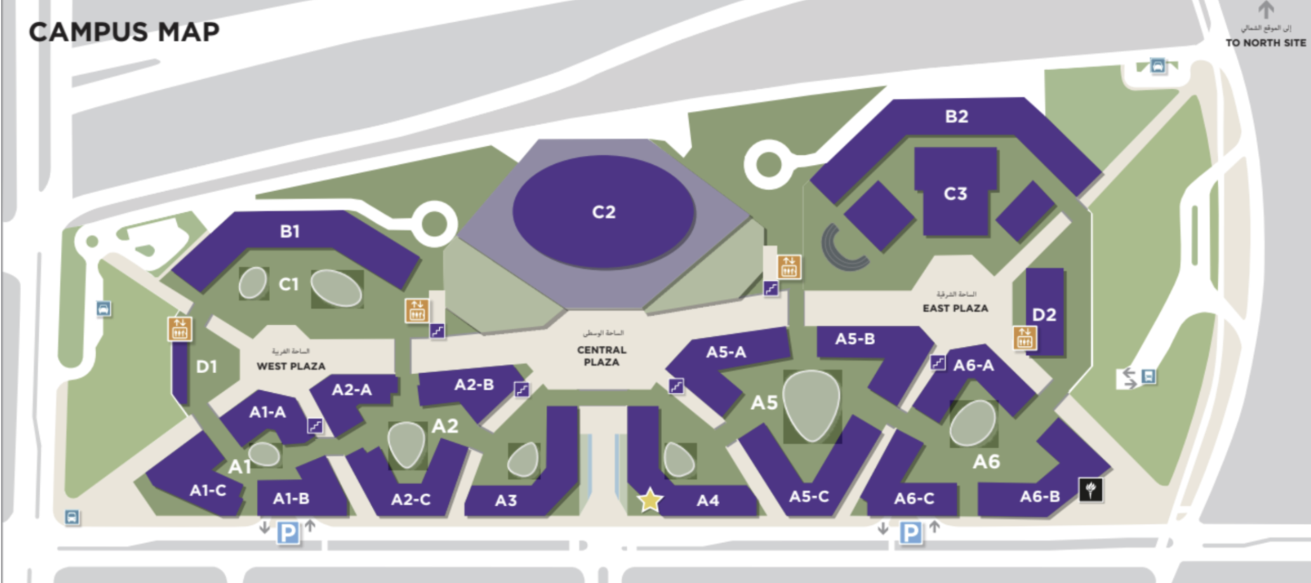
Since my midterm project was related to our campus, I wanted to work on something similar for the final project. I came up with the idea to create an interactive NYUAD campus explorer. I thought it would be a great project to showcase the beauty and resourcefulness of our campus.
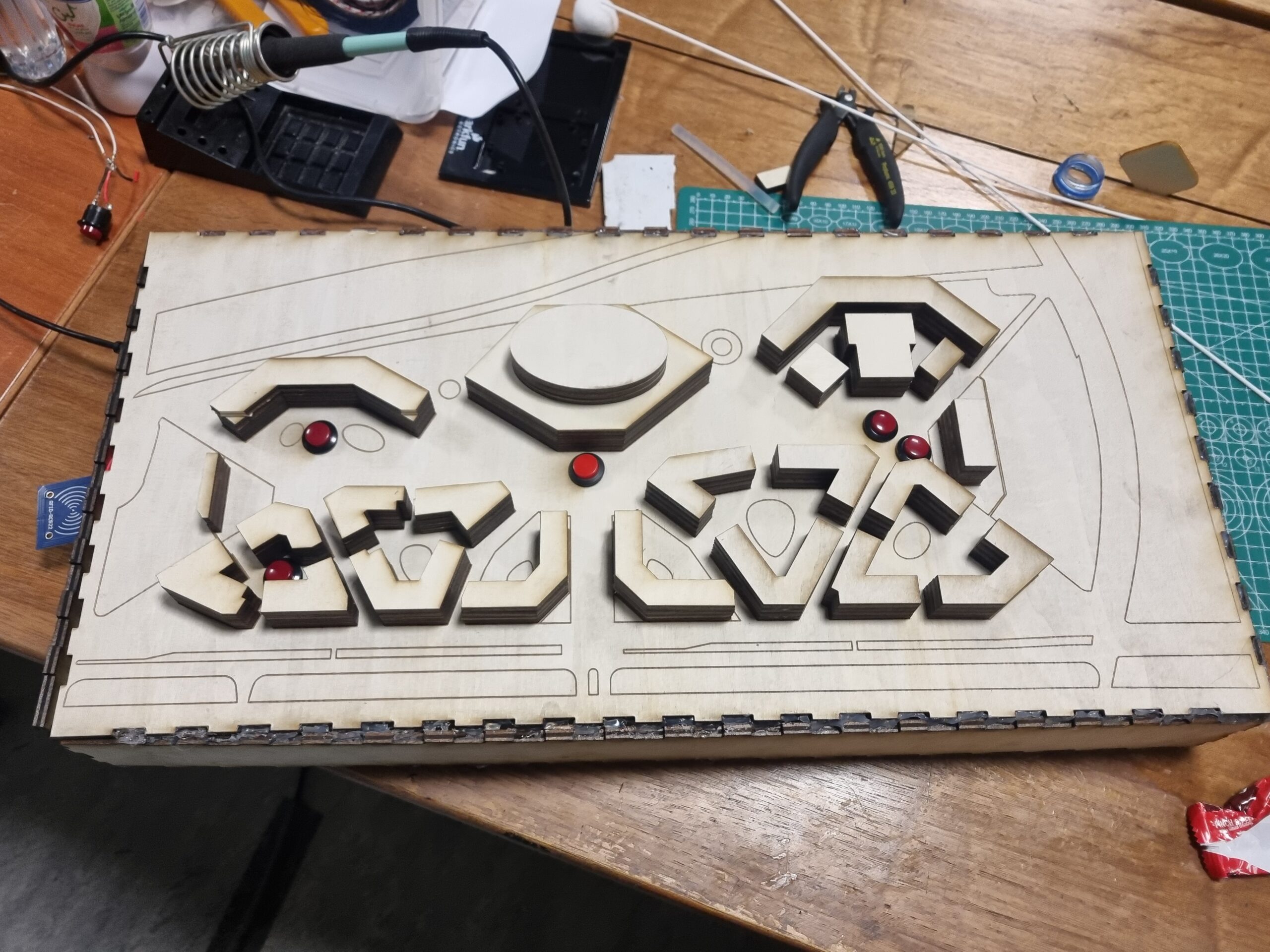
My project consists of a physical 3D model of our campus and a p5.js sketch that provides information about individual buildings.
https://editor.p5js.org/hk3863/full/5MT2OTbHL
Code
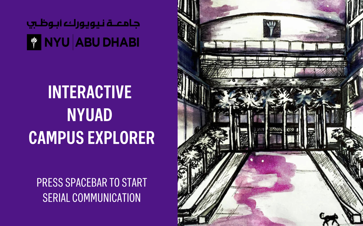
The first thing the user sees is the “MAINPAGE” function, where serial communication begins.
 background(mainpage)
  fill('white')
  textSize(width / 20);
  textAlign(CENTER, CENTER);
  textFont(boldFont);
  text("INTERACTIVE \nNYUAD \nCAMPUS EXPLORER", width / 4, height / 2);

  textSize(width / 30)
  textFont(regularFont);
  mainpage_message = "PRESS SPACEBAR TO START \nSERIAL COMMUNICATION"
  text(mainpage_message, width / 4, height / 1.2);

  if (serialcommunication == "TRUE") {
    mainpage_message = "CLICK TO START";
  }
}
Afterward, the user sees the ID explanation page, where the narrator welcomes them to NYUAD and explains how the virtual tour works. I used the subscription logic from this source (https://editor.p5js.org/hk3863/sketches/OSSNouhkg ), but I’ve adjusted the texts and timings to fit my project.
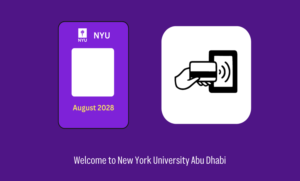
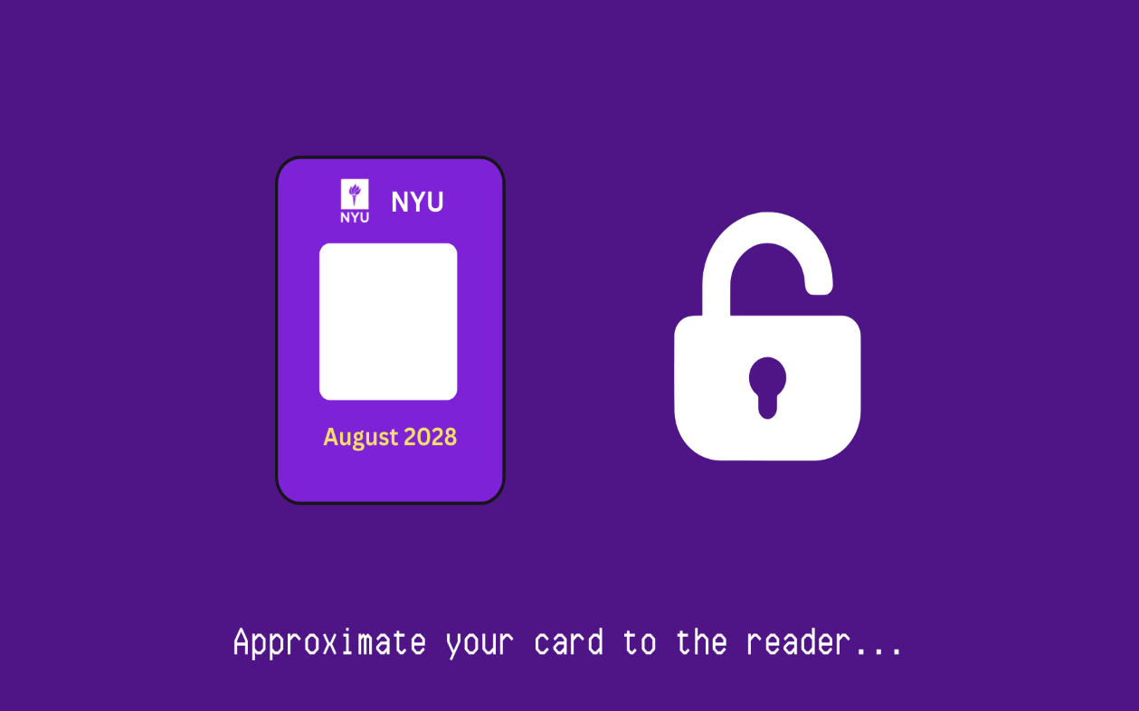
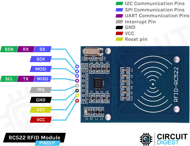
An essential and creative aspect of this project is the NYU ID card, which is required to access buildings on the NYUAD campus. I’ve used an RFID sensor to replicate the ID card.
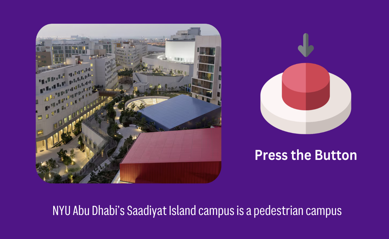
When the user clicks on the page, they’re taken to the instruction page, where they can press buttons for specific buildings to obtain information. Here’s the interesting part: after pressing a button, they must scan their ID card to access the information, just as they would when using their ID card to enter buildings.
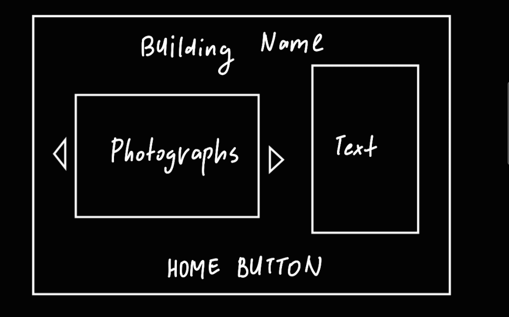
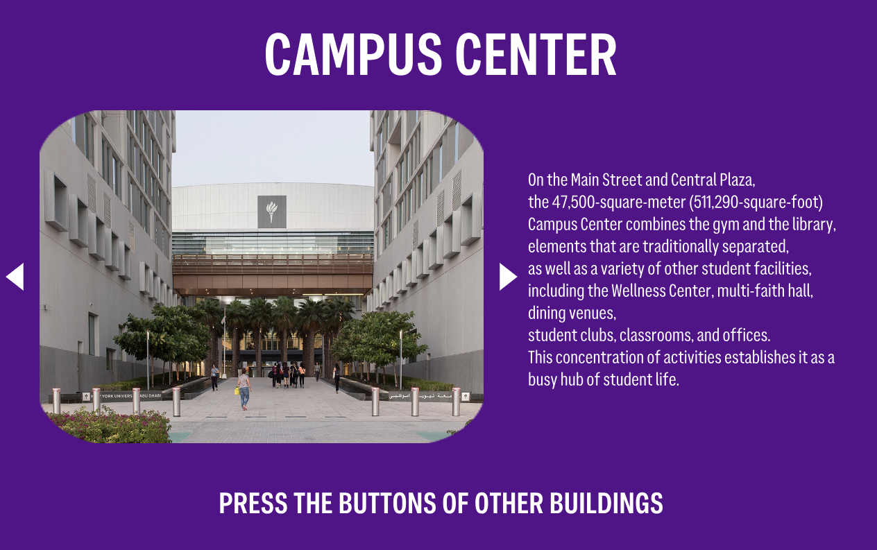
 My model includes five buttons, each linked to a page with information about a building: Campus Center, Dining Halls, Research Buildings, Residences, and the Arts Center. Each page includes photographs and buttons to navigate to the next or previous photo.
function information() {

  background(87, 6, 140);
  imageMode(CENTER);
  textAlign(CENTER, CENTER);

  textSize(width / 15)
  textFont(boldFont);
  text(title, width / 2, height / 12);
  image(photo[i], imageCenterX, imageCenterY, picturesWidth, picturesHeight);

  fill('white');
  noStroke();

  // Right Triangle Button
  triangle(rightXBase + width / 50, imageCenterY, rightXBase, imageCenterY - height / 40, rightXBase, imageCenterY + height / 40);

  // Left Triangle Button
  triangle(leftXBase - width / 50, imageCenterY, leftXBase, imageCenterY - height / 40, leftXBase, imageCenterY + height / 40);


  imageMode(CENTER);
  image(photo[i], width * 0.3, height * 0.5, picturesWidth, picturesHeight);

  textAlign(LEFT, CENTER);
  textSize(width / 50)
  textFont(regularFont);
  text(information_text, width * 0.6, height * 0.5)

  textAlign(CENTER, CENTER);
  textSize(width / 30);
  textFont(boldFont);
  text('PRESS THE BUTTONS OF OTHER BUILDINGS', width / 2, height * 0.9)

}
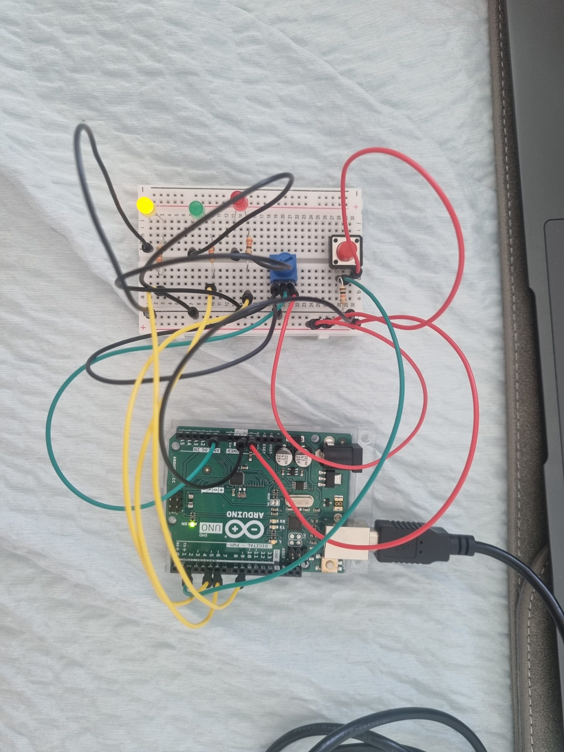
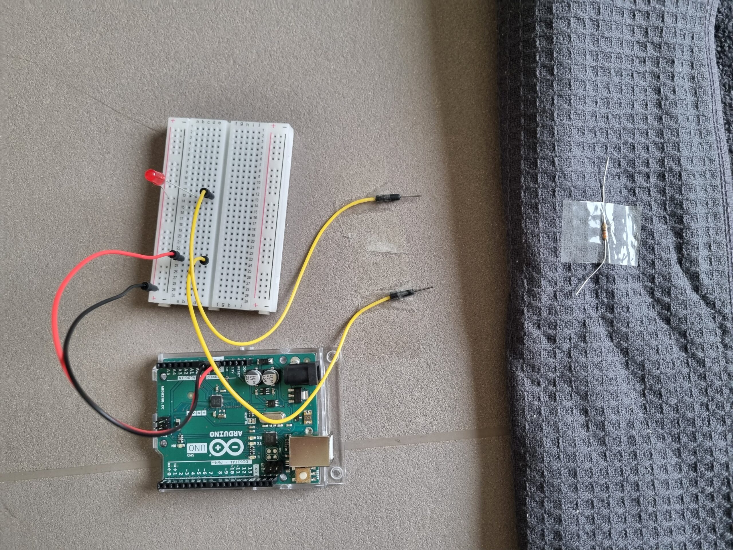
Arduino
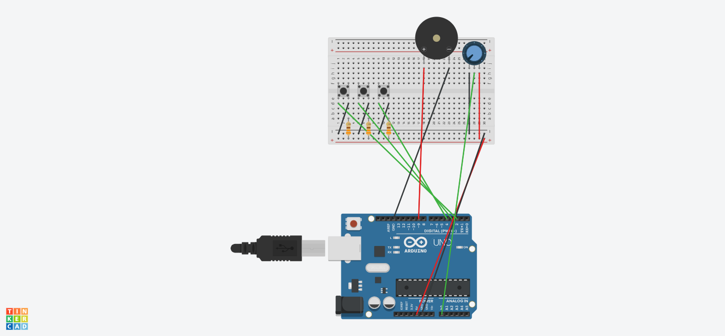
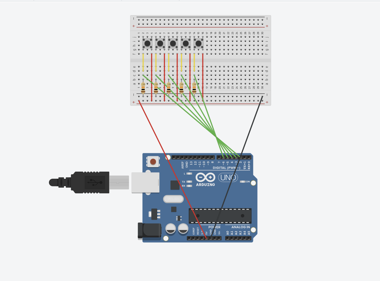
My Arduino code is sending two types of data. The first is the digital input from the buttons. I’ve created arrays so that when a specific button is pressed, the button number is sent to p5.js, which then triggers the relevant function about that particular building. The second data type comes from the RFID sensor. I watched several tutorials on YouTube to understand how RFID works. In my code, you’ll see that when the tag name of my card is detected by the RFID sensor, the sensor sends a “1” to p5.js, granting access to the information.
#include <SPI.h>
#include <MFRC522.h>
// RFID Setup
#define SS_PIN 10
#define RST_PIN 9
MFRC522 mfrc522(SS_PIN, RST_PIN); // Create MFRC522 instance
// Button Setup
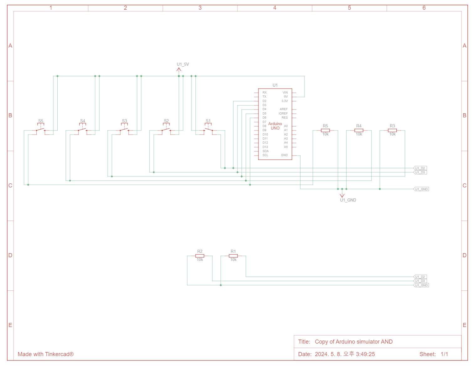
const int buttonPins[] = {2, 3, 4, 5, 6}; // Digital pins for buttons
const int numButtons = sizeof(buttonPins) / sizeof(buttonPins[0]);
bool lastButtonState[numButtons] = {0};
// RFID Access Card UID
const String AUTHORIZED_CARD_UID = "70 91 42 55";
bool isAuthorized = false;
int cardAccessStatus = 0;
int buttonPressed = -1;
void setup() {
// Initialize Serial Communication
Serial.begin(9600);
// Initialize RFID Reader
SPI.begin();
mfrc522.PCD_Init();
// Initialize Button Pins (Input Mode, assuming external pull-down resistors)
for (int i = 0; i < numButtons; i++) {
pinMode(buttonPins[i], INPUT);
}
}
void loop() {
// Check RFID Access
checkRFID();
// Process Button Presses
checkButtons();
// Send Combined Data
Serial.print(buttonPressed);
Serial.print(",");
Serial.println(cardAccessStatus);
// Reset button state only if no button is currently pressed
if (buttonPressed != -1) {
buttonPressed = -1;
}
delay(100); // Debounce delay
}
void checkRFID() {
// Look for new cards
if (!mfrc522.PICC_IsNewCardPresent()) {
return;
}
// Select one of the cards
if (!mfrc522.PICC_ReadCardSerial()) {
return;
}
// Show UID on Serial Monitor
String content = "";
for (byte i = 0; i < mfrc522.uid.size; i++) {
content.concat(String(mfrc522.uid.uidByte[i] < 0x10 ? " 0" : " "));
content.concat(String(mfrc522.uid.uidByte[i], HEX));
}
content.toUpperCase();
Serial.println("UID tag: " + content);
// Check if the card is authorized
if (content.substring(1) == AUTHORIZED_CARD_UID) {
isAuthorized = true;
cardAccessStatus = 1; // Set to 1 for authorized access
isAuthorized = false;
} else {
isAuthorized = false;
cardAccessStatus = 0; // Set to 0 for denied access
}
}
void checkButtons() {
for (int i = 0; i < numButtons; i++) {
// Button logic without pull-ups: HIGH = Button pressed
bool currentButtonState = digitalRead(buttonPins[i]) == HIGH;
if (currentButtonState != lastButtonState[i]) {
lastButtonState[i] = currentButtonState;
if (currentButtonState) {
buttonPressed = i; // Store the pressed button index
}
}
}
}
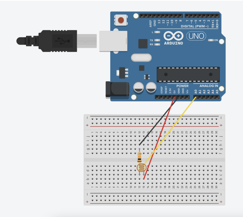
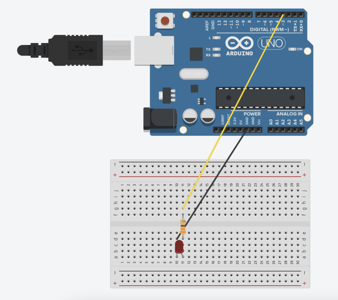
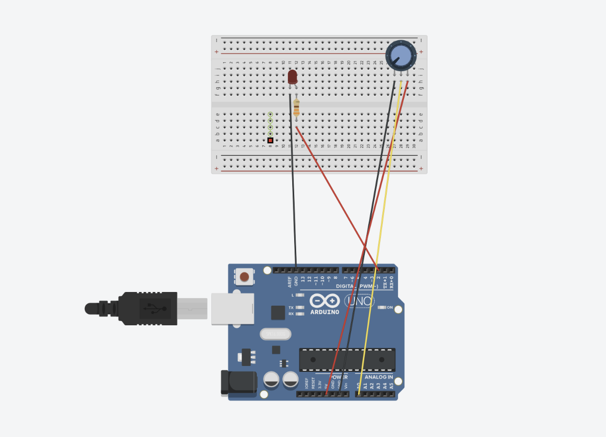
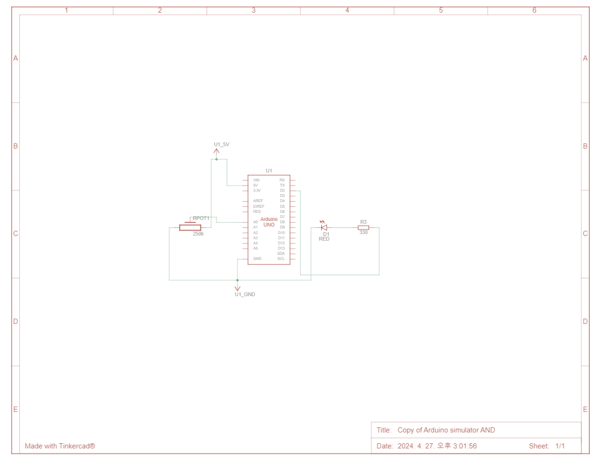
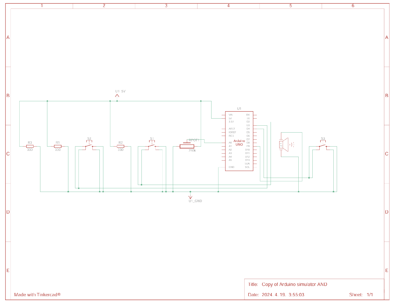
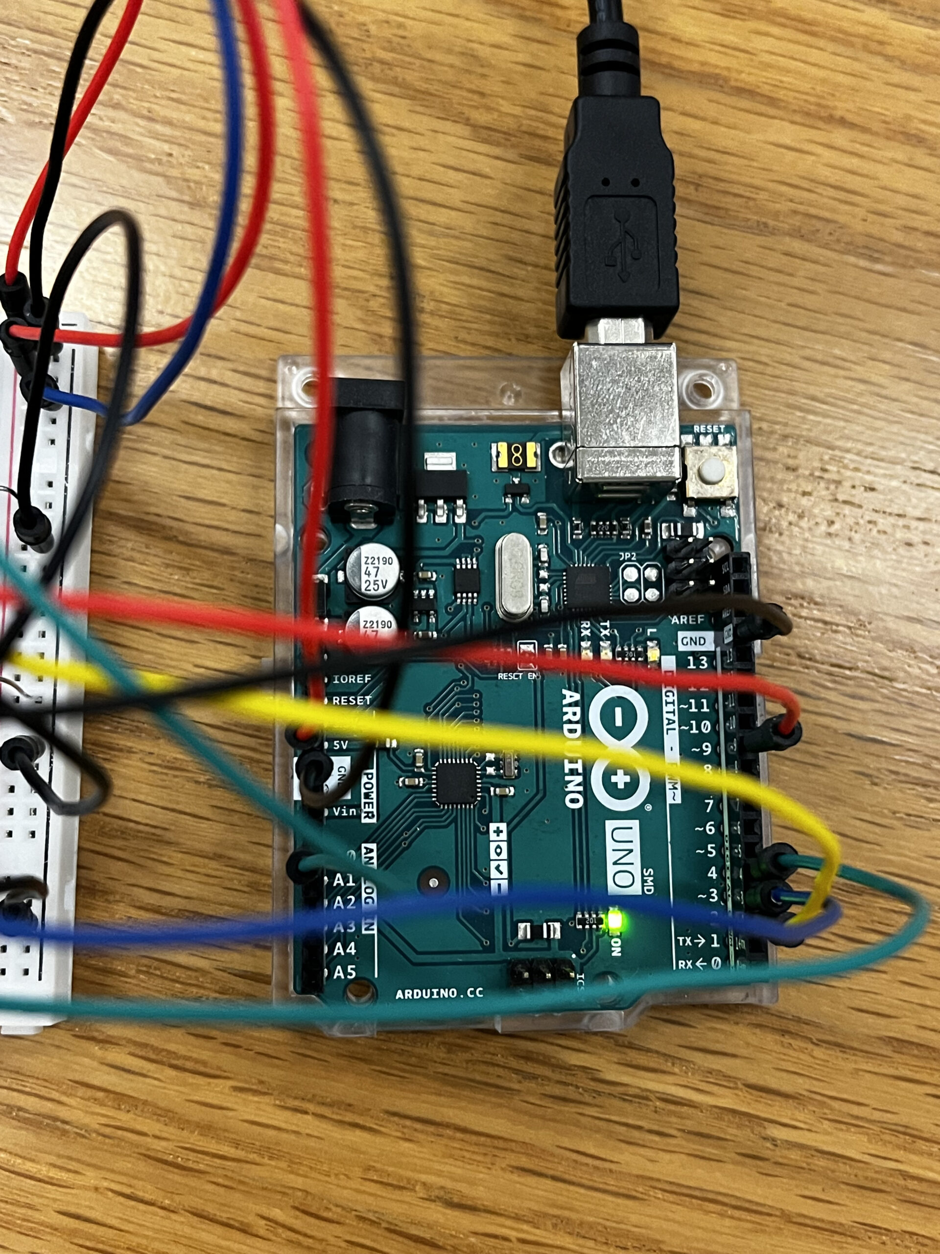
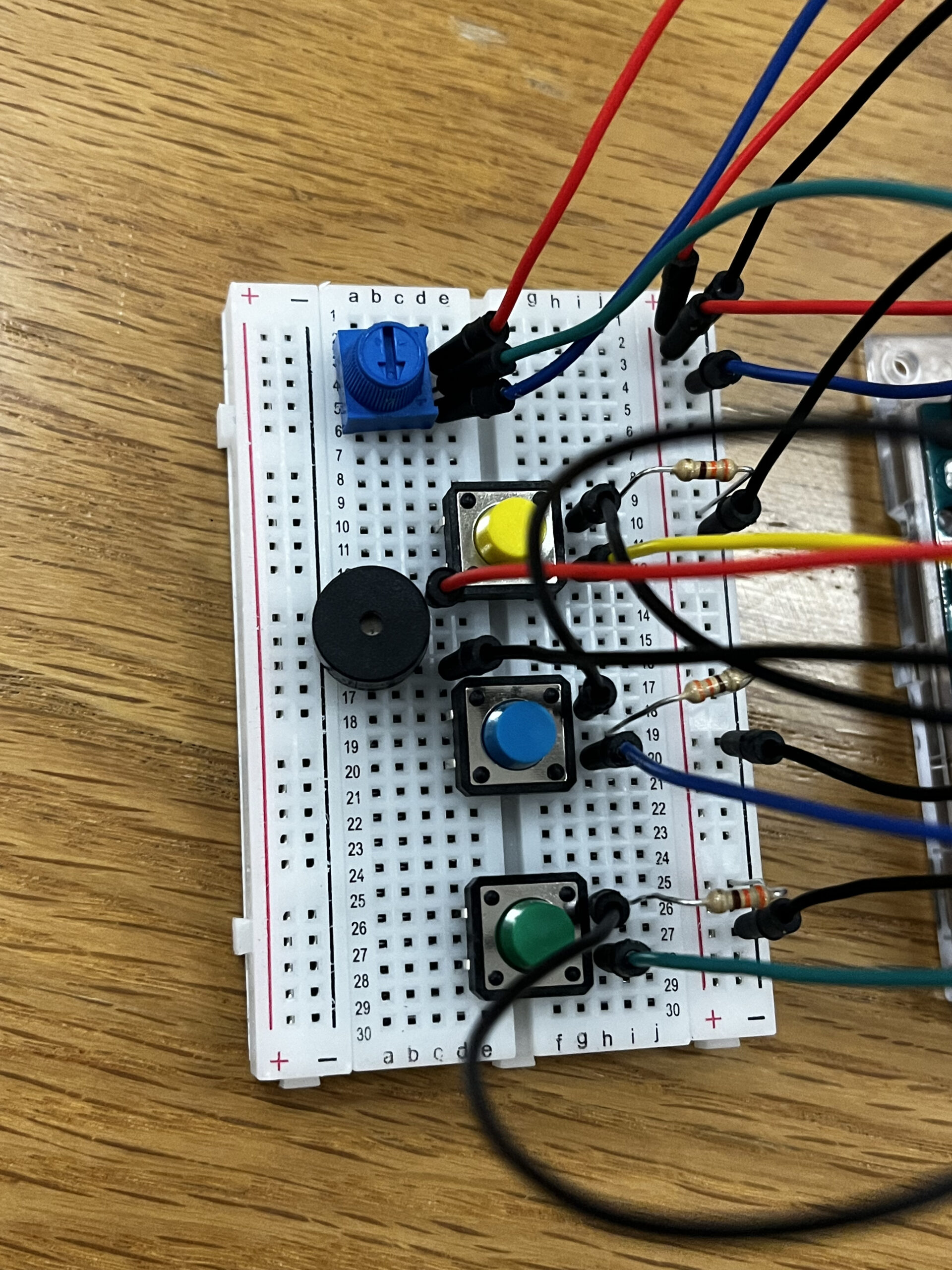
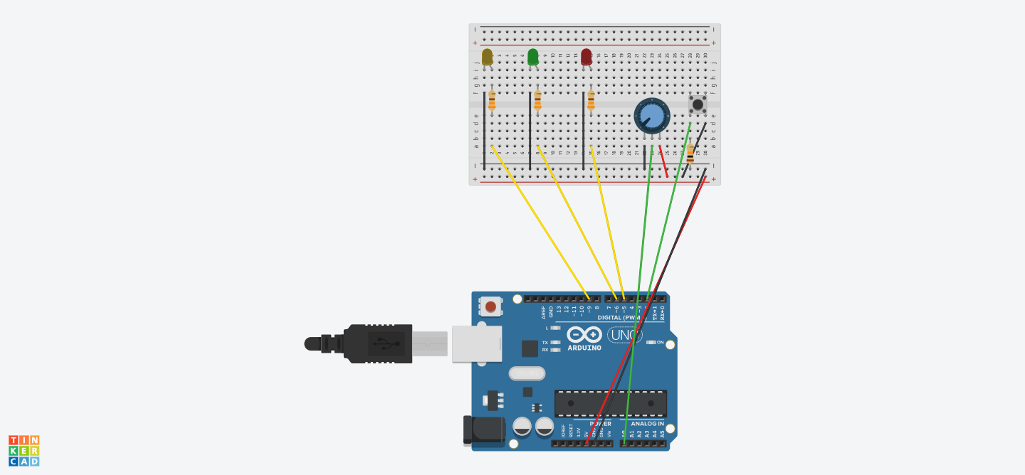
Circuit
What I Am Proud Of
I am particularly proud of creating the physical 3D model. It was my first time using Illustrator and laser cutting, and it was exciting to see the results. Through this project, I learned how to use Illustrator to turn my ideas into reality. Additionally, I’m happy I tried using a new sensor (RFID), which wasn’t covered in class. I believe it aligns well with the project’s concept.
Further Improvements
Because I didn’t have enough time, I couldn’t paint the campus model. However, with more time, I believe I could have made this model much more beautiful. Additionally, I couldn’t include information about some buildings, such as D1, so I decided to combine D2 and D1.
Overall, I am satisfied with the project’s outcome and pleased that I tried several new things and learned so much from this experience.
IM Show
A lot of people came to see my project! I really enjoyed the experience of presenting my work to others. Through this, I was able to identify some bugs I hadn’t noticed before. People loved the 3D model of the campus I created. They suggested it could be used for Marhaba or campus tours.