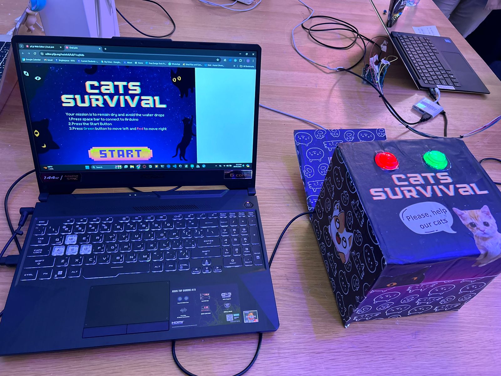
Concept:
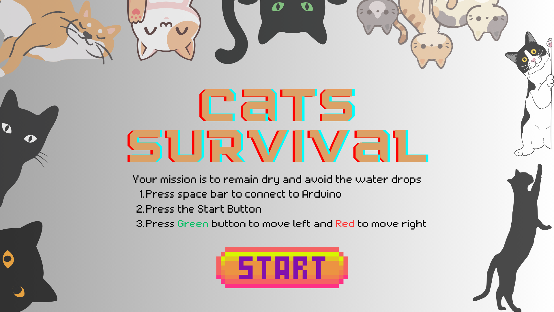
My inspiration for this project was one questions I have asked myself really often during the rainy days: “Where do the campus cats go?” and “How do they survive the rain?”. Based on this, I created “CATS SURVIVAL”, inspired also by the classic arcade games where players navigate through obstacles to achieve a high score. In this game, players engage with Arduino push buttons to control the cat attempting to avoid falling water drops while traversing a colorful campus setting.
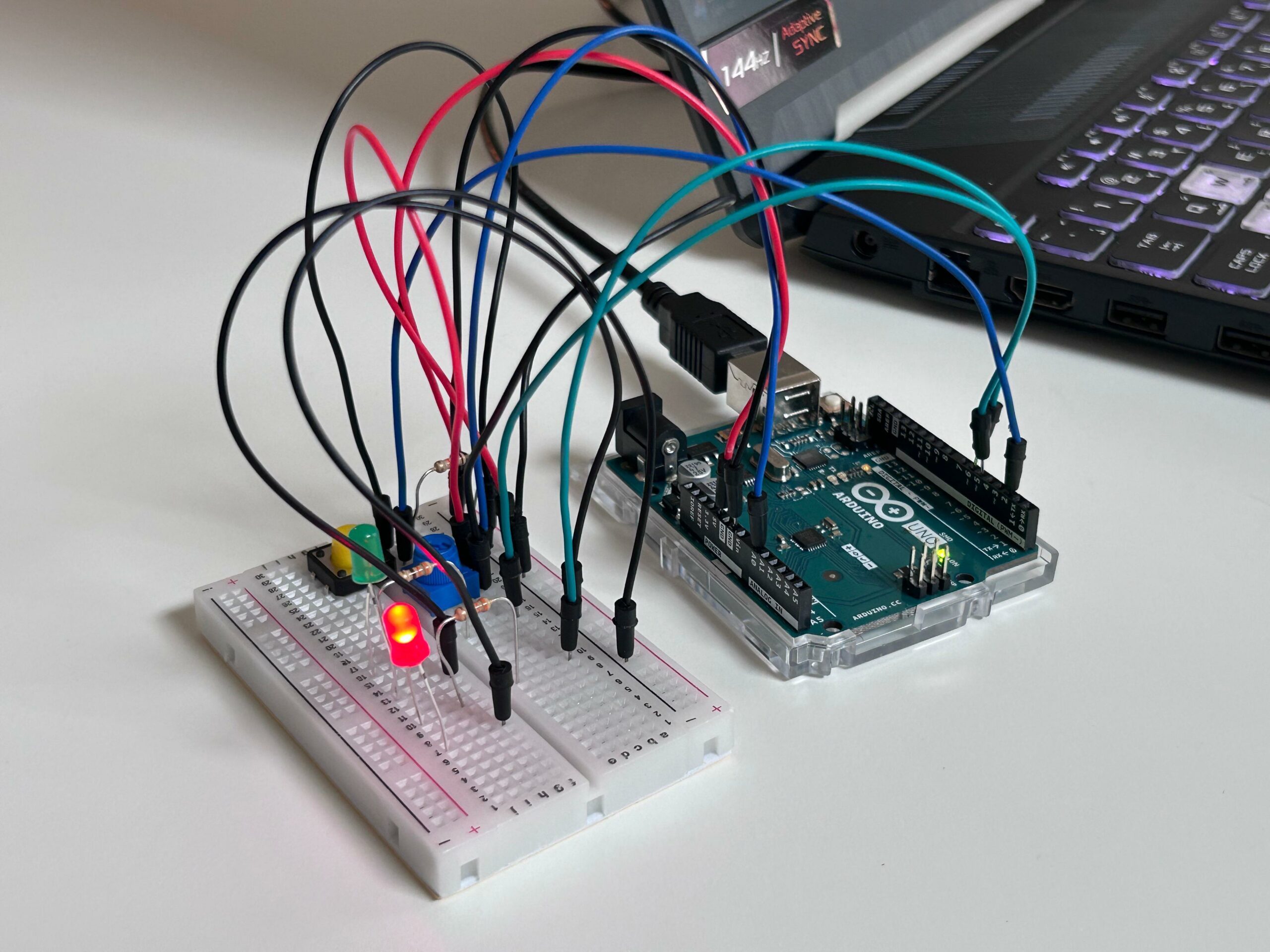
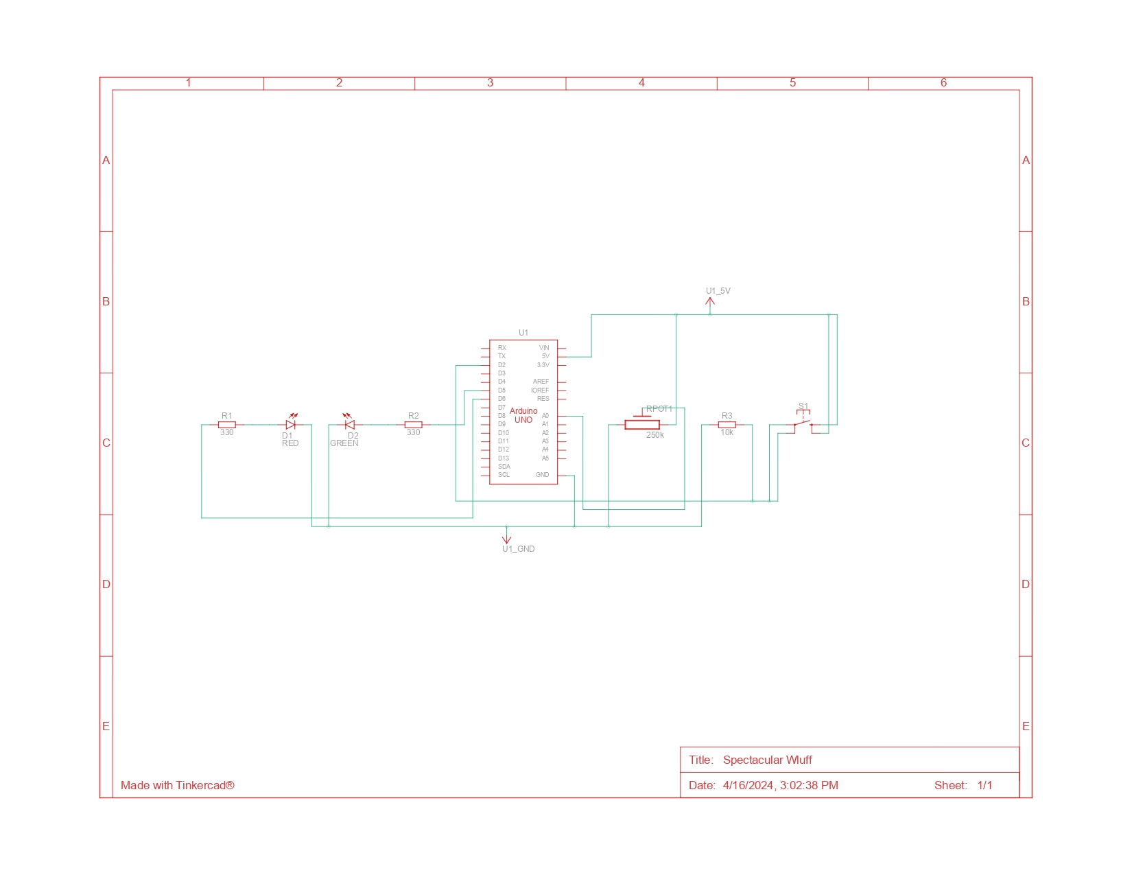
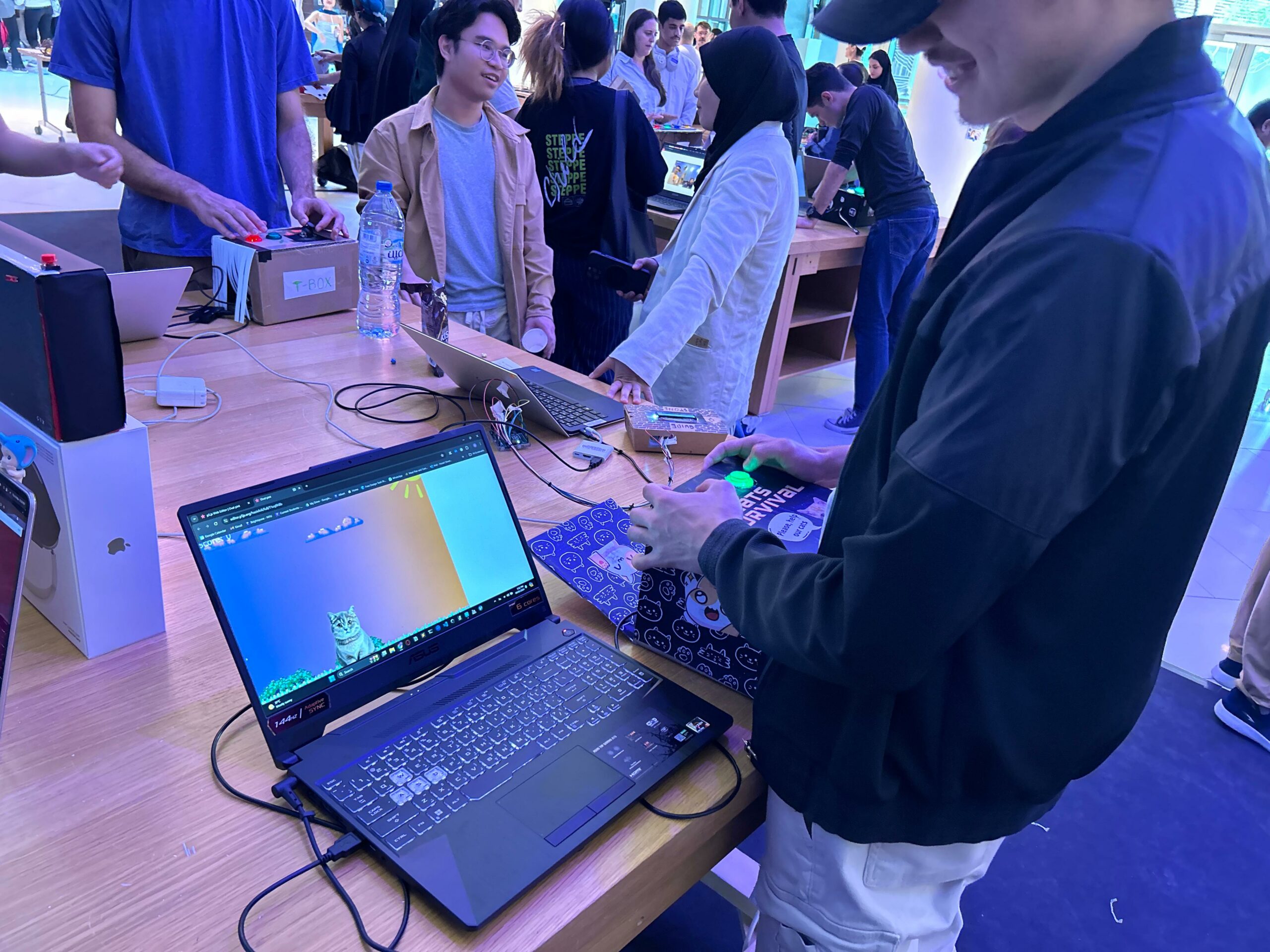
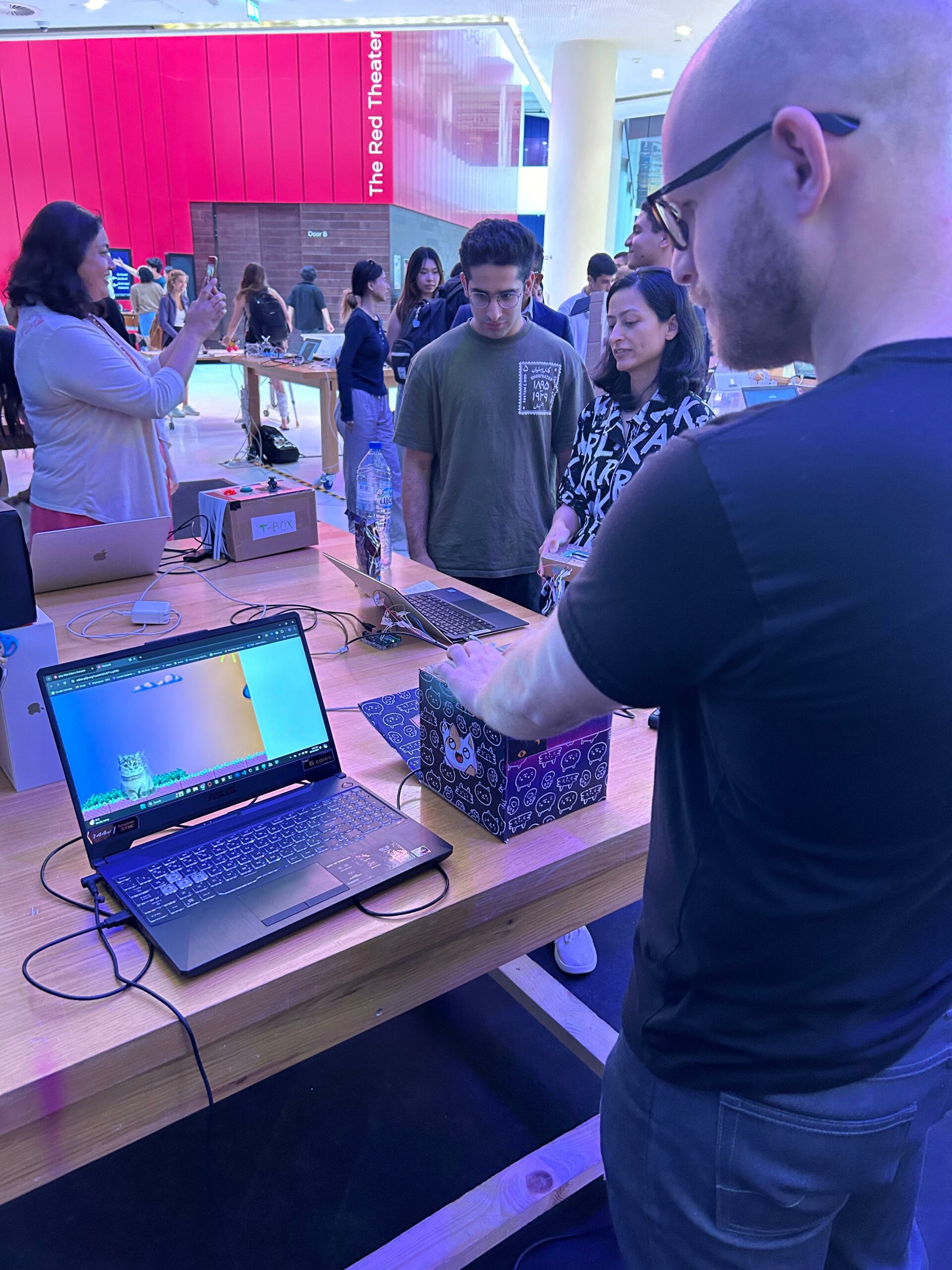
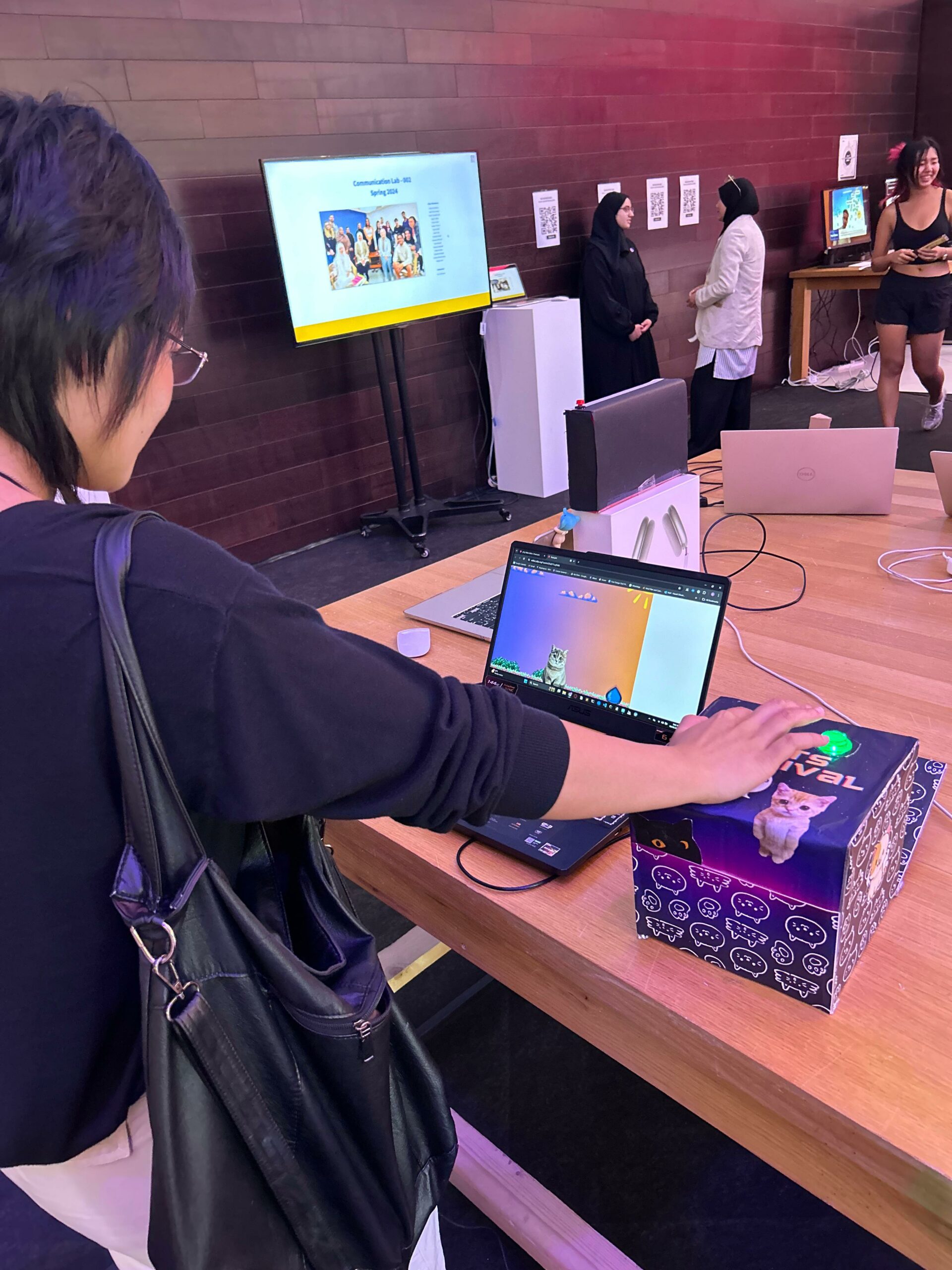
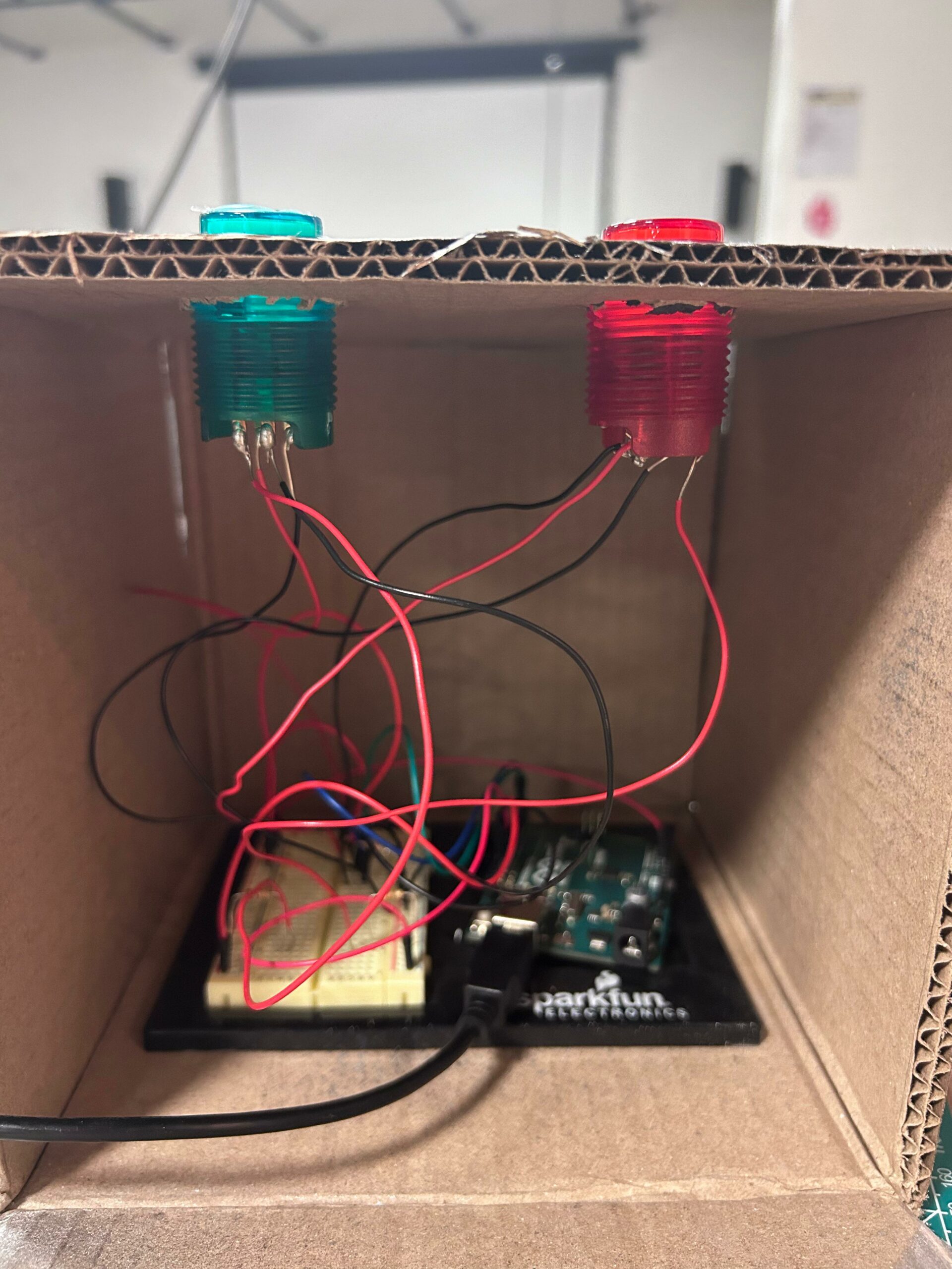
Final Setup:
IM Showcase:
How it works:
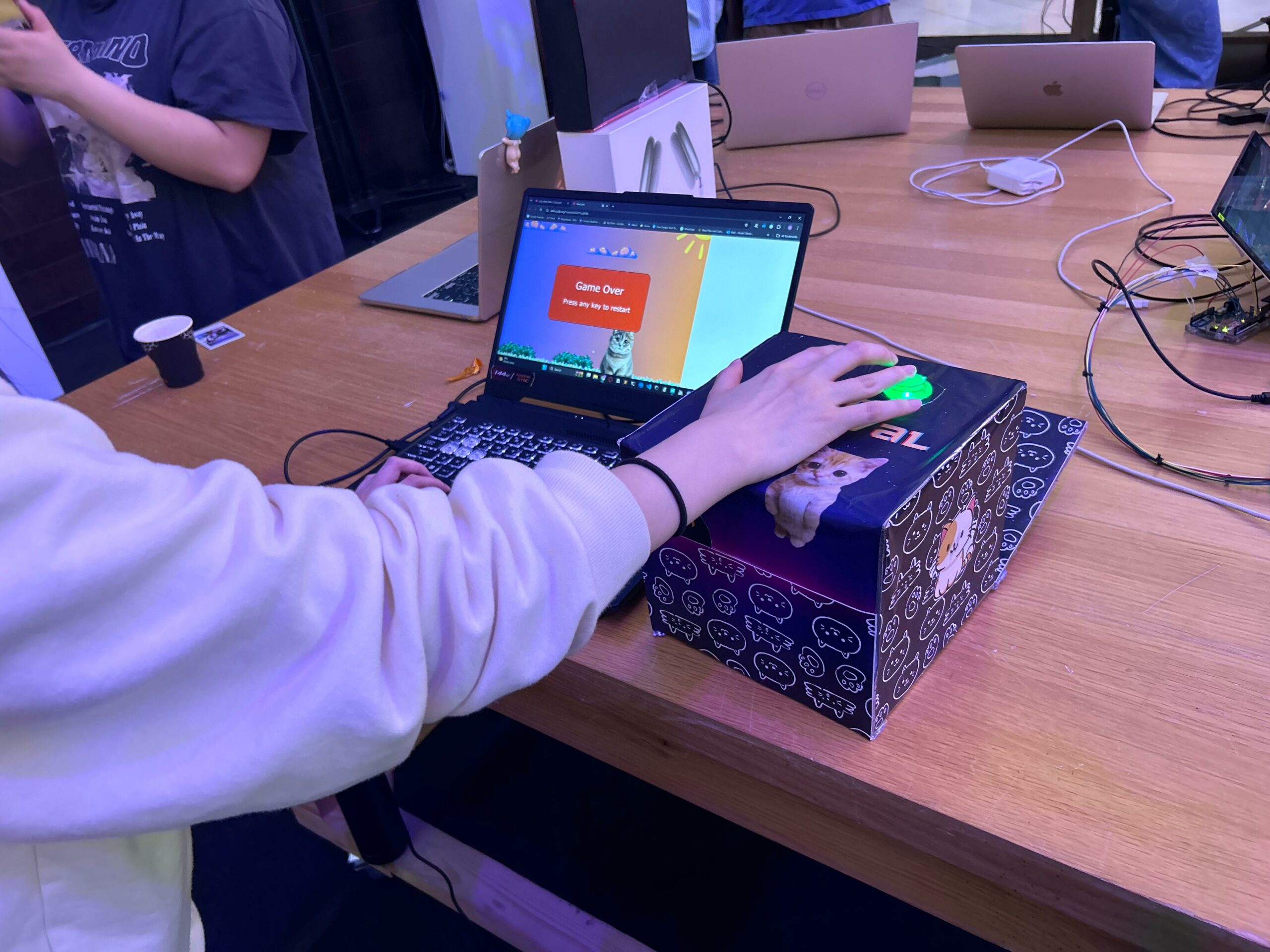
Players start by launching the game, where they are greeted with a vibrant start page featuring the game’s logo. Once the game begins, the cat automatically appears at the center of the screen, and the player’s objective is to keep the cat from being hit by falling water drops.
Using a connected serial input device (Arduino), players can move the cat left or right, dodging incoming obstacles. Each successful dodge increases the player’s score, while collision with a water drop ends the game.
As the game progresses, the speed, and frequency of falling water drops increase, challenging the player’s reflexes and agility. Upon game over, players can restart the game by pressing any key, offering them the opportunity to beat their previous high score and continue the thrilling dodge-and-survive gameplay.
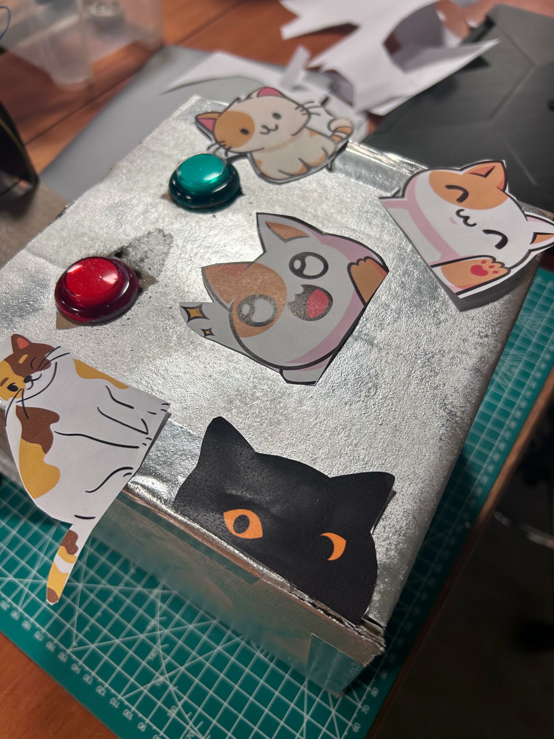
Images of the project (1st draft):
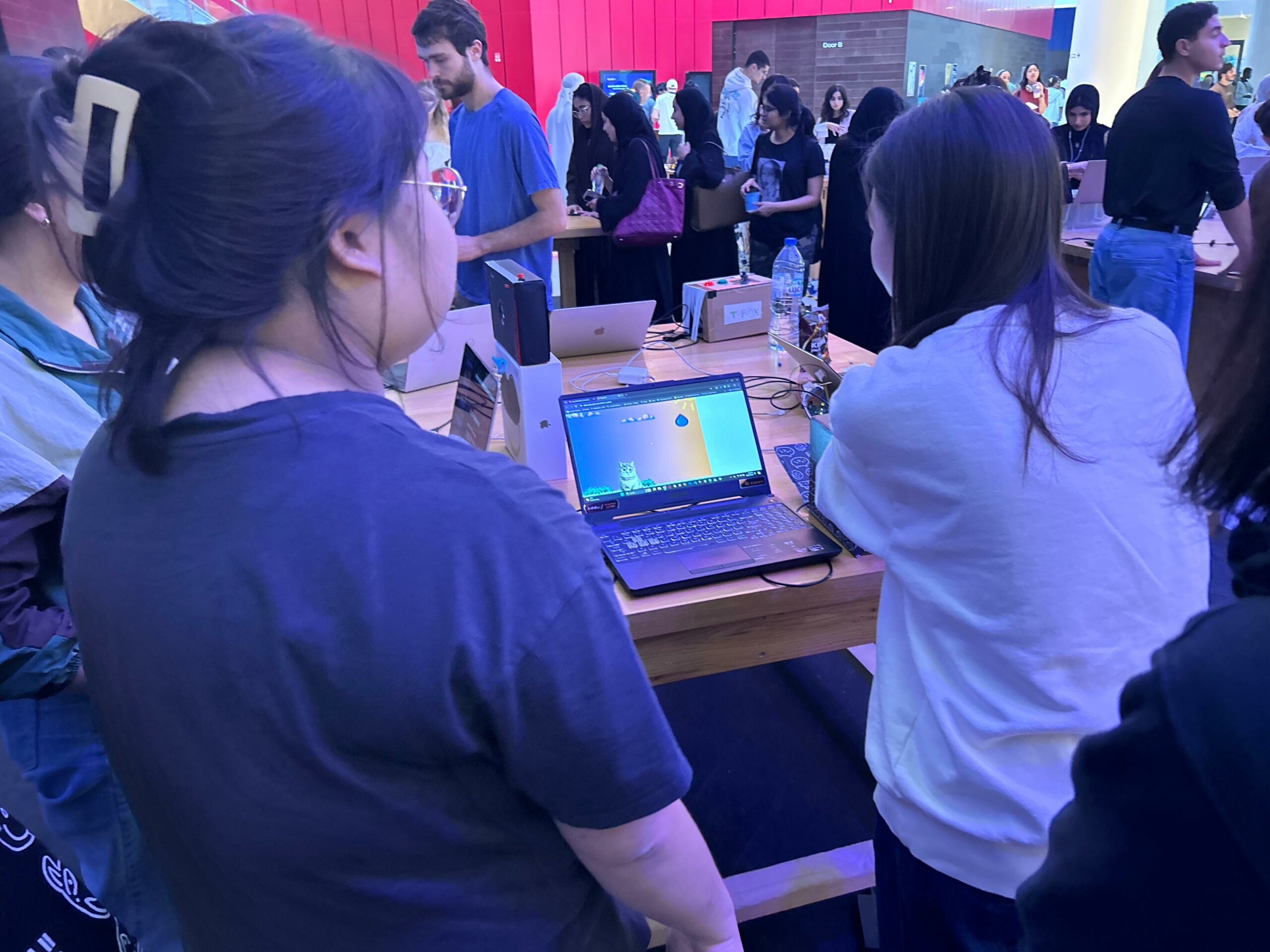
User testing:
p5 Game:
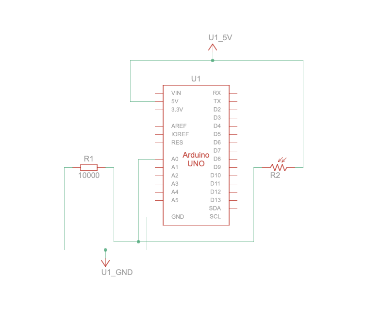
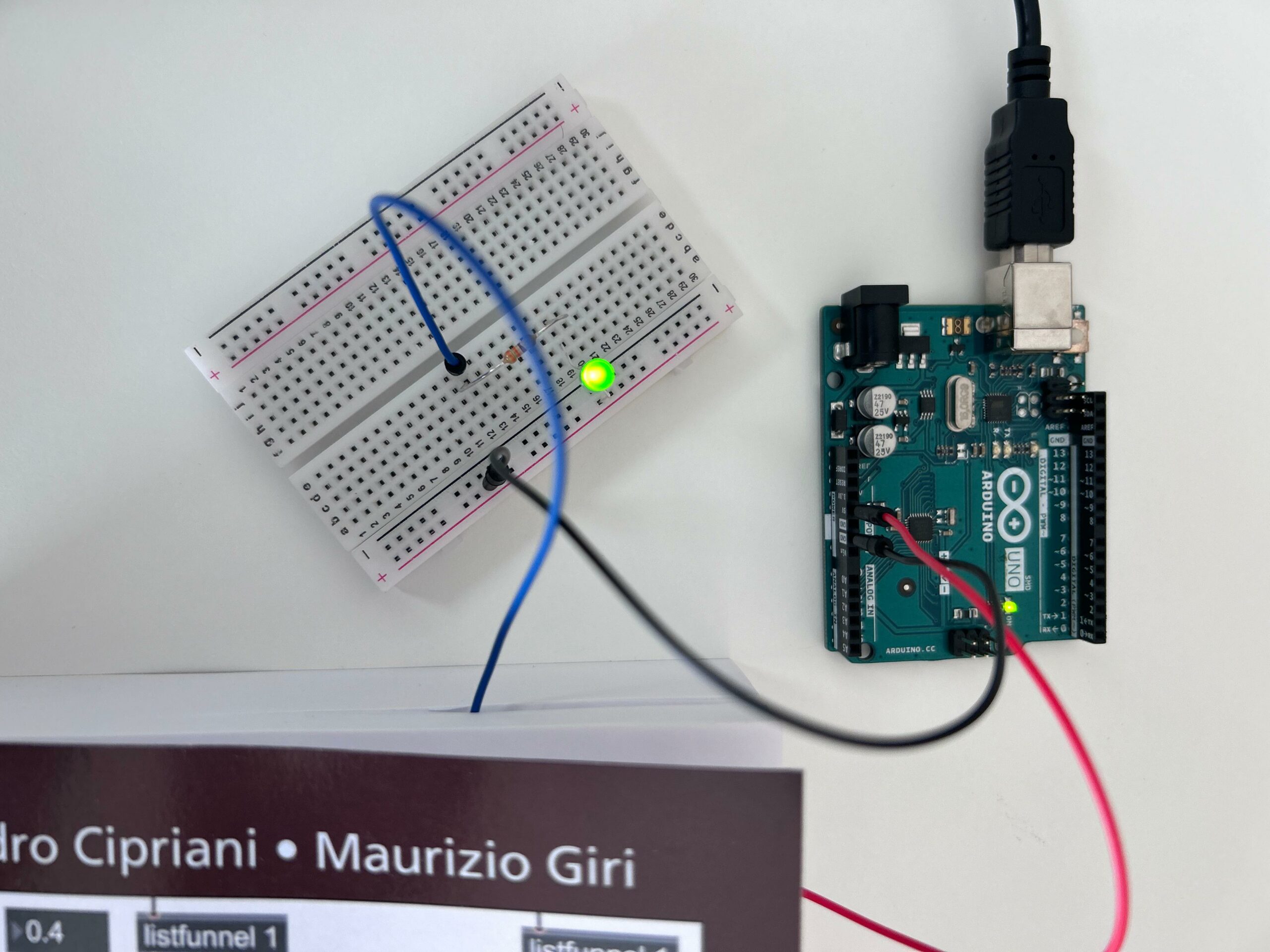
Arduino Code:
// Constants won't change. They're used here to set pin numbers:
const int buttonPin1 = 2;  // The number of the first pushbutton pin
const int buttonPin2 = 3;  // The number of the second pushbutton pin
const int ledPin1 = 13;    // The number of the first LED pin
const int ledPin2 = 12;    // The number of the second LED pin

// Variables will change:
int buttonState1 = 0;  // Variable for reading the first pushbutton status
int buttonState2 = 0;  // Variable for reading the second pushbutton status

void setup() {
  // Initialize the LED pins as outputs:
  pinMode(ledPin1, OUTPUT);
  pinMode(ledPin2, OUTPUT);

  // Initialize the pushbutton pins as inputs:
  pinMode(buttonPin1, INPUT_PULLUP); // Changed to INPUT_PULLUP
  pinMode(buttonPin2, INPUT_PULLUP); // Changed to INPUT_PULLUP

  // Start serial communication:
  Serial.begin(9600);
}

void loop() {
  // Read the state of the first pushbutton value:
  buttonState1 = digitalRead(buttonPin1);

  // Check if the first pushbutton is pressed. If it is, the buttonState is LOW:
  if (buttonState1 == LOW) {
    // Turn the first LED on:
    digitalWrite(ledPin1, HIGH);
  } else {
    // Turn the first LED off:
    digitalWrite(ledPin1, LOW);
  }

  // Read the state of the second pushbutton value:
  buttonState2 = digitalRead(buttonPin2);

  // Check if the second pushbutton is pressed. If it is, the buttonState is LOW:
  if (buttonState2 == LOW) {
    // Turn the second LED on:
    digitalWrite(ledPin2, HIGH);
  } else {
    // Turn the second LED off:
    digitalWrite(ledPin2, LOW);
  }

  // Send button states to the p5 sketch
  Serial.print(buttonState1);
  Serial.print(",");
  Serial.println(buttonState2);
  delay(100); // Adjust delay as needed
}
p5 snippet code:
Reading serial data
This function reads data from the serial port, interprets it as button states, and updates the cat’s position accordingly. It ensures that the cat remains within the canvas bounds while moving left or right based on the received data.
This snippet demonstrate how the game can interact with an Arduino board via serial communication to control the cat’s movement.
function readSerial(data) {
  if (data != null) {
    let buttonStates = split(trim(data), ',');
    let buttonState1 = int(buttonStates[0]);
    let buttonState2 = int(buttonStates[1]);

    // Update cat position based on button states
    if (buttonState1 == 1) {
      catX -= 22; // Move left
    }
    if (buttonState2 == 1) {
      catX += 22; // Move right
    }

    // Ensure cat stays within canvas bounds
    catX = constrain(catX, 0, width - catImg.width);
  }
}
Challenges:
The challenge of this game is designing the obstacle mechanics to appropriately balance the game’s difficulty. Since the game operates in full-screen mode, ensuring that the falling obstacles provide a challenging, yet enjoyable experience for players can be tricky. Balancing factors such as the speed, frequency, and size of the obstacles requires careful consideration to prevent the game from becoming too easy or too difficult. Additionally, transitioning from the initial idea of using a potentiometer for input to utilizing two push buttons might pose challenges in terms of code adaptation and player control dynamics.
Future improvements:
- Enhance the complexity of the game mechanics and integrating additional features into the circuit in order to elevate the player experience. Adding new gameplay elements such as power-ups, varying obstacle patterns can provide players with more engaging challenges and keep them invested in the game for longer durations.
- Incorporating a speaker into the Arduino circuit to synchronize with button presses could add a wider dimension to the gameplay, enhancing immersion and feedback for players. By integrating sound effects or background music that reacts to player actions, such as cat movements and obstacle collisions, the overall gaming experience can be enriched, making it more dynamic and enjoyable.