Final Project – Interactive Glove

Concept:

My concept for the final presentation is the Interactive Glove: a completely different way of interacting with the computer. The idea behind this project comes from “A Brief Rant on the Future of Interaction Design”, where interaction with digital media is discussed and criticized. After thinking about it thoroughly, I imagined that the best way to innovate in the interaction field would be to use a medium that we commonly use, our hands, but in a way that will utilize the limbs differently.

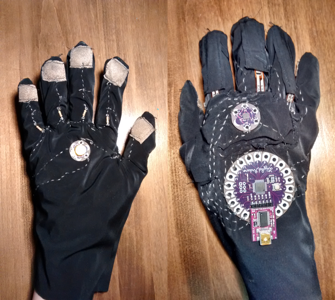
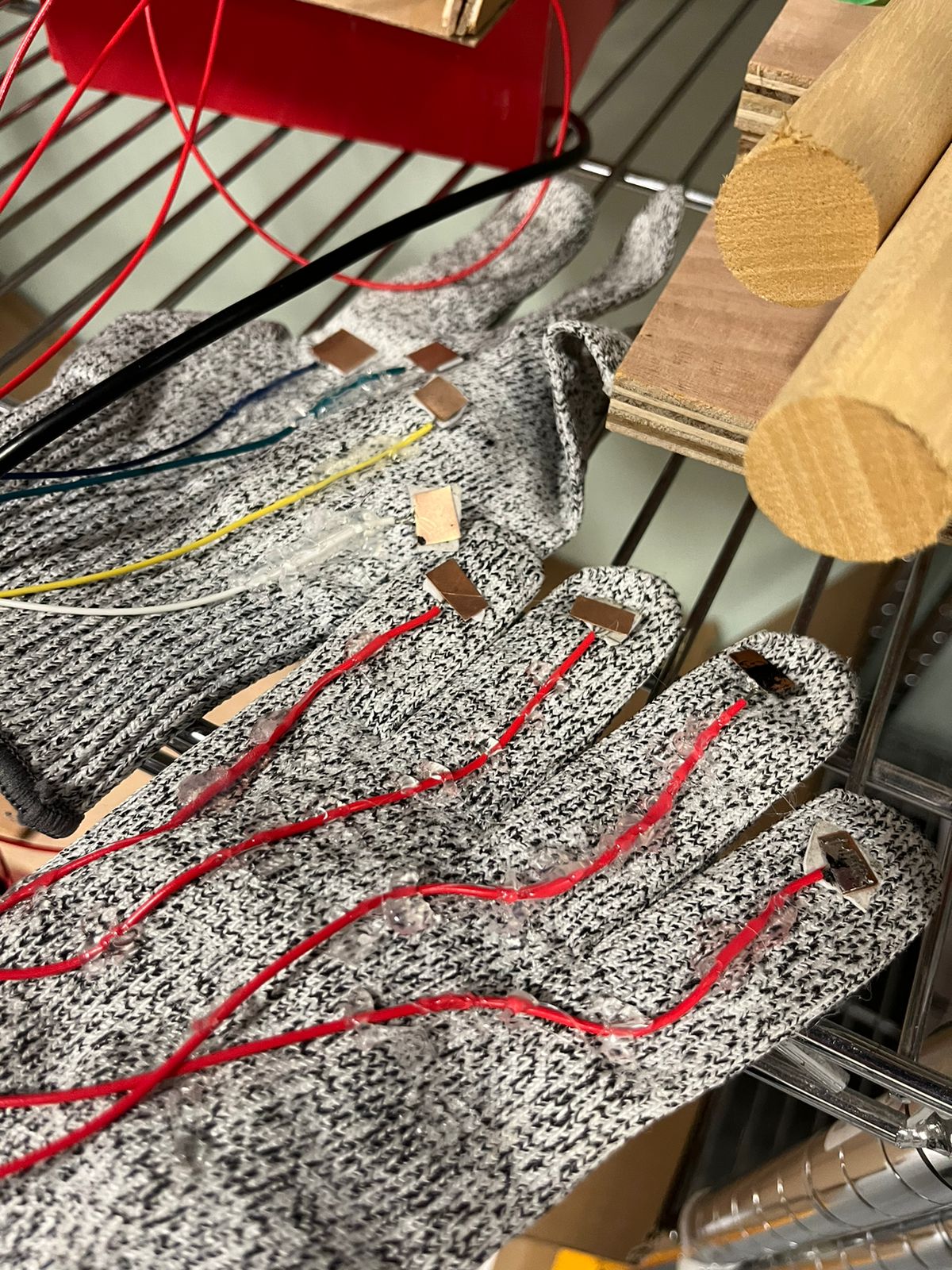
In this case, we can imagine the interactive glove as a binary system: we have 4 sensors in the left hand and 4 pins on the right hand that will turn on a sensor on contact. This allows for the user to have versatility in terms of how they want to use the glove. Some users will prefer to use one finger for all 4 sensors, while others might require 4 fingers for 4 sensors. Because it is a binary system, the glove can do anything: It can become a mouse, a keyboard, a switch, a controller, etc…

To show the versatility of this input method, we will use p5.js alongside some small games and experiences in order to show how the glove inputs values.

Implementation:

P5.js Sketch: https://editor.p5js.org/ff2185/sketches/A4mnwlg4h

Arduino code:

/*
  DigitalReadSerial

  Reads a digital input on pin 2, prints the result to the Serial Monitor

  This example code is in the public domain.

  https://www.arduino.cc/en/Tutorial/BuiltInExamples/DigitalReadSerial
*/

// digital pin 2 has a pushbutton attached to it. Give it a name:
int inputA = 2;
int inputB = 3;
int inputC = 4;
int inputD = 5;

// the setup routine runs once when you press reset:
void setup() {
  // initialize serial communication at 9600 bits per second:
  Serial.begin(9600);
  pinMode(LED_BUILTIN, OUTPUT);
  pinMode(inputA, INPUT);
  pinMode(inputB, INPUT);
  pinMode(inputC, INPUT);
  pinMode(inputD, INPUT);
  while (Serial.available() <= 0) {
    digitalWrite(LED_BUILTIN, HIGH);  // on/blink while waiting for serial data
    Serial.println("0,0");            // send a starting message
    delay(300);                       // wait 1/3 second
    digitalWrite(LED_BUILTIN, LOW);
    delay(50);
  }
}

// the loop routine runs over and over again forever:
void loop() {
  // print out the state of the button:// wait for data from p5 before doing something
  while (Serial.available()) {
    digitalWrite(LED_BUILTIN, HIGH);  // led on while receiving data
    if (Serial.read() == '\n') {
      // read the input pin:
      int stateA = digitalRead(inputA);
      int stateB = digitalRead(inputB);
      int stateC = digitalRead(inputC);
      int stateD = digitalRead(inputD);
      delay(5);
      int sensor2 = analogRead(A1);
      delay(5);
      Serial.print(stateA);
      Serial.print(',');
      Serial.print(stateB);
      Serial.print(',');
      Serial.print(stateC);
      Serial.print(',');
      Serial.println(stateD);
    }
  }
  digitalWrite(LED_BUILTIN, LOW);
  delay(1);  // delay in between reads for stability
}


Arduino:

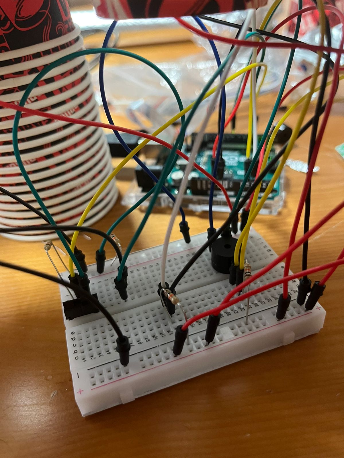
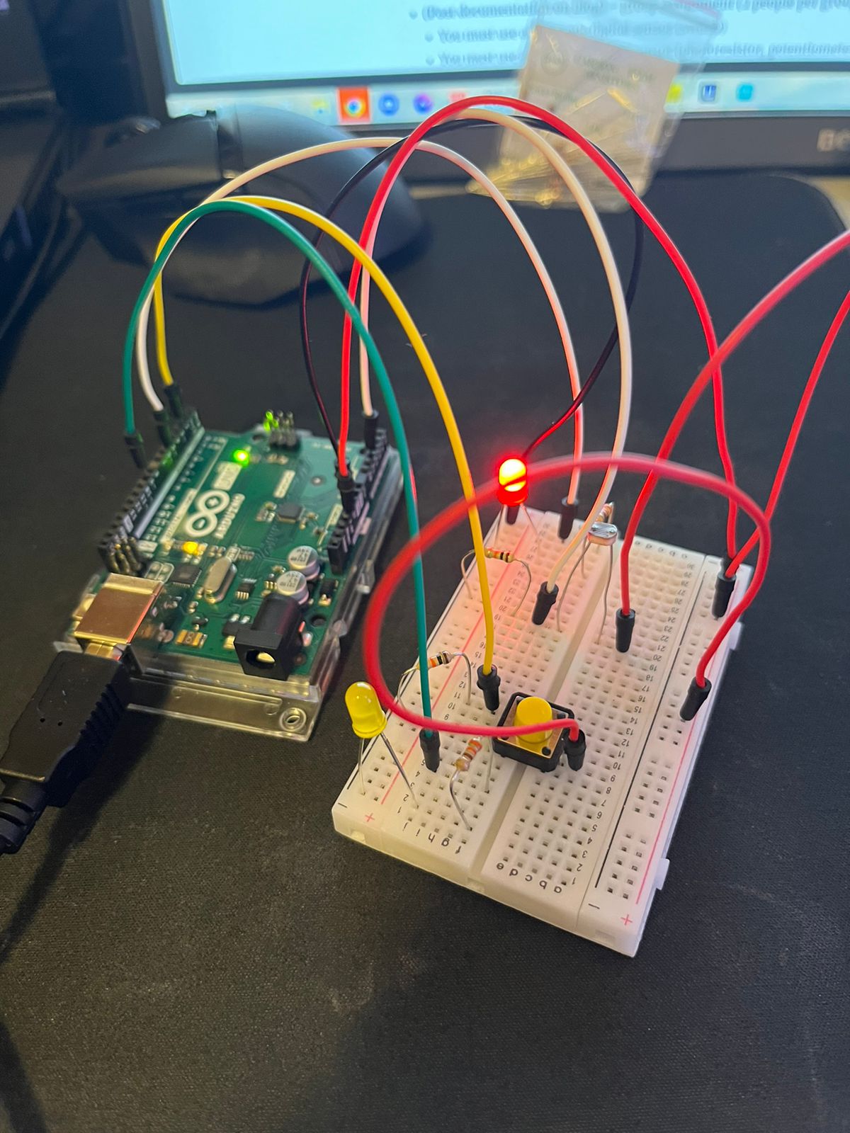
The Arduino Design is a simple switch system with 4 resistors connected to the ground, each connected to its proper pin and a cable which will be the connection to the 5v source. On the other side, we connected 4 cables to the 5v strip. This allows us to create a circuit in which any time 5v touches a cable that is on the other side, it will set the digitalInput of the pin to 1.

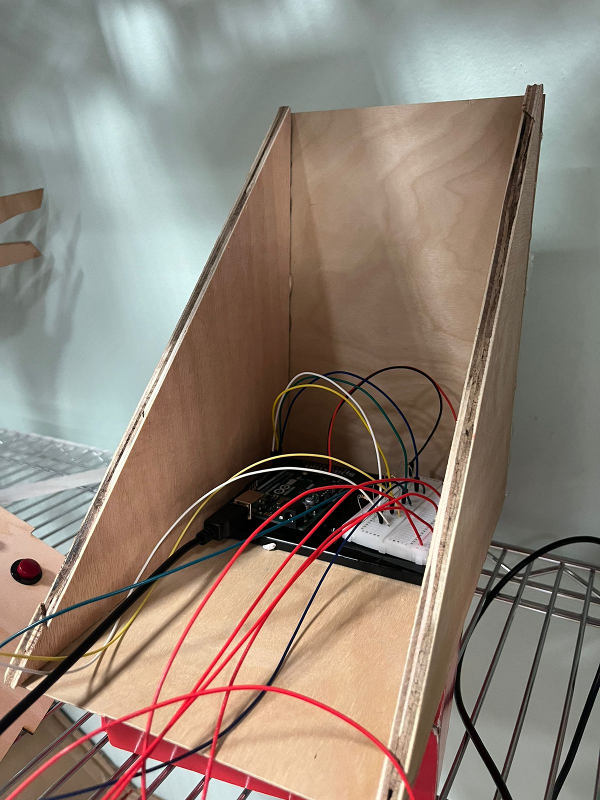
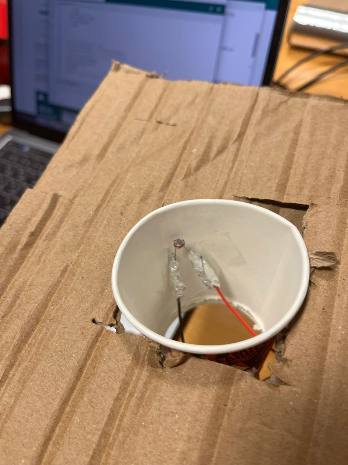
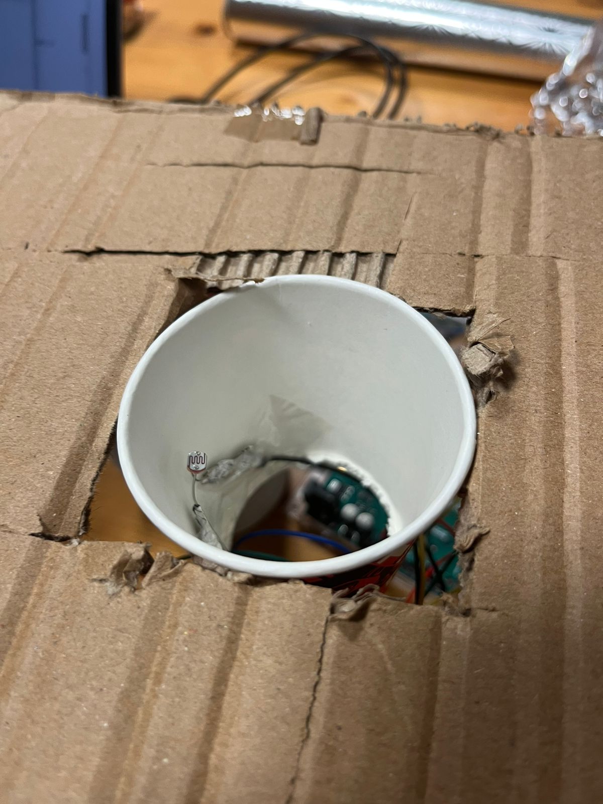
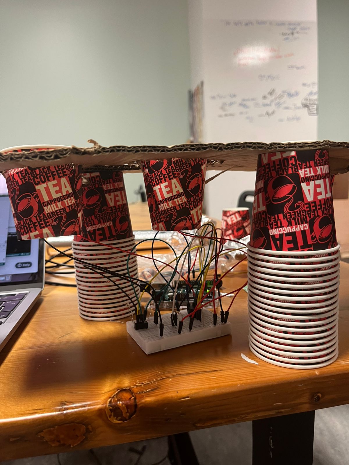
To cover the circuit, I handcrafted a “sandwich” shaped box that will allow the cables to move freely in the vertical axis. The biggest problem was to create an enclosure that would not disturb the cable movement. My idea, to not utilize the classic open top box, was to do this tringular enclosure that allows cables to move up and down freely. Due to the pure nature of the circuit itself, horizontal movement has to be limited in order to not disturb the functioning, so that is why movement is only constrained in the vertical axis

P5.js:

The P5.js sketch is a combination of past projects, examples provided by p5.js and other sketches I have gathered during my research. Each one of the experiences/games is a representation of different inputs styles: For example, the piano will behave differently based on the combination of fingers we press, while the rocket moves from left to right with the index and ring finger.

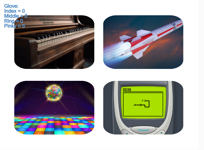
The available experiences are the following:

  • Piano: The piano experience is a recreation of a previous project. Back then, I utilized the keyboard in order to press the piano keys and generate the sound. This time, the gloves will do that function. Every key is mapped to a certain combination. For example. the “DO” note corresponds to touching just the index finger sensor. The following one is mapped to the middle finger, and so on until you will need to use two fingers. The input method shown here is converting the glove into a set of 2^4 inputs. In other words, a binary input.
  • Rocket: The Rocket Game involves long pressing a single sensor in order to fly the rocket up, go to the left or go to the right. There is no score, no timer, just you and a single fuel bar. Careful, if you go too low you will crash. Try your best to stay on air!
    This game simulates what it would be to use it as a mouse (the mouse clicks) to control the rocket.
  • Disco: The Disco experience is simple. Out of the 4 buttons you press, each of them will show a different ever-changing background. Try all of them and focus on the colors!
    This shows the glove working as 4 different buttons independent of each other.
  • Snake: The Snake Game is all about trying to eat the fruits that will randomly spawn in the map. The 4 sensors in the glove represent the 4 directions that the snake can go to: left, right, top, down. This makes the glove resemble the keyboard arrows system.

Code:

One piece of code I am proud of is the state management. A seemingly trivial problem becomes a major challenge when you realize every single experience needs to have a different setup. More over, the different frame rate, strokes, fill, background and other setting that vary in each screen make it especially specific to manage.

if (state == "intro") {
      scoreElem.html("");
      drawIntro();
    } else if (state == "piano") {
      scoreElem.html("");
      drawPiano();
      if (frameCount % 60 == 0) {
        for (var i = 0; i < 10; i++) {
          rSide[i].white();
          black[i].white();
          mid[i].white();
          lSide[i].white();
        }
      }
    } else if (state == "rocket") {
      rectMode(CENTER);
      scoreElem.html("");
      drawRocket();
    } else if (state == "disco") {
      scoreElem.html("");
      drawDisco();
    } else if (state == "snake") {
      scoreElem.html("Score = 0");
      frameRate(15);
      stroke(255);
      strokeWeight(10);
      drawSnake();
    }else if(state == "tutorial"){
      stroke(255);
      scoreElem.html("");
      drawTutorial();
    }

Another code I especially like is the code that allows the snake to move:

function updateSnakeCoordinates() {
  for (let i = 0; i < numSegments - 1; i++) {
    xCor[i] = xCor[i + 1];
    yCor[i] = yCor[i + 1];
  }
  switch (direction) {
    case "right":
      xCor[numSegments - 1] = xCor[numSegments - 2] + diff;
      yCor[numSegments - 1] = yCor[numSegments - 2];
      break;
    case "up":
      xCor[numSegments - 1] = xCor[numSegments - 2];
      yCor[numSegments - 1] = yCor[numSegments - 2] - diff;
      break;
    case "left":
      xCor[numSegments - 1] = xCor[numSegments - 2] - diff;
      yCor[numSegments - 1] = yCor[numSegments - 2];
      break;
    case "down":
      xCor[numSegments - 1] = xCor[numSegments - 2];
      yCor[numSegments - 1] = yCor[numSegments - 2] + diff;
      break;
  }
}

Learnings and Improvements

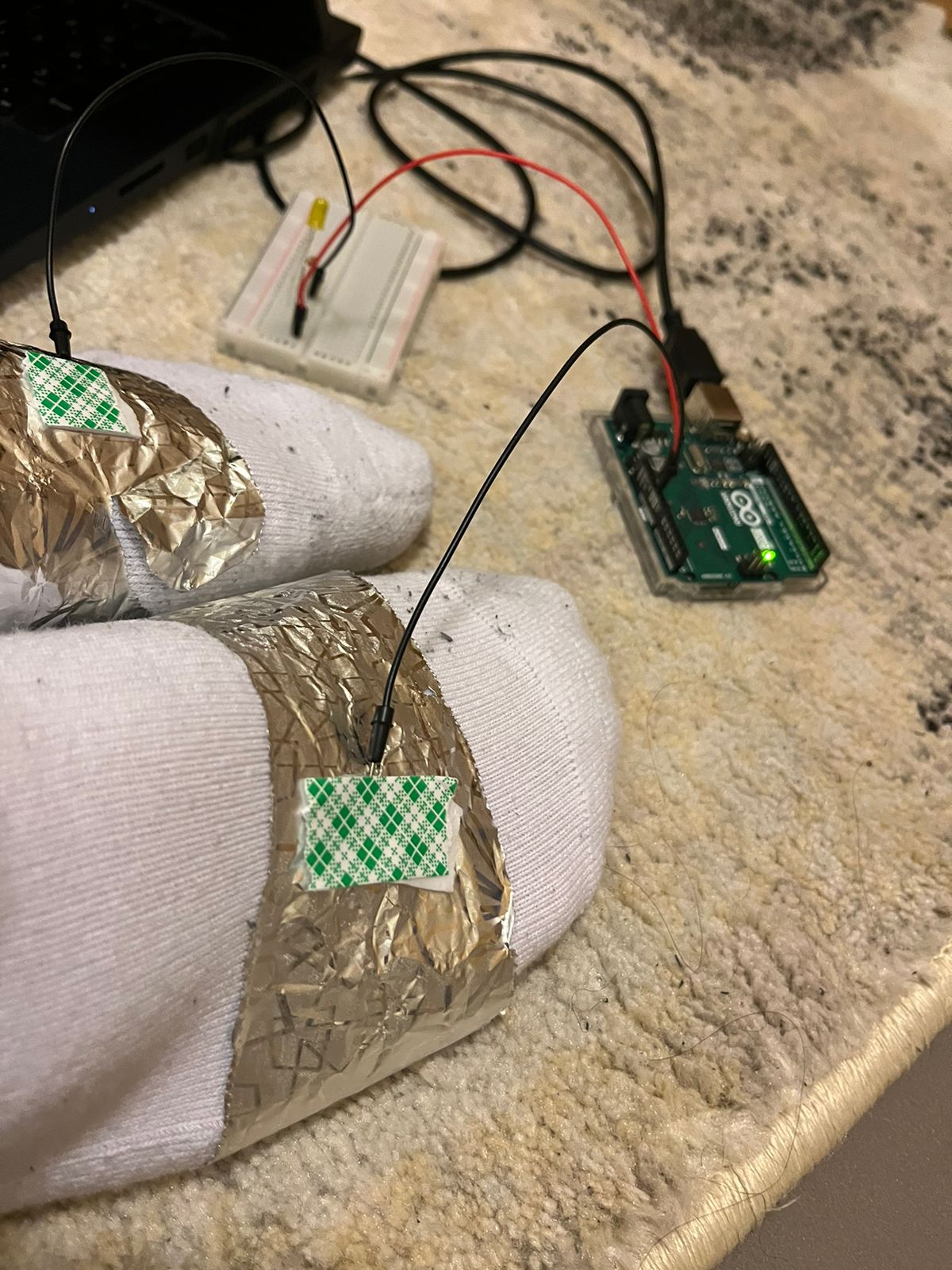
For this final project, I feel that I have learned a lot from the Arduino development field. Small things that we usually omit during the process of creating these types of projects become bigger problems when it comes to user usability and versatility. For example, the contacts for the glove are really hard to match due to the lesser amount of copper I had available. Moreover, the cables were extremely hard to position properly in order to fix them but also allow movement of the whole arm.

In general, the construction process for the cables and circuit was the hardest part of this project. I would like, in future iterations to improve the cable management and the outside box, maybe ideate some other way to construct a box that will allow the movement of the glove but also easy access if needed (open box).

To conclude, I have really enjoyed every step I took in this class. I have learned ways of expressing my ideas and thoughts in manners I would have never imagined. I have grown to love the idea of exploring new horizons and implementing new designs, approaches, methods for my projects.

Thank you and see you soon.

Week 12 – Final Project Idea Proposal, Design & Description

Concept Breakdown:

My idea for the final project will be an interactive glove: a innovative physical way of interacting with the computer. In this glove, we will be able to use certain hand gestures to send input to our Arduino and later on, our computer.  In order to comply with the hardware limitations and time restrictions, I will not utilize the glove as a mouse, as the use of a trackpad will require utilizing a board different than Arduino Uno (For example, the Arduino Micro, Pro Micro or Leonardo).

The Hand Gestures:

The hand gestures utilized will require touching the border of the palm (the other side if we check our knuckles) of our hand with a finger, regardless of which one we decide to use. Try it. Some people will be able to use it with one hand, some people will not. his means we will be able to use either the fingers in the same hand or the other hand. How does this work?

The user will use either one hand or both to control the input, which will be similar to a binary system: 0001. In this case, what we do is utilize the border right under every finger except for the thumb as one of the spaces for the input. This means that touching every part of the palm in different combinations will hold a different output (or input, from the Arduino’s point of view).

This leaves us with 2^4 different combinations that we can map to certain keyboard inputs because remember, a touchpad/mouse-style input requires a different board and honestly, many more inputs.

The Arduino Circuit and Design:

The circuit design is simple but effective. The idea will be to connect cables from the Arduino ports to the border of the palm. By connecting 5v current to all our fingertips, what we will be able to do is effectively create an array of switches that will trigger on our touch. We will attach all the necessary cables to the glove and cover the exterior to avoid disconnections and other problems.  Important to note that we will have to be aware of possible delays and misinputs, as it is a form of physical input.

Interactive Gloves : 8 Steps (with Pictures) - Instructables

The P5js sketch:

The P5js Sketch will be a way of demonstrating the inputs of the glove. We will utilize many of the previous projects we have done, such as the piano, the bouncing ball, the musical instrument and other little games in order to show the public that it is possible to control the input differently.

The Connection:

As much as the communication between p5js and Arduino should be obvious at this point, we will compute the inputs in the circuit before sending a single “key” input to p5js. This means that we have no delay in terms of the computation nor we will need to send more information than necessary. A great addition would be also for p5js to send a response to Arduino. For example, the piano could have its output coming from a speaker.

Week 11 – Final Project Ideas

Idea 1:

For my first (and main) idea, I want to work with the concept of IOT and Home Automation. In this case, as cliche as it might sound, I would like to have a central control unit for every interactive part of our houses. What this allows is to have direct control over every item in the house, which at the same time allows me to make the main part of this project, which is an assistant that will be able to act on every interactive item of the house. The multiple ways of connecting to it will allow a variety of options and ideas.

Idea 2:

For this project, the idea is to create a combination between 2 of the most popular game genres this year: rhythm games and combination games. The concept is to create a rhythm game that every time you get a perfect hit, a  ball will fall, which will allow the user to drop the balls in order to combine them and achieve a higher score.

Week 11 – Exercises

  1. Make something that uses only one sensor  on Arduino and makes the ellipse in p5 move on the horizontal axis, in the middle of the screen, and nothing on arduino is controlled by p5

    let rVal = 0;
    let alpha = 255;
    let left = 0;
    let right = 0;


    function setup() {
    createCanvas(640, 360);
    noFill();
    //create an ellipse with x position changing and y (300) position constant
    }
    
    
    function draw() {
    background(255);


    if (!serialActive) {
    fill(0)
    text("Press Space Bar to select Serial Port", 20, 30);
    } else {
    fill(0)
    text("Connected", 20, 30);
    }
    let xPos = 300;
    xPos = map(alpha, 0, 1023, 0,640);
    ellipse(xPos, 150, 50, 50);
    
    
    console.log(alpha);
    }
    
    
    function keyPressed() {
    if (key == " ") {
    // important to have in order to start the serial connection!!
    setUpSerial();
    }
    }


    For this question, we decided to create a simple ellipse that changes direction based on the values from the potentiometer.

  2. make something that controls the LED brightness from p5t
    function keyPressed() {
    if (key == " ") {
    // important to have in order to start the serial connection!!
    setUpSerial();
    }
    if (key== "1"){
    left = 50;
    }
    
    
    if (key== "2"){
    left = 100;
    }
    if (key== "3"){
    left = 255;
    }
    if (key =="4"){
    right = 50;
    }
    if (key =="5"){
    right = 100;
    }
    if (key =="6"){
    right =255;
    }
    }


    This one was pretty simple. Pressing the keys 1-6 increases/decreases the brightness of the left or right LED light. 1-3 correspond to the left, while 4-6 correspond to the right led.

  3. take the gravity wind example (https://editor.p5js.org/aaronsherwood/sketches/I7iQrNCul) and make it so every time the ball bounces one led lights up and then turns off, and you can control the wind from one analog sensor.
let rVal = 0;
let alpha = 255;
let left = 0;
let right = 0;
let velocity;
let gravity;
let position;
let acceleration;
let wind;
let drag = 0.99;
let mass = 20;


function setup() {
createCanvas(640, 360);
noFill();
position = createVector(width/2, 0);
velocity = createVector(0,0);
acceleration = createVector(0,0);
gravity = createVector(0, 0.1*mass);
wind = createVector(0,0);
}


function draw() {
background(255);
applyForce(wind);
applyForce(gravity);
velocity.add(acceleration);
velocity.mult(drag);
position.add(velocity);
acceleration.mult(0);
ellipse(position.x,position.y,mass,mass);
if (position.y > height-mass/2) {
velocity.y *= -0.9; // A little dampening when hitting the bottom
position.y = height-mass/2;


}
console.log(position.y);
if(position.y >= 330){
left = 1;
}
else if(position.y <= 330){
left = 0;
}
console.log(rVal);
wind.x = map(alpha, 0, 1023, -1, 1);


if (!serialActive) {
fill(0)
text("Press Space Bar to select Serial Port", 20, 30);
} else {
fill(0)
text("Connected", 20, 30);
}
}
function applyForce(force){
// Newton's 2nd law: F = M * A
// or A = F / M
let f = p5.Vector.div(force, mass);
acceleration.add(f);
}


function keyPressed() {
if (key == " ") {
// important to have in order to start the serial connection!!
setUpSerial();
}
if(key == "1"){
left = 1;
}


}


For changing the wind direction, we followed similar logic to the first question. The ball changes direction based on values mapped from the potentiometer.

Week 10 Reading Reflection

A Brief Rant on the Future of Interaction Design

From a personal point of view, I think that the main point of this text might be misunderstood by a lot of people. More than anything, because the follow-up article is a key part that adds context, depth, and information to the author’s rant.

In any case, I agree with a big part of the ideas presented in the text. However, it is not clear to me whether the problems presented should be taken with the same heaviness the author mentions. The reason behind this is none other than the feasibility of a solution to the problems that the author mentions. I believe the critique makes total sense because it gives value to the other mobility functions of the human body. However, finding new methods of interaction that the common user would prefer over traditional ones is not an easy task. If it helps, we never imagined leaving the mouse and keyboard behind, and here we are, using touch screens in everything. Considering how old this article is, it makes sense for the author to say that we should leave touchscreens behind eventually. But, after 10 years, we clearly haven’t moved on.

A follow-up article

As I mentioned before, the idea of a “rant” was confusing indeed. Most readers expect to find a solution to the problems presented in the previous text, but none were found. This is simply because most people will not get the main point of this text. The text does not imply that a solution will be found any time soon, but the opposite: the main objective is to inspire and motivate people to start researching for an answer.

I personally think he makes a great point in his ideas for the future. This doesn’t mean either I can provide a clear answer to the problems that he proposed back in his rant, but I can definitely say that reading his post encouraged me to start thinking about them.

Week 10 – Creative Musical Instrument

Concept:

For this week, Izah and I decided to create a musical instrument based on our favorite analog sensor: the photoresistor. To do this, we decided to utilize an interesting concept to make the instrument work: an instrument that can only be played with 2 people. The idea here was to provide a completely different experience compared to traditional musical instruments. First of all, by allowing the notes only to be played with 3 hands and second, allowing to have different notes based purely on the placement of the hand (no touch). Because no traditional instrument requires 2 people to play it, we considered that this would be a greatly innovative idea.

Demonstration


Code highlight:

if (switchState ==1){
    //sensor 1
    if(sensorValue1 > 500){
      currentState+=100;
    }
    else if (sensorValue1>250 && sensorValue1 < 500) {
      currentState+=10;
    }

    else if (sensorValue1 < 250){
      currentState+=1;
    }

    //sensor 2
    if(sensorValue2 > 500){
      currentState+=100;

    }
    else if (sensorValue2>250 && sensorValue2 < 500) {
      currentState+=10;

    }

    else if (sensorValue2 < 250){
      currentState+=1;
    }

    //sensor 3
    if(sensorValue3 > 500){
      currentState+=100;

    }
    else if (sensorValue3>250 && sensorValue3 < 500) {
      currentState+=10;
    }

    else if (sensorValue3 < 250){
      currentState+=1;
    }

This code provides the change of currentState. Current State can be incremented in increments of 1, 10, or 100. This ensures that the state is always controlled in a way where we can always tell exactly in what level all sensors are working on. For example, if currentState = 111, then that means that there is one HIGH, one MID and one LOW state, regardless of which is which.

Challenges:

In this project, we faced multiple challenges that slowed down and hindered our development. For starters, because of the circuit that we built, being able to sustain the structure of the instrument was a big challenge we had to face. To solve this problem, we utilized a cardboard base, supported by the same paper cups we used to cover the light for the photoresistors.

Improvements:

In this case, the improvements would be related to polishing the implementation of the photoresistor detection. One of the biggest improvements we could apply would be to place all sensors at the same angle, in such a way that all of them captured the same light level initially. By doing this, the hand movements could be more streamlined and straightforward. Because we  utilized

Another possible improvement would be to solder the photoresistors and the cables together in order to provide a more solid connection and avoid some connection problems that happen every once in a while.

Week 9: Cookie Jar

Concept:

For this week, our task was to get information from at least one analog sensor and at least one digital sensor (switch), and use this information to control at least two LEDs, one in a digital fashion and the other in an analog fashion, in some creative way.
My project is called “The Cookie Jar”, and it’s inspired by my love for chocolate chip cookies.

After recklessly spending my savings on this bucket of cookies, I decided to base my project on it. The idea was to turn a light on every time I opened the lid of this cookie bucket. To do this, I had to code the photoresistor in a way that it could take the difference between the light outside and the light inside. However, the problem relied on the fact that turning on the LED also generated light by itself, so I had to adapt the constraints of it in a way that would work properly. Also, I added a switch to turn on and off manually the other light inside, just in case someone wants to sneak a cookie in the middle of the night.

Breadboard and connections: 

Demonstration:


Code: 

void setup() {
  // put your setup code here, to run once:
  Serial.begin(9600);
  pinMode(5,OUTPUT);
  pinMode(9,OUTPUT);
  pinMode(2,INPUT);
  pinMode(A2,INPUT);
}

bool lightsOn = false;
void loop() {
  // put your main code here, to run repeatedly:
  int sensorValue = analogRead(A2);
  int switchValue = digitalRead(2);
  
  if(switchValue == 1){
    lightsOn = !lightsOn;
    delay(500);
  }
  digitalWrite(9,lightsOn);
// The brightness is the difference between inside and outside, but reversed (more light if the difference is low)
  int brightness = 255-(620-sensorValue);
  if(brightness<0){
    brightness = 0;
  }
  if(brightness>255){
    brightness = 255;
  }
  analogWrite(5,brightness);
  Serial.println(sensorValue);
  
}

Challenges:

The biggest challenge I faced was the shape and the fact that I had to connect the arduino UNO inside with the lid closed. I fixed this problem by reluctantly making a hole in my cookie bucket. I opened it just enough so it could fit the USB connector, which allowed me to insert the circuit inside even with the lid closed.


Week 9 – Reading Reflection

Making Interactive Art: Set the Stage, Then Shut Up and Listen

In this blog post, Tom Igoe talks about shifting the focus on what interactive art should be: instead of a complete piece, a finished artwork, we should approach it as if they were “performances”. His ideas, in my opinion, provide a valuable lesson on the final objective of interactive pieces. Every person might have their own vision and goals for their projects and art pieces, but at least for me, ultimately what I would like to achieve is to create something that people can see and be satisfied with their experience. I do not want to have to be present, or to have to talk to people explaining what they have to do in order to have the experience. In my opinion, that is the essence of interactivity and one of the key components of good design: the user should start, process and finish the experience by themselves.

Physical Computing’s Greatest Hits (and misses)

In this article, Tom Igoe discusses recurring themes in physical computing projects, highlighting popular ideas and their variations. In my opinion, I think that from this article, the author encourages creativity within these themes (physical computing recurring themes), emphasizing that even though certain ideas have been done before, there is room for originality and variation. And I personally want to emphasize this last part. “I don’t want do to that, it’s already done”, this quote resonated especially hard in my head. The reason behind this dates back to my highschool, where during a rough patch in my software development learning process, I struggled to think about projects that could be usable but would also help me learn. In my head, I was constantly repeating these exact words that the author included: “it has been done before, why care?”.

This mindset was what stopped me from improving as a creator and as a programmer. The principal of my highschool came up to me one day, and he clearly told me one example: “I do not want you to invent the wheel, and I do not want you to invent the suitcase. I want you to explore, and maybe you will end up creating the travel luggage”.

This article helped me remember those learnings, and I think the moral of the story is also one of the pillars of creativity: be able to push away your ego and work with things that are created, work on stuff that has been invented and do not shy away from these opportunities, because Rome was not built in one day, and definitely not from scratch.

Week 8 Reading Reflection

Attractive Things Work Better by Donald A. Norman

This preview of Norman’s book “Emotion and Design” discusses the relationship between aesthetics and usability in design, starting with the example of teapots. While some critics argue that adhering to usability alone can result in ugly designs, the author suggests that beauty and usability should not be in conflict, as he describes in his phrase: “pleasurable designs are not necessarily usable”. However, from my point of view, the key point behind his idea is the fact that he relates cognitive studies that explore the concept of affect or emotional reactions in design. Affect has a significant impact on how people perceive and interact with products. In stressful situations, negative affect can lead to “tunnel vision”, while in positive or neutral situations, positive affect can promote “breadth-first thinking” and creativity, making users more tolerant of minor design issues and distractions. The author emphasizes that true beauty in a product should go beyond aesthetics and should be rooted in usability and functionality, and that design should combine and include various factors like marketing and aesthetics, and in my opinion, this is the most important learning we should take from this text.

Her Code Got Humans on the Moon – Robert McMillan

More than just an “outlier”, Hamilton was a pioneer in her field. Not even a pioneer, she was the founding pillar of modern software and the importance of it. The inhuman pressure that was born from the Apollo mission and its dependence on the software Hamilton was producing is, without doubt, one of the main reasons why companies, CEOs, and global leaders all around the world started to put their eyes (and resources) on software development. As she describes, “the original document laying out the engineering requirements of the Apollo mission didn’t even mention the word software”.

For me, it’s impressive how the software for this was produced at that time. Especially considering that the Apollo mission was a life or death matter for the astronauts, and definitely the most ambitious human project ever made at that time. The process in which Hamilton and the “Little Old Ladies” engraved the commands that made the Apollo mission such a famous and ultimately successful project was almost superhuman, and definitely an example for all aspiring software developers around the world. The story behind program PO1 and the “fool-proof” coding style that Hamilton proposed and was initially rejected is without a doubt a fundamental concept in today’s software development: secure, safe, and error-avoiding code.

Week 8 – Getting creative with switches

Concept:

The idea behind this switch was to utilize something different than just our hands to control it. For this project, I decided to focus on one of the human body parts that we rarely include in our interactive projects: the feet.

To control this switch, the user will put together both feet in order to make a bridge between the two cables attached to the socks on each side. Something similar to how a pedal works. This switch would allow the user to use limbs that we usually do not include in our movements that intend interaction with a system: For example, a phone doesn’t need our feet, a camera doesn’t need our feet, and even computers usually don’t require our feet to be there.

Foot Pedal Switch, USB Foot Switch for Computer, Motion Switch, Mouse,  Keyboard, Game, String and Multimedia, Programmable on Any Windows PC: Buy  Online at Best Price in UAE - Amazon.ae

Demonstration:


Challenges and improvements:

At first, I tried taping the tin foil to the socks. Surprisingly, because of how our feet are shaped, taping the cables was a tougher task than I expected because they would move and disconnect the moment I wore the socks. In addition to that, the tin foil is not exactly a strong material, which meant that the contact was interrupted sometimes. This was simply fixed by the most utilized solution in human history: just fix it with more tape, both in the cables and the tin foil surrounding the socks. Also, I taped the cables and the tinfoil after I wore the socks, which solved the foot shape problem.