Final Project: Don’t Strangle Daisy!!

Concept:

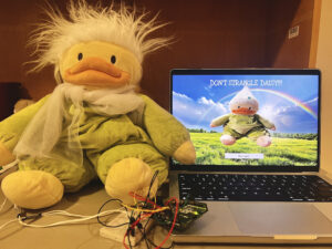
For my final project, the idea switched from a wholesome cuddly teddy bear that gets happier the tighter you hug it, to a tragic ending for Daisy the duck, where she gets sadder the harder users strangle her up until the point where she dies. My intention was to create a wholesome stress reliever for finals season, but it ended up still working in that many users found it to be stress relieving, but it was in a very aggressive manner. This was due to the struggle to find a proper spot for the flex sensors to sit inside of her, so I found it easier to put it around her neck. Depending on the amount of pressure the user puts onto Daisy as they strangle her, her emotions get more and more depressing the stronger the pressure is, which is shown through the p5 display.

Picture:

Implementation:

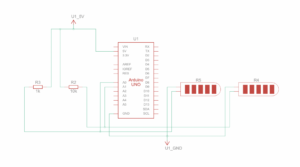
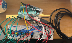
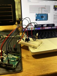
The physical aspect was relatively simple before I had to figure out how to attach the flex sensors onto Daisy. I connected two flex sensors to the Arduino board, and with the help of several male-to-male and female-to-female jumper wires, I was able to lengthen the “legs” of the flex sensors from the bread board, which allowed for more flexibility when working with the placement of the flex sensors. The difficult part was figuring out how to neatly link the flex sensors to Daisy.

The initial idea was to cut her back open and place the sensors and possibly the breadboard and Arduino inside of her, and then sew her shut. This ended up being problematic because from test hugs, a lot of people hugged her in different ways. Some hugged her with pressure on her stomach while some hugged her with pressure on her head. This would’ve caused issues with the project functioning or not, because that depends on whether users accurately apply force on the flex sensors. Additionally, I had some concerns over the wires getting loose and detached while inside of Daisy. It would’ve also made her really heavy with a thick inconvenient cable coming out of her back, which is the one that connects the Arduino board to my laptop.

I ended up revamping the idea into placing the flex sensors around her neck. Not only was this much easier to implement as I just used some strong double sided stick tape, it was also a lot easier for people to understand what to do without having to give precise detailed instructions on where to hold her. The double sided stick tape was a lot stronger than expected, and still held up after the showcase, although I’m not so sure how well the flex sensors work now. I think they’ve become a little desensitized to all the pressure.

To cover the flex sensors to make it look more neat, I initially made a paper bow to attach to her, but after looking around the IM Lab, I found a small piece of mesh fabric that made a perfect scarf for her, which covered the flex sensors really naturally.

As for the P5 side of things, I took a lot from what I learned while making my midterm project, where I layered different pictures together. These layered backgrounds and pictures of Daisy would represent and visualize her mood, as each layer would show only if the pressure received from Arduino was between a certain amount. For example, if the pressure average was greater than 965, p5 would layer and display Daisy in a happy mood alongside a sunny rainbow background. She has 4 moods/stages. Happy, neutral, sad, and dead. These stages also have corresponding music that plays when the level is unlocked. The p5 also has a mood bar that matches the intensity of the pressure and also changes color to match the mood it reaches. The Arduino code calculated the average of the two flex sensors, so the p5 would display different images depending on the pressure number.

Arduino Code:

Final Project Arduino Code

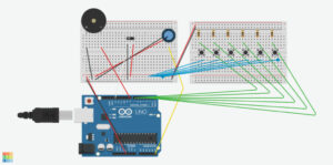
Schematic:

Challenges and Proud of:

I struggled a lot with, as mentioned earlier, the placement of the flex sensors. I really wanted to keep the wholesome concept of the initial idea I had, so I really had to brainstorm ways to execute it, but I ended up changing it. I found it to be for the better, as the idea seemed to grab people’s attention a lot more than I expected. It was really popular at the IM Showcase and everyone wanted to strangle poor Daisy, up to the point where the flex sensor pressure wouldn’t go lower than roughly 650, which meant it was really difficult for people to reach her “Sad” stage and even harder to kill her. I ended up tweaking the numbers a bit during the showcase so people could feel satisfied with reaching her “Dead” stage, but it wasn’t that way at the start of the showcase.

I was really proud of this project overall and I was satisfied with the way it turned out even though it was a complete 180 from my idea. It did relieve a lot of people’s stress, just not in the way I intended or expected it to be. It was really funny to watch everyone strangle this poor plushy just to reach the “Dead” stage, and to see the pure joy on people’s faces once they managed to kill her. I was also proud that I properly managed to add that “Dead” stage and also complementary music a bit before the showcase.

Future Improvement:

In the future, I would want to figure out how to prevent the flex sensors from “wearing out” so that it wouldn’t affect the sensitivity of it. I would also want to add more flex sensors so that people could strangle Daisy however they want without having to stay on one specific line in order for it to work from there being more surface area to work with.

Showcase:
IM Showcase Interaction

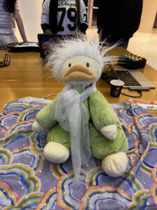
The tragic aftermath of Daisy by the end of the IM Showcase. Very stiff.


Final Project User Testing

User Testing

For the user testing, I think the fact that the same plushy in real life was on the p5 screen kind of hinted at what users were supposed to do, especially since the sensors were not so subtly taped onto the back of the plushy. The physical aspect of the project is still in the makes, which is why the sensors were on the back, because I’m still trying to figure out the best way to implement the sensors without taking away from the capabilities of the flex sensors. Ideally, I wanted to stuff the flex sensors as well as the arduino board and bread board into the plushy, but I realized how heavy it would be and also the struggle of the jumper wires potentially disconnecting. I think that if I stuck with the plan where the only thing visible was the arduino cable to connect to my laptop, it would be less self-explanatory and a bit harder to figure out since the sensors wouldn’t be in plain sight.

I think there was some confusion on how exactly the plushy should be squeezed. I don’t think the user knew it was supposed to just be hugs, but he probably hugged the plushy simply because it’s a cozy plushy. If it were a different object, I don’t think his first instinct to interact with it would be to hug it. He ended up squishing the plushy between his palms as well, which was a really interesting way of playing with it.

I think the overall concept is working well, where the pressure value and p5 connection is working properly, but there could be major improvements in where the sensors/arduino components could be within the plushy, as well as better p5 display and design with instructions and maybe some context on the project. I think I would have to explain the purpose of it because knowing your tight hugs make the plushy’s day would definitely add more positivity into the interactive experience. I would also have to explain how exactly it would work, which is a bit complicating because saying to just hug it is a bit vague since I only have two flex sensors, so if they hug an area without the sensor, the p5 screen wouldn’t reflect anything, which would be a pretty disappointing outcome. Having just brief words on the p5 screen before or maybe during its start would help make sense of the idea

Final Project Progress

Finalized Concept:

For my final project, I decided to stick with the idea of a plushy that can react to your hugs. Designed to spread positivity and happiness for everyone especially during finals season, I want the P5 to output the plushy’s “mood scale” based on the tightness (pressure) of the hug.

The repeated idea:

Sometimes, all we need is a long hug to help us recover from a long day. So, why not be able to hug a responsive cute fuzzy plushy?

Although it doesn’t have a name yet, this plushy with a pressure sensor will be able to activate various designs on the P5 screen when the user hugs it. Ideally it will output randomized sounds for each hug, such as “That made my day!” “Aww thanks!” “Cozy!” Etc.. no matter the tightness of the hug. I will also try to create a digitally animated version of it, where it can have 4 different facial expressions as well as 4 different mood settings and backgrounds. These will range from a little sad to very happy. In the end, I just want to create something that will make users feel loved and appreciated, even if it’s just from a little plushy

D&D of Arduino:

For the design of the Arduino, the project’s physical aspects consist of the plushy being able to detect the user’s inputs so that it can send an output through its speaker and P5. Using either a pressure sensor or a flex sensor, depending on which one better suits the plushy, it will be placed inside of the plushy so it can take in the hug and measure the intensity of the hug. This hug intensity data will be sent to Arduino, which will output randomized sound effects through the piezo buzzer. The pressure data will also be sent to P5.js through the “handshake” of serial communication between Arduino and P5.js, which will be how all of the digital magic appears.

D&D of P5:

As for the P5 side of things, the P5’s input would be the received pressure data from Arduino. There will be 3 different levels of pressure values that the data can reach, which will be mapped to different outputs depending on which of the three pressure levels that user’s hug reaches. This would then output the digital plushy’s various expressions and backgrounds. The P5 screen would output the visuals to match the intensity of the user’s hug, and I’m hoping I’ll be able to make the differences pretty drastic so the user can get the idea that a tighter hug will output different visual feedback

Final Project Idea

Sometimes, all we need is a long hug to help us recover from a long day. So, why not be able to hug a responsive cute fuzzy teddy bear?

The idea for my final project is still pretty rough, but I want to make something that is cute and wholesome that can also help promote well-being as final season is approaching. I was thinking of a teddy bear with a pressure sensor that activates LEDs that form a heart shape when the user hugs it. Maybe I could also figure out getting it to output randomized sounds for each hug, such as “That made my day!” “Aww thanks!” “Cozy!” Etc.. The P5 screen could animate a corresponding background for the teddy bear in awe, such as a bunch of hearts growing in size or cheerful floating bubbles. In the end, I just want to create something that will make users feel loved and appreciated, even if it’s just a little teddy bear

For a back up idea, that’s actually quite ambitious, I thought I could make a fake robot pet that’s always grumpy and will turn around and move away from you when you come close to it unless you have a hot treat for it. I think think the hot treat part might be a bit hard to accomplish, because warm cookies aren’t super hot and I haven’t used a temperature sensor yet, so I don’t know how sensitive it is

Reading Reflection – Week 11

In this exploration between design and disability, the author shows how design can evolve beyond simply addressing a disability and instead serve as a powerful tool for self-expression and even empowerment. Glasses were once purely a medical device, and now, they have become a fashion accessory, where people who don’t even need glasses to fix their vision will still want a pair for the looks of it. This shift in design can go from solely functionality to embracing style and personal expression, and the glasses example was pretty predictable, but the example on Hugh Herr’s prosthetic limbs in particular really stood out! I liked that he used his prosthetics as a form of empowerment towards him as a rock climber by having telescopic legs that could extended to different lengths while climbing, which would give him an advantage.

I think the topic of accessibility is one that can never be spoken about enough, as there’s always something that ends up being inaccessible because it wasn’t clear if accessibility was kept in mind while creating those designs. We have to keep in mind that not all disabilities are the same and not all disabilities are visible. With how much we’re advancing today and continuing to advance each day, we can learn more on how to move beyond the traditional medical models and instead figure out how to enhance and celebrate the body as well as the technology and artistry of the medical device.


Exercise 1:

Make something that uses only one sensor on Arduino and makes the ellipse in p5 move on the horizontal axis, in the middle of the screen, and nothing on Arduino is controlled by p5.

The location of the x of ellipse is being altered by the potentiometer.

The value from the potentiometer is mapped between 0 and 640, the width of the canvas.

Utilizing a Potentiometer, the ellipse moves along the horizontal axis, while also changing colors by making changes to the B value of fill.

Arduino Code: 

P5 Code:

let ellipseX = 0; //x value of ellipse to be changed by potentiometer
let B =0;

function setup() {
  createCanvas(640, 480);
  ellipseMode(CENTER);
}

function draw() {
  clear();
  background(0)
  fill(255,0,B);
  ellipse(ellipseX, height/2, 50, 50);


  if (!serialActive) {
    text("Press Space Bar to select Serial Port", 20, 30);
  } else {
    text("Connected", 20, 30);  
    // Print the current values
    text('ellipseX = ' + str(ellipseX), 20, 50);
  }
}

function keyPressed() {
  if (key == " ") {
   
    setUpSerial(); //establish serial communication
  }
}

function readSerial(data) {  
  if (data) {    //run only if data is received
    data = data.trim(); // Remove any whitespace
    if (!isNaN(data)) { //check whether data is a number or not
      //debug: console.log("Received:", data);
      ellipseX = int(data);
    }
  }

Exercise 2:

Make something that controls the LED brightness from p5.

A slider is created and data from it is sent to the Arduino. Based on the input from the p5 sketch, the LED’s brightness is adjusted accordingly.

Arduino Code: 

P5 Code:

let slider;
let brightness = 0;
function setup() {
  createCanvas(400, 400);
  // Create a brightness slider
  slider = createSlider(0, 255, 128);
  slider.position(width/2, height/2);
  slider.style('width', '100px');
}
function draw() {
  background(255);
  if (!serialActive) {
    textAlign(CENTER)
    text("Press Space Bar to select Serial Port", width/2, height/3);
  } else {
    text("Connected", width/2, height/3);
  }
  brightness = slider.value();
}
function keyPressed() {
  if (key == " ") {
    // important to have in order to start the serial connection!!
    setUpSerial();
  }
}
function readSerial(data) {
  console.log(data);
    let dataToSend = brightness + ", \n";
    writeSerial(dataToSend);  
}

Exercise 3:

Take the gravity wind example and make it so every time the ball bounces one led lights up and then turns off, and you can control the wind from one analog sensor.

Using a potentiometer mapped from -2 to 2, when the potentiometer is towards the left, the wind blows towards the left, and vice versa. The LED lights up every time the ball touches the bottom edge of the canvas.

A serial signal is sent to arduino everytime the ball touches the bottom of the canvas, resulting in the led to light up on the arduino. The potentiometer’s value will be reflected in the direction that the wind is blowing on the ball. I also added two walls on the right and left sides of the canvas, to prevent the wind from blowing the ball outside of the canvas.

Arduino Code:

P5 Code:

let led;
let velocity;
let gravity;
let position;
let acceleration;
let wind;
let drag = 0.99;
let mass = 50;

function setup() {
  createCanvas(640, 360);
  noFill();
  position = createVector(width/2, 0);
  velocity = createVector(0,0);
  acceleration = createVector(0,0);
  gravity = createVector(0, 0.5*mass);
  wind = createVector(0,0);
}

function draw() {
  background(255);
  applyForce(wind);
  applyForce(gravity);
  velocity.add(acceleration);
  velocity.mult(drag);
  position.add(velocity);
  acceleration.mult(0);
  ellipse(position.x,position.y,mass,mass);
  if (position.y > height-mass/2) {
      velocity.y *= -0.9;  // A little dampening when hitting the bottom
      position.y = height-mass/2;
    
    
    if(serialActive){
      writeSerial("bounced\n");
    }
    }
  // Check for collisions with the left wall
  if (position.x < mass / 2) {
    velocity.x =0; // Reverse horizontal velocity (bounce)
    position.x = mass / 2; // Correct position
  }

  // Check for collisions with the right wall
  if (position.x > width - mass / 2) {
    velocity.x =0; // Reverse horizontal velocity (bounce)
    position.x = width - mass / 2; // Correct position
  }
}

function applyForce(force){
  // Newton's 2nd law: F = M * A
  // or A = F / M
  let f = p5.Vector.div(force, mass);
  acceleration.add(f);
}


function keyPressed() {
  if (key == " ") {
    // important to have in order to start the serial connection!!
    setUpSerial();
  }
  if (keyCode==DOWN_ARROW){
    //mass=random(15,80);
    position.y=-mass;
    velocity.mult(0);
  }
}


function readSerial(data){
  
  if (data != null){
    wind.x=int(data);
    console.log("working");

  }
}


Reading Reflection – Week 10

A Brief Rant on the Future of Interaction Design:

This was a really nice read! I enjoyed this new rant-style writing that was also very visually telling of what the author was ranting about. I definitely agreed with his point at the start, and that only solidified more and more as I read all of the examples he pointed out, where everyday activities seem so simple, yet are actually complex, but we just do it out of instinct.

The fact that we have different types of fundamental grips for different purposes is so interesting! It really put hand manipulation into perspective because there’s only so many options you can do with a touch screen, and all of them are the same sliding or tapping on a glassy screen.

Another really interesting point he made was how we often think vision carries us a lot, but that’s because we’re not consciously thinking about the significance of touch. This example in particular really stood out to me and made me think twice about how important it is for our hands to feel things and understand weight and texture as well.

Try this: close your eyes and tie your shoelaces. No problem at all, right? Now, how well do you think you could tie your shoes if your arm was asleep? Or even if your fingers were numb? When working with our hands, touch does the driving, and vision helps out from the back seat.

Although I do agree that “pictures under glass” technology limits our physical interaction and connection with the devices, as well as the power and capabilities of our hands, I think it’s still crucial to consider how easy and accessible digital devices can make things. Yes, we wouldn’t be able to tell how far into a book we are if it’s digital instead of physical, but it could save the burden of carrying 4 thick textbooks with you throughout the school day, or make it easier for people to access international books that aren’t physically sold in their country. There are pros and cons to either side of things, and it would be revolutionary if we could find a way to somehow combine human capabilities and glassy technology by making it multi-sensory.

Responses on the Rant:

Reading people’s responses to the author’s rant as well as the author’s responses to those readers’ responses was quite fascinating and the way he explained and defended himself was nicely straight to the point. I enjoyed how he was kind of sarcastic in the initial response and then followed up with some true examples to further defend his case, such as:

Yeah! iPhone bad! iPad bad!

No! iPad good! For now! In 1900, Eastman’s new Kodak camera was good! The film was black-and-white, but everyone loved it anyway. It was genuinely revolutionary! But it was also obvious that something was missing, and research continued. Practical color film was released thirty years later, and gradually took over.

Assignment 10: Musical Instrument – Piano

Concept:

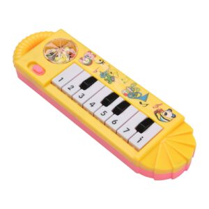
For this assignment, we were inspired by the toy pianos that we’ve all played with at least a few times as children. These toys were often quite limited, as they only had enough space to accommodate the keys for a single octave. We decided to create a miniature piano that could play the notes from C to A, with a knob that can be turned to change octaves.

Toy Piano

Setup and Code:

We set up a row of buttons that play a note when pressed, a potentiometer that changes the octave, and a switch that switches the notes to their respective sharp notes.

We created arrays that store the frequencies of the natural notes across seven octaves, doing the same for the sharp notes. The range of the potentiometer is mapped to a range of 0-6 and determines which octave the notes will be played in. When the switch is low, natural notes are played, and vice versa.

To prevent the notes from continuously playing, the noTone() function stops the buzzer playing any sound when no button is pressed.

Github Code

if (buttonState7 == LOW && buttonState6 == LOW && buttonState5 == LOW && 
    buttonState4 == LOW && buttonState3 == LOW && buttonState2 == LOW) {
  noTone(8);  // Stop any tone on pin 8
}


Demo:


Reflection:

Overall, this group project was a success as we managed to recreate our inspiration using Arduino. We were really satisfied with how we made sure to implement the natural notes as well as sharp notes in our project. A few struggles we faced was that the wires and resistors were really crowded on our small breadboards, making it a little difficult to reach the buttons. Ideally, we would want to get bigger breadboards in the future so that there would be more room for interacting with the product. Additionally, the bread board was just a little too small for us to add the 7th natural note, so we could only fit 6, as we’re missing a B note.

In the future, we would like to add two different colored led lights that switch on and off along with the natural or sharp notes. This way, it would help users know if they are currently playing natural or sharp notes, as not everyone is familiar with musical notes in that sense.

Assignment 9: Rate Your Mood

Concept & Inspiration:

For this week’s project, we had to find a way to use both an analog and digital method to turn on a led light. I decided to use a button for my digital sensor, and a potentiometer for my analog sensor. My original idea was to use the button to change the colors of the two RBG led lights to represent different emotions and the potentiometer to change how dim or bright that emotion is for the day. For example, yellow being happiness, red being anger, blue being gloomy, purple as spirituality, etc. I tried to follow some tutorials, but it ended up being a bit too complicated, so I stuck to what we knew.

To rate your mood, users can twist the potentiometer to match how good they’re feeling, with the maximum blinking light representing them having a fantastic day. The button is a “feel good button,” meant to help users reduce their stress by fidgeting with a button that turns on with each click. The satisfying sounds may be soothing to some.

Demo Video:

Rate Your Mood

Github Link:

Rate Your Mood .ino File

Highlight Code:

if(buttonState == HIGH){
  digitalWrite(13,HIGH);
} else {
  digitalWrite(13,LOW);
}

The code I used is basically the exact same as the one we worked on in class while learning about digital input/output, except I made it so that the light was originally off and would turn on if the circuit is complete. Meanwhile in class, it was originally on and would turn off if the circuit was complete. This is highlighted because the feel good button is more satisfying when each click turns on the light, rather than turns off the light

Reflection + Future Improvements:

Overall, I’m still satisfied with how this project turned out. I got to use a new item (the RBG led light) and even though I didn’t get to use it the way I wished and planned for, I still got to use it for its automatic blinking that starts when the potentiometer is maximized. I didn’t do any of that with code, which was really cool. In the future, I would really like to expand on and execute the initial idea I had, to make the colors change with the button. In that case, I would also like to find a different way to create a “feel good button” or some other kind of satisfying fidget since the button would have a different purpose

Reading Reflection – Week 9

Physical Computing’s Greatest Hits (and misses):

Copying and originality are quite controversial topics when it comes to art, especially AI art. We tend to try to come up with fully new concepts, as some of our ideas might sound a bit too similar to preexisting concepts. This article talks about how it’s okay if your idea isn’t original, because there’s opportunities for you to make it so. The repetitiveness of certain project themes in physical computing can help users, especially those new to physical computing, learn to create variations of works that inspire them. It is a great means to study and learn concepts that are foreign to you, as you can recreate the work and later build onto it and make it more your own.

I like how the author encourages people to keep going through with an idea even though they think it’s not original. As someone who is still a beginner at physical computing, recreating unoriginal work is a great way to gain experience at the methods, while not needing the brain power to come up with something new when I don’t even understand the basics. The list will come in handy to me as gloves, video mirrors, and things you yell at are in my interest. I like how he also mentions the potential drawbacks of a few of the themes, and explains a situations where that could occur.

Making Interactive Art: Set the Stage, Then Shut Up and Listen:

I liked how almost brutal and straight to the point the author is about the concept of only being able to guide the audience through your interactive work and then shutting up and letting them work their way around your piece on their own. He makes a lot of good points about having to let the audience/users think for themselves when it comes to interpreting interactive art, and the acting example was a wonderful way of putting that necessary autonomy into perspective.

“You can suggest intentions, but you can’t give him interpretations. You can give him props to work with, or place them in the way so he’ll discover them. You can suggest actions, but you can’t tell him how to feel about those actions; he will have to find it for himself.”

It actually reminded me of a recent interaction I had with a friend who needed feedback on his Sound Project. It’s a project solely focusing on audio, with no visuals, and I got a bit lost by the middle and he had to explain what was happening for me to get it. Reading this piece reminded me of that because my interpretation of it wasn’t exactly how he wanted it to be, but he couldn’t just force those ideas into my head. Even after his explanation, I still couldn’t hear what he was pointing out, so my interpretation of his project would’ve been great feedback for him, since it would allow him to see from a perspective where he isn’t interpreting his own work. He can work on “setting the stage more” now that he has “shut up and listened.”