Week 13: Final Project

Crack the Code!

In this project, I’ve developed a “Crack the Code” puzzle to unlock a wooden box. The user receives four sets of hints to guess the three-digit code required to open the safe. Using the knob and button on the box, the user inputs each digit of the code. When the correct code is entered, the box unlocks, and the user wins the chocolate candies inside! Until the correct code is guessed, the box remains locked.

Video Demonstration of the Project

Interaction Design: The user is initially provided instructions on how to interact with the box through the computer screen. The red button on the box not only enters digits but also serves as a “start” and “restart” button for the game, functioning as a navigation button.


Beginning of the game. Box is locked and instruction to start is given on the screen.
Playing the game. Entering the digits of the code.
End of the game. Box is open and the candies are inside!!!

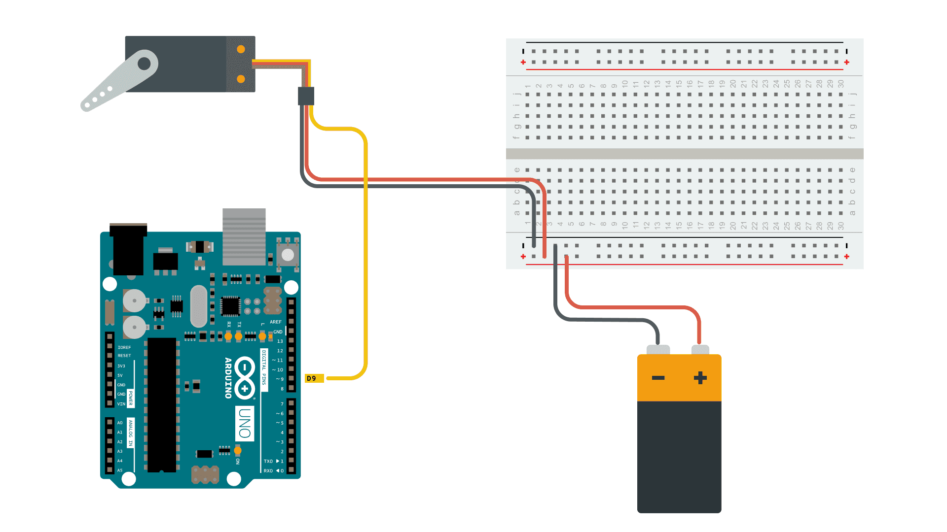
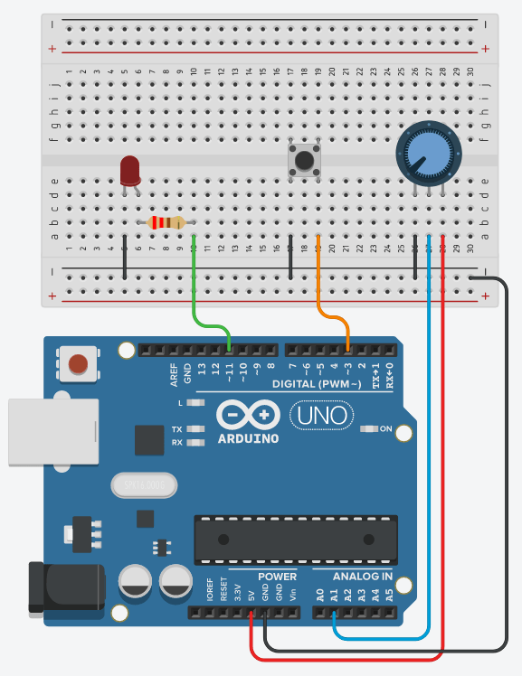
Arduino Sketch: My implementation involves using a servo motor, potentiometer, and button. The servo motor locks and unlocks the box by turning to 90 degrees when locked and 0 degrees when unlocked. The potentiometer changes the digits when the user inputs the code, mapping different resistances to digits from 0 to 10 (mapped to 0-9 initially, but because of display issues, extended to 10). The button navigates the game or inputs digits based on the game state. These data are sent to p5.js, which in turn determines whether to open the box or not.

const int servoPin = 9;
const int buttonPin = 3;
const int potentioPin = A1;
const int ledPin = 11;

#include <Servo.h>
Servo myservo;

int potValue;
bool locked = true;
int digit;

void setup() {
  pinMode(ledPin, OUTPUT);
  digitalWrite(ledPin, HIGH);
  delay(1000);
  digitalWrite(ledPin, LOW);

  myservo.attach(servoPin);
  pinMode(buttonPin, INPUT_PULLUP); 

  Serial.begin(9600);

  // Always lock the safe at the beginning of the program
  unlock();
  delay(2000);
  lock();
}

void loop() {
  // Check if data is available to read from serial
  if (Serial.available() > 0) {
    // Read the incoming data
    String receivedData = Serial.readStringUntil('\n');
    
    // Print received data to the Serial Monitor
    Serial.println(receivedData);
    
    // Check if the received data matches 'true' (to unlock)
    if (receivedData == "true") {
      unlock(); // Unlock the safe
    } else if (receivedData == "false") {
       lock(); // Unlock the safe
    }
  }

  int buttonState = digitalRead(buttonPin);
  potValue = analogRead(potentioPin);
  digit = map(potValue, 0, 1023, 0, 10);

  // Print values to Serial Monitor in a single line
  Serial.print(digit);
  Serial.print(", ");
  Serial.print(buttonState == LOW ? "false" : "true"); // Check if button is pressed
  Serial.print(", ");
  Serial.println(locked ? "true" : "false");
}

void lock() {
  myservo.write(0); // Set the servo to lock the safe (position 0)
  locked = true; // Update the locked status
}

void unlock() {
  myservo.write(90); // Set the servo to unlock the safe (position 90)
  locked = false; // Update the locked status
}

P5.js Sketch: The primary instructions and hints are presented to the user in the p5 sketch. There are three different code sets, one of which is chosen as the code to open the box at the game’s start. I was initially planning to code different sets of hints and it was a difficult process, I changed it to three sets of codes for each game round. For wrong inputs, there’s sound and visual feedback. I aimed for fun and engaging screen slides, including real box images for clear user instructions.

The p5 sketch receives data from the Arduino potentiometer to display corresponding digits. When the game state ends, it sends a signal to Arduino to open the box, and the servo motor complies.


In this project, I’m particularly proud of the box I’ve created. Despite the door hinges don’t function perfectly as intended, the box maintains a good overall shape. The box is made out of ply wood. Creating the box involved learning Adobe Illustrator to sketch precise and accurate measurements for the wooden parts, which was a challenging but rewarding process.

Cut out frame sketch of the box

For future improvements, placing the Arduino board inside the box is important thing to do. It was part of the initial plan, but due to incorrect box measurements the Arduino couldn’t fit in the box. Moreover, improving the box door for sturdiness is crucial. I am also considering to add background sounds for screen feedback interactions and that would enhance the overall experience. 

Overall, the project was an enjoyable and rewarding process, and I learned a lot more about merging creative design, technical use of Arduino and P5.js, and problem-solving to deliver an engaging and interactive experience.

Week 13- Final Project User Testing

I had two of my friends try the project during user testing. While conducting the test, I connected the p5.js sketch to the Arduino, displayed the sketch in full screen, and left the users to determine how to interact with both the box and the screen. Even though they were mentioned in the instruction that was displayed on the screen, users were uncertain about interacting with the box and screen simultaneously. So I needed to explain that they would receive hints on the screen and input the code using the button and knob on the box.

About the guessing the code, they quickly understood how to use the hints to guess the three digits required to unlock the code. However, they found it confusing regarding how to backtrack and edit an entered code if they wanted to change one of the digits, which is not possible in the game. And that was missing in the instruction.

In this vide the user is trying to crack the code for the second time: https://youtube.com/shorts/YVequMRq7eI?feature=shared

After user testing, I decided to add instructions on how to enter the code and clarify that editing the already entered code was not an option. Also, I chose to include printed instructions on the box, indicating users should gather hints from the screen to input the digits accordingly.

Week 12: Final Project proposal and design documentation

Finalized concept for the project:

I am making a “Crack The Code Safe Game” for my final project. In this game, the user will try to open a locked safe while “guessing the digits from a given hint”.

Game Interface Design:

Design and description of Arduino and P5 program:

The program will use servo motor to lock and unlock the safe box.

Arduino will receive 3 digits of random code from p5, when the game starts and the servo motor locks the safe box.

The user is able to enter the digits using potentiometer and button to enter the code for the safe. Turn the potentiometer to choose the digits from 0-9 and press the button to enter the digit. Arduino receives the user input and sends it to p5, which prints the message if the code is wrong or not. If the code is correct the safe opens – servo motor unlocks the safe.


Week 11: Exercises

Exercise 1: make something that uses only one sensor on arduino and makes the ellipse in p5 move on the horizontal axis, in the middle of the screen, and nothing on arduino is controlled by p5

Using the ultrasound sensor, the circle moves horizontally on the canvas.

Video: exercise_1_week_11

P5.js link:


Arduino code: 

#define echoPin 2
#define trigPin 3

long duration;
int distance;

void setup() {
pinMode(trigPin, OUTPUT);
pinMode(echoPin, INPUT);
Serial.begin(9600);

}

void loop() {
digitalWrite(trigPin, HIGH);
delayMicroseconds(10);
digitalWrite(trigPin, LOW);
duration = pulseIn(echoPin, HIGH);

// Calculate distance in centimeters
distance = duration * 0.034 / 2;

Serial.println(distance); // Print distance in centimeters
delay(100); // Delay for stability
}

Exercise 2: make something that controls the LED brightness from p5. 

The LED brightness is controlled by the vertical distance of MouseY and the top of the screen. The higher the distance the brighter the LED. So, when the user drags the ellipse from the top to the bottom of the canvas, the brightness of the LED increases proportionally and vice versa.

Video: exercise_2_week_11

P5.js link: 

Arduino code:

//exercise 2, week 11, controlling the brightness of LED with p5.js
//Diana and Buka
// Output:
// - 5 - LED

const int ledPin = 5; //the LED pin is at 5

void setup() {
 // Start serial communication so we can send data
 // over the USB connection to our p5js sketch
 Serial.begin(9600);
 // use the builtin LED as a status output.
 pinMode(LED_BUILTIN, OUTPUT);
 pinMode(ledPin, OUTPUT);

 // Start the handshake
 while (Serial.available() <= 0) {
   digitalWrite(LED_BUILTIN, HIGH); // on/blink while waiting for serial data
   Serial.println("0"); // send a starting message
   delay(300); // wait 1/3 second
   digitalWrite(LED_BUILTIN, LOW);
   delay(50);
 }
}

void loop() {
 // Wait for data from p5 before doing something
 while (Serial.available()) {
   digitalWrite(LED_BUILTIN, HIGH); // LED on while receiving data
   // reading the integer value, confirming that the next character is a new line and sending confirmation 1
   int brightness = Serial.parseInt();
   if (Serial.read() == '\n') {
     delay(5);
     Serial.println("1");
   }

   // LED brightness is set accordingly
   analogWrite(ledPin, brightness);
 }
 digitalWrite(LED_BUILTIN, LOW);
}

Exercise 3: take the gravity wind example and make it so every time the ball bounces one led lights up and then turns off, and you can control the wind from one analog sensor

The LED is on when the ball is on the ground / hits the ground when bouncing. And the ball can be controlled by the potentiometer to move left and right.

Video: exercise_3_weel11.mov

P5.js link:

Arduino code: 

const int LED_PIN = 3;
const int SENSOR_PIN = A2;


void setup() {
Serial.begin(9600);
pinMode(LED_PIN, OUTPUT);


// Test the LED
digitalWrite(LED_PIN, HIGH);
delay(500);
digitalWrite(LED_PIN, LOW);
}


void loop() {
int p_value = analogRead(SENSOR_PIN); // read from the potentiometer
int move = map(p_value, 0, 1023, -1, 2); // map the value to -1, 0, and 1
Serial.println(move);


if (Serial.available() > 0) {
// read from p5.js
int touch = Serial.parseInt();
// set the LED command
if (touch == 1) {
digitalWrite(LED_PIN, HIGH);
} else {
digitalWrite(LED_PIN, LOW);
}
}
}

Final Project Idea

Concept:

The idea is to create a “Crack The Code Safe Game.” There will be a locked mini safe box that the user will need to open by solving a simple math problem on the computer, revealing a secret 4-digit code.

This inspiration came from watching a video about a similar project: Crack The Code Safe.

Components:

  1. Handmade safe box:
    • This box has a lock controlled by an Arduino.
    • There’s a dial on the box connected to the Arduino that the user will use to enter the secret 4-digit code.
  2. Arduino:
    • The Arduino checks if the entered code is correct.
    • It manages locking and unlocking the safe.
  3. p5.js game interface:
    • It’s a simple math game on the computer screen (p5.js). This game helps the user find the 4-digit code for the safe.

User Experience Flow:

  1. Introduction: The user will receive instructions on how to open the safe, both on the computer screen and the safe box. The safe will have different codes for each new game. The user will be able to restart game. But the user cannot see the correct code without at least making one attempt to open the safe.
  2. Gameplay: The user will start playing the game on the computer. Each correct math problem solution reveals a digit of the secret 4-digit code in order. In other words, the user will solve 4 math problems and the answer to each problem is the digits of the secret code.
  3. Code Entry: The user solve the math problem, get a digit, and enter it using the dial on the safe box. Turn the dial to select digits and push it to confirm each one.
  4. Feedback and Unlocking: The Arduino checks the entered code. If it’s right, the safe unlocks, and the user win! If not, the game starts over, and a new secret code will be created.

Week 11 – Reading Response

The reading about design and disability really got me thinking. It showed how something as simple as fashion can change how we view things like glasses or other aids for individuals with disabilities. I used to wonder how glasses became a style statement, making people proud to wear them unlike other kinds of devices such as hearing aids. However, I particularly appreciate that the author addresses these devices as earwear and bodywear. They’re just something that people wear like clothes, and those devices hold very sentimental details for the designer, which shouldn’t make the individual feel odd or unusual.

The example of Aimee Mullins is especially an inspiring example that shows how prosthetic legs can be a way to express oneself, which is pretty amazing. It further illustrates how fashion can help designers make special aid devices more normalized and less visible, reducing the stigma of disability.

The main idea that I really liked about this reading is how design can make a huge difference for people with disabilities. Design isn’t just about making things look good; it’s about making life easier and more inclusive for them. Fashion can play a role in making people feel confident about using assistive devices. And when designs are simple, they make life easier for everyone, not just those with disabilities. The idea that simple designs work better, like what Apple does, totally makes sense. Simple things are easier for everyone to use, regardless of age or abilities of individuals. The reading discussed how it’s sometimes better to make designs specifically for one person instead of trying to make something that accommodates everyone.

“Jingle Bells” Radio

Concept:

We created a basic radio that switched between two channels, each playing different songs, by adjusting a potentiometer. Inspired by the upcoming festive season, even though it is too early, we decided to integrate the beloved tune “Jingle Bells” into our project.

Video Demonstration: musical instrument

Implementation:

We used a switch, a potentiometer, and a buzzer in our setup. The switch turns on and off the radio, and the potentiometer switches between channels. Initially, we planned to include two songs: “Jingle Bells” and “Let It Be.” However, converting “Jingle Bells” into playable chords was a bit of a challenge. Consequently, the potentiometer plays “Jingle Bells” when set in the first half and stays silent in the second half.

To achieve the authentic “Jingle Bells” melody, we discovered the chords and their timing online. These chords, when played together, compose a recognizable tune. We organized this chord information into an array named “melody” in our code. Each chord in this array was linked to a specific frequency, dictating the notes played. Assigning these frequencies to each chord enabled us to establish a precise sequence of notes within the melody array, ultimately generating the iconic “Jingle Bells” tune. Later in the loop, it iterates through the melody array. Within the loop, it retrieves each note’s frequency and plays it for a specified duration using the buzzer.

const int POTENTIOMETER_PIN = A0;
const int BUZZER_PIN = 3;
const int threshold = 512;

// Define each chord's frequency
#define C 261
#define D 294
#define E 329
#define F 349
#define G 392
#define A 440
#define B 493
#define REST 0

void setup() {
  pinMode(BUZZER_PIN, OUTPUT);
  Serial.begin(9600);
}

void loop() {
  int analogValue = analogRead(POTENTIOMETER_PIN);
  Serial.println(analogValue);

  if (analogValue > threshold) {
    playJingleBells();
  } else {
    noTone(BUZZER_PIN);
    delay(100); // Delay to reduce loop frequency
  }
}

void playJingleBells() {
  // Melody and Timing
  int melody[] = {
    E, E, E, REST,
    E, E, E, REST, E, G, C, D, E, REST,
    F, F, F, F, F, E, E, E, E, D, D, E, D, REST, G, REST,
    E, E, E, REST,
    E, E, E, REST, E, G, C, D, E, REST,
    F, F, F, F, F, E, E, E, G, G, F, D, C, REST
  };
  int noteDurations[] = {
    4, 4, 4, 4,
    4, 4, 4, 4, 4, 4, 4, 4, 4, 4,
    4, 4, 4, 4, 4, 4, 4, 4, 4, 4, 4, 4, 4, 4, 4, 4,
    4, 4, 4, 4,
    4, 4, 4, 4, 4, 4, 4, 4, 4, 4,
    4, 4, 4, 4, 4, 4, 4
  };

  int melodySize = sizeof(melody) / sizeof(melody[0]);

  for (int i = 0; i < melodySize; ++i) {
    int noteDuration = 1000 / noteDurations[i];

    if (melody[i] != REST) {
      tone(BUZZER_PIN, melody[i], noteDuration);
      delay(noteDuration); // Let the note play for its duration
    } else {
      delay(noteDuration); // If it's a rest, delay without tone
    }
    
    noTone(BUZZER_PIN); // Stop the note
    delay(50); // Delay between notes for spacing
  }
}

Reflection & Future Improvements:

As it was mentioned before, we wanted to create a radio with two channels, playing two different songs such as “Jingle Bells” and “Let It Be”, depending on the resistance of the potentiometer: the first half plays one song, and the second half another. However, we spent a lot of time working on our beloved Christmas song, finding the right chords, and frequencies, and figuring out the logic of making it play, so we didn’t have much time left to work on the second song. Because of this, we decided to make another channel of our radio empty for now, so we could add the song in the future. In addition to that, we would like to work on the aesthetics in the future by creating the painted cardboard in the form of the radio in order to create a more realistic experience. 


Week 10: Reading Response

In his reading, Bret Victor discussed the Vision of the Future, sharing his observation about the central role of hands in interactions with future technology, or as he defined them, tools. Hands in the physical world serve various activities and possess numerous senses. Through just a touch or lifting objects, we can tell so much about them, making hands our primary means of understanding the world. However, in technological contexts, especially when we envision the future, hands primarily slide across glass screens. We can only sense the glass screen and manipulate the displayed content. His main point emphasizes the need to consider other interactions beyond hands— we also have our bodies! We should start considering other forms of interaction.

As he further discussed the two main functions of our hands—feeling and manipulation—I began to wonder: If we excessively use interactions solely via the glass screen, limiting our interaction with the real world and physical objects, would we lose some of our capabilities? He defined a tool as addressing human needs by amplifying human capabilities. If this were to happen, technology would become less of a tool.

Later, his response to some of the readers’ comments, and one indeed answered my questions. Victor citing a neuroscientist’s quote about the development of “finger-blindness” caused by underutilizing hands in childhood. And it is even worse than a simple blindness that a blind person cannot locate things, but a finger blind person cannot understand the meaning and value of things. What if, just what if in the far far future maybe, we start to use only the interaction of the sliding or tapping on the screen and start to develop this kind of “finger-blindness”? Though it might seem far in the future, we’re already experiencing some changes. For instance, some people have become so accustomed to typing that they feel less comfortable writing with pen and paper. What if we no longer remember how it feels like to turn a page of a book.

What he suggests is that as we choose the future, we also choose to shape our future through our actions. For that, he suggests thinking of different types of interactions beyond just using our hands, aiming for a “dynamic medium that we can see, feel, and manipulate.” And I do think such interactions might be somewhat expensive, considering that every kind of technology has its strengths and weaknesses. Take VR, for example—indeed, we can see things in 3D, but it remains a visionary illusion where we cannot physically touch and feel things around us. What I am suggesting now aligns with what he pointed out: we need to start thinking about diverse types of interactivity to balance the excessive use of one.

Week 9: Simple Alarm System

Concept

I created an alarm system that allows users to toggle the alarm on and off using a button. When activated, signified by the green LED, the alarm, represented by a red LED, responds to the surrounding light conditions. Specifically, the red LED turns on when the environment is well-lit and remains off in darkness.

How the Alarm Works

Alarm Setting:
– The user sets the alarm by pressing the blue button.
– The green LED, confirms whether the alarm is actively set (green LED on).

Light Sensing:
– Once the alarm is set, the system relies on a Light-Dependent Resistor (LDR) to detect ambient light levels.

Alarm Activation:
– In a well-lit environment, the red LED, representing the alarm, activates,  turns on and off.

Alarm Deactivation:
– In darkness, the red LED remains turned off.

Components Used:
– LEDs: One red and one green
– Light-Dependent Resistor (LDR): Detects changes in ambient light conditions.
– Push-button Switch (Digital Sensor): Enables user interaction to set and unset the alarm.

Reflection

Working on this project I better understand  the Arduino programming syntax, and analog input & output. Later when we learn to use sounds and music, I could include a sound for the alarm for better user experience.

Week 9: Reading Response

From these articles by Tom Igoe, it’s clear that physical computing offers immense creativity and excitement. The examples shared in the first article, “Physical Computing’s Greatest Hits (and misses,” introduced various creative possibilities that sensors and technologies offer in creating interactive projects. It was fascinating to see how simple touch, thermal, light, and sound sensors could be integrated into creative projects that evoke emotional responses in users. The concept of the “remote hugs” project was particularly intriguing. Although Igoe explained that the user didn’t quite feel hugged, this project succeeded in radiating positivity and satisfaction, aiming to engage users on an emotional level. I particularly appreciate the idea he raised that not everything has to be entirely original, but it can be improved upon and reimagined, which is inspiring. Therefore, I am more encouraged to explore projects that can bring positivity and emotion to users in innovative ways, even if they build on existing concepts.

The second article, “Making Interactive Art: Set the Stage, Then Shut Up and Listen,” explains interactive art’s interactivity and how it should be approached. In interactive art, the core message is to create a meaningful dialogue between the artist and the user. Allowing the user to explore and interpret the artwork without explicit guidance can lead to more satisfying experiences. I think this element of surprise and discovery is crucial in interactive art, enhancing user satisfaction. I also realized that open-ended interactive pieces are particularly suited to this approach, as users can uncover the artist’s intentions by exploring various features or come up with their interpretations. Also, one thing about interactive art is that the user feels engaged in creating something by interacting with the work, which makes the project much more fun and meaningful to the user. The article also touches upon user experience design (that we have learned from previous readings by Norman), such as providing interactivity hints. It is valuable advice as it ensures that users intuitively understand how to interact with the artwork.