Final Project Documentation

Catch the horse: In Action

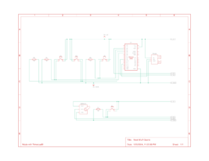
Schematic:

Circuit Design

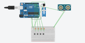
The circuit design includes:

  • Inputs:
    • Buttons for Jump, Rock, Bird, and Choice.
    • Ultrasonic sensor for crouching detection.
  • Outputs:
    • Servo motor for mechanical horse movement.

Circuit Setup:

Concept: 

“Catch the Horse” is an interactive, physically engaging game that combines a physical mechanical horse with a virtual environment. The game revolves around a man running after a horse, dodging obstacles, and strategising to catch the runaway animal. Using Arduino for hardware control and p5.js for the game logic, the project merges physical and digital interactivity in a seamless experience.

The game is designed for a single player or multiplayer to interact with both the physical and digital world, utilising buttons, sensors, and a motor to create a truly immersive gameplay environment.

Implementation Overview

The implementation is divided into two main components:

  1. Hardware (Arduino): Controls the physical setup, including buttons for gameplay interactions, an ultrasonic sensor for crouching detection, and a motor for the mechanical horse.
  2. Software (p5.js): Manages the game logic, animations, audio feedback, and communication with the Arduino.

Interaction Design

The player interacts with the game through a combination of physical actions and button presses:

  • Jump Button: Press to make the man jump over obstacles like rocks.
  • Rock Button: Press to launch rocks as obstacles for the man.
  • Bird Button: Press to release birds, which the man must dodge.
  • Lasso Button (Choice Button): Triggers a Choice Screen where the player selects between Skill and Luck to catch the horse.
  • Crouching: The ultrasonic sensor detects when the player crouches to avoid fences.

The game starts with a running man chasing a horse. Players must navigate these challenges to achieve victory. Victory conditions include successfully throwing the lasso and either rolling a winning dice number (Luck) or capturing the horse via a precise throw (Skill).

Arduino Code

The Arduino code serves as the bridge between the physical components and the digital game. Key features include:

  • Button Mapping: Jump, Rock, Bird, and Choice buttons are connected to Arduino pins, triggering serial communication to p5.js.
  • Ultrasonic Sensor Integration: Detects crouching and sends the signal to the game.
  • Motor Control: Starts and stops the physical horse motor based on game states.

The final Arduino sketch was robust and efficient, thanks to iterative improvements. One notable challenge was integrating the button connected to pin 5 (Choice Button) to handle multiple game states effectively. Solving this required careful adjustments to both Arduino and p5.js logic.

p5.js Code

The p5.js script handles the game logic, animations, and audio. Key highlights include:

  • Game States: Playing, Choice Screen, Game Over, and Game Won states dynamically adjust gameplay.
  • Animations: The running man and birds are controlled via sprite animations, providing a polished visual experience.
  • Audio Integration: Background music tracks play during specific game states (ninja.mp3 during Playing and horse.mp3 during Game Won), enhancing immersion.
  • Obstacle Logic: Rocks and birds have cooldowns to maintain game balance.

The most challenging part was ensuring smooth communication between the Arduino and p5.js. For example, handling simultaneous button presses and sensor inputs required careful synchronisation to avoid bugs.

You can try the game here:


Assignment 10: Testing Phase

Title: Testing Phase of “Catch the Horse” – Insights and Improvements

With the development of “Catch the Horse” completed, I conducted user testing to evaluate the intuitiveness, playability, and overall experience of the game. The goal of this phase was to observe how players interacted with the game, identify areas where they struggled, and determine how the gameplay mechanics could be made more intuitive and accessible.

User Testing Overview

During testing, participants were asked to engage with the game without receiving any prior instructions or guidance. The goal was to simulate the experience of a first-time player encountering the game. I recorded their interactions and noted points of confusion, questions they asked, and their overall feedback.

Observations and Findings

  1. What Users Figured Out on Their Own
    • Jump, Bird, and Rock Buttons:
      Players intuitively understood the jump mechanic and the functions of the bird and rock buttons. These actions had immediate visual feedback (e.g., the cowboy jumped, birds appeared, or rocks were thrown), which made the controls feel natural and responsive.
  2. What Needed Explanation
    • Lasso Button (Choice Button):
      Players struggled to understand how the lasso button worked. I had to explain that pressing the lasso button initiated the “Choice Screen” and that they could select between Skill or Luck to catch the horse.

      • Skill vs. Luck:
        The difference between the Skill and Luck options was unclear without explanation. Participants were unsure why they would choose one option over the other.
  • Interaction with Rocks and Birds:
    Although players understood how to use the rock and bird buttons, they were initially confused about how the cowboy was supposed to interact with these obstacles. For example, they weren’t sure if the rocks could be dodged or destroyed and if the birds required a specific action to avoid.

    What Worked Well

  • Physical Integration:
    The physical crouching mechanic, detected by the ultrasonic sensor, added an engaging and immersive element to the game. Users enjoyed the novelty of having to physically move to interact with the game.
  • Visual Feedback:
    Immediate visual feedback for the jump, bird, and rock mechanics allowed players to quickly understand these actions without explanation.
  • Game Flow and Balance:
    Cooldowns for the horse’s abilities (mud, fences, and booster) were well-received, as they maintained a fair and balanced gameplay experience.

    Lessons Learned

    • Mapping Between Controls and Gameplay:
      Intuitive mapping between controls and gameplay actions is critical. For example, the jump button and crouching were easy to grasp because the controls directly mirrored the in-game actions. However, abstract mechanics like the lasso required additional explanation due to their more complex interactions.
    • The Importance of Feedback:
      Immediate feedback helped players connect their actions to in-game effects. Enhancing feedback for less intuitive mechanics (like the lasso) will likely make the game easier to pick up.
    • Balancing Physical and Digital Gameplay:
      Players found the integration of physical actions (like crouching) and digital gameplay highly engaging. This balance between physical and virtual interaction should remain a cornerstone of the game’s design.

      Next Steps

      1. Add an Instructions Page or Tutorial:
        Include a brief tutorial or instructions page at the beginning of the game to explain the mechanics of the lasso button, Skill vs. Luck, and how to interact with obstacles like birds and rocks.
      2. Enhance In-Game Prompts:
        Add dynamic text prompts or animations during gameplay to guide players through challenging mechanics. For example:

        1. “Press J to Jump Over Rocks!”
        2. “Dodge Birds to Avoid Game Over!”

    Demonstration

Reading Reflection 8

Reuse and Recycle: A reflection on Design Meets Disability

In Design Meets Disability, the idea of trickle-down effects made a lot of sense to me. The tech market’s priorities often align with majority demand, leaving designs for the disabled marginalized in terms of research and funding. Sectors like fashion or mass-market tech get the lion’s share of attention, while solutions for disabilities often lack the investment they deserve.

However, the book highlights a crucial skill for designers: recognizing the applicability of existing technology to new problems. While creating something original is commendable, repurposing an established design can be equally impactful. Legal hurdles, like patents, may limit financial gains from such adaptations, but progress shouldn’t be confined by a competitive or profit-driven mindset. True innovation lies in recognizing the value of existing tools to accelerate development and as designers or artists, we have the benefit of the sky being the limit to our creativity. Thus, repurposing existing technology is never frowned over by our kind as artists have the ability to bring their own touch to any project.

Assignment 9: Final project Proposal

Title: Catch the Horse
Mechanical Horse.mp4 – Google Drive

Concept:

“Catch the Horse” is an interactive two-player game that blends physical and virtual gameplay to create an engaging experience. A physical mechanical horse and a digital cowboy chase are brought to life through Arduino and p5.js integration. The game revolves around strategy, reflexes, and decision-making, where one player controls a cowboy trying to catch a runaway horse, while the other player actively defends the horse using tools like mud, fences, and boosters. With immersive elements like crouching to dodge obstacles and precise timing challenges to throw a lasso, the game offers an interactive and entertaining experience.

Overview:

In “Catch the Horse,” a virtual horse escapes its stable and leaves the screen, triggering a motor that animates a physical mechanical horse placed beside the monitor. The cowboy avatar must chase after the horse, dodging obstacles and using a lasso to attempt capture. The horse player can make the chase challenging with mud, fences, and boosters, while the cowboy must rely on strategic decision-making and skill to win.

Gameplay Mechanics

The Cowboy’s Role (Player 1)

  • Chasing the Horse:
    • The cowboy avatar moves left and right using a joystick to dodge mud and other obstacles.
    • Physical crouching (detected by an ultrasonic sensor) is required to avoid fences thrown by the horse player.
    • At set intervals, the cowboy can attempt to throw a lasso to capture the horse or a bag of treats.
  • Lasso Mechanic:
    The cowboy has two options when throwing the lasso:

    1. Catch the Horse (Luck-Based):
      • A meter appears with an oscillating needle that moves slower, making it easier to time the throw.
      • If successful, the player rolls a virtual dice. A roll of 5 or 6 captures the horse; otherwise, the chase continues.
    2. Catch the Treats (Skill-Based):
      • The meter’s needle oscillates faster, requiring greater precision to time the throw.
      • Success guarantees the bag of treats, which stops the horse and ensures a win.
      • Failure results in no capture, and the chase continues. Speedometer meter with arrow for dashboard. - Vector. 30715312 Vector ...

The Horse’s Role (Player 2)

  • The horse player uses three buttons to evade capture:
    1. Mud Throw: Throws mud obstacles that the cowboy must dodge with the joystick.
    2. Fence Throw: Launches fences that the cowboy must crouch to avoid.
    3. Booster: Temporarily speeds up the horse, preventing the cowboy from throwing a lasso.
  • All buttons have cooldown periods to maintain fairness and balance. Robot Unicorn Attack 2 (Gameplay) Android / iOS - YouTube

Challenges and Solutions

  1. Mechanical Horse Durability:
    • The motor runs at a controlled speed to prevent stress on the fragile body.
  2. Button Cooldowns and Fairness:
    • Cooldown timers for the horse player’s buttons ensure balanced gameplay.
  3. Accurate Crouch Detection:
    • Calibrate the ultrasonic sensor to detect movement precisely while avoiding false triggers.

Winning Conditions

  • The cowboy wins if they:
    • Successfully throw the lasso and roll a 5 or 6.
    • Successfully capture the bag of treats.
  • The horse wins if:
    • The cowboy fails all lasso attempts, or the timer runs out.


Assignment 8: In class Exercises (Serial Communication)

Exercise 1 – Moving Ellipse

Prompt: Make something that uses only one sensor on Arduino and makes the ellipse in p5 move on the horizontal axis, in the middle of the screen, and nothing on Arduino is controlled by p5.
Arduino Code
Demonstration:

Exercise 2 – LED Brightness

Prompt: Make something that controls the LED brightness from p5

Arduino Code

P5.js Sketch

Demonstration:

Exercise 3 – Bouncing Ball

Prompt: Take the gravity wind example (https://editor.p5js.org/aaronsherwood/sketches/I7iQrNCul) and make it so every time the ball bounces one led lights up and then turns off, and you can control the wind from one analog sensor

Arduino Code

P5.js Sketch

Demonstration:

Assignment 7: How fairies play the piano

Concept:

For this assignment, my partner Fasya and I designed a musical instrument that merges digital and analog elements to create an interactive, light-based piano. Our idea centers around a glowing wand that functions as a control interface. When moved over the keys, the wand activates notes from the C major scale (C, D, E, F, and G) like magic, and the brightness of its glow determines the octave. We integrated a potentiometer to adjust brightness, allowing users to easily shift the octave up or down. Additionally, we added a switch to toggle the instrument off, which prevents accidental note activation—particularly useful to avoid unintended sounds from ambient light sources like flashlights.

Highlight:

To bring our vision to life, we used five photoresistors to detect light from the wand and mapped each sensor’s range to specific notes (C, D, E, F, and G) and their octave scales. By setting sensor thresholds from a default minimum to a maximum value that a flashlight might produce, we could dynamically adjust the octave based on the brightness the photoresistor detects. Essentially, the brighter the wand, the higher the octave, allowing for an expressive range in tone.

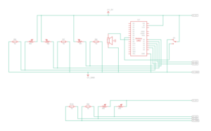
For the wand itself, we created a purple glow using a tricolored LED, giving the instrument an ethereal fairy-like visual quality. A potentiometer is attached to the LED to control brightness, making it easy for users to adjust octaves on the fly. The setup includes separate circuits for the keyboard and wand, creating flexibility for future enhancements, such as adding multiple wands for collaborative play.

Keyboard Code:

#include "pitches.h"
bool buttonState = false;
// Define the piezo buzzer pin
const int buzzerPin = 8;

// Define frequencies for each note across multiple octaves
const int fNotes[] = {NOTE_F4, NOTE_F5, NOTE_F6, NOTE_F7};  // Octaves of A
const int gNotes[] = {NOTE_G4, NOTE_G5, NOTE_G6, NOTE_G7};  // Octaves of B
const int cNotes[] = {NOTE_C4, NOTE_C5, NOTE_C6, NOTE_C7};  // Octaves of C
const int dNotes[] = {NOTE_D4, NOTE_D5, NOTE_D6, NOTE_D7};  // Octaves of D
const int eNotes[] = {NOTE_E4, NOTE_E5, NOTE_E6, NOTE_E7};  // Octaves of E

void setup() {
  // Initialize serial communication at 9600 bps for debugging
  Serial.begin(9600);
  pinMode(7,INPUT);
}

void loop() {
  // Array to store sensor values
  int sensorValues[5];
  int switchValue = digitalRead(7);
  if (switchValue == HIGH){
      buttonState = true;
  }

 
  // Read each sensor value and store in the array
  sensorValues[0] = analogRead(A3);  // f note
  sensorValues[1] = analogRead(A4);  // g note
  sensorValues[2] = analogRead(A0);  // C note
  sensorValues[3] = analogRead(A1);  // D note
  sensorValues[4] = analogRead(A2);  // E note

  // Play a note based on each sensor value
  for (int i = 0; i < 5; i++) {
    int note;
    if (sensorValues[i] < 850 || !buttonState) {
      // Stop any sound if the sensor value is below 900
      noTone(buzzerPin);
      continue;
    } else {
      // Map the sensor value (900 to 1100) to an index (0 to 3) for each note array
      int noteIndex = map(sensorValues[i], 850, 1100, 0, 3);

      // Assign the note based on the sensor index
      switch(i) {
        case 0: note = fNotes[noteIndex]; break;
        case 1: note = gNotes[noteIndex]; break;
        case 2: note = cNotes[noteIndex]; break;
        case 3: note = dNotes[noteIndex]; break;
        case 4: note = eNotes[noteIndex]; break;
      }
      
      // Play the mapped frequency on the piezo buzzer
      tone(buzzerPin, note);
    }
    
    // Delay to control the speed of tone change
    delay(100);
  }
}

Wand Code:

// *Interfacing RGB LED with Arduino 
// * Author: Osama Ahmed 

//Defining  variable and the GPIO pin on Arduino
int redPin= 9;
int greenPin = 10;
int  bluePin = 11;
int potPin = A2;
int sensorVal = 0;
double brightness = 0;

void setup() {
  Serial.begin(9600);
  //Defining the pins as OUTPUT
  pinMode(redPin,  OUTPUT);              
  pinMode(greenPin, OUTPUT);
  pinMode(bluePin, OUTPUT);
}
void  loop() {
  sensorVal = analogRead(potPin);
  brightness = (double)sensorVal / 1023;
  Serial.println(brightness);
  
  setColor(170, 0, 255, brightness); // Purple Color
  // delay(1000);
}
void setColor(int redValue, int greenValue,  int blueValue, double brightValue) {
  analogWrite(redPin, (double) redValue * brightValue);
  analogWrite(greenPin,  (double) greenValue  * brightValue);
  analogWrite(bluePin, (double) blueValue  * brightValue);
}

Demonstration:

Keyboard Circuit Schematic
Wand Circuit Schematic


Reading Reflection 7: Rant Continued

Thoughts on Pictures under Glass:

I share Bret Victor’s perspective on “pictures under glass” technology, and I believe touchscreen LEDs have overstayed their welcome in many fields. This includes devices like the Kindle—a non-glare touchscreen designed for reading that now also accommodates audiobooks. While these devices offer practical benefits, such as saving storage space and promoting a paperless world, they come at the cost of the rich sensory experience that traditional books provide.

Touchscreens have permeated so many areas of our lives, saturating us with constant notifications, flashing updates, and endless scrolling. This widespread use of touchscreens has left us overstimulated, as we’re constantly pulled in multiple directions by the same technology that now powers even our reading devices. This overstimulation detracts from the act of reading itself, making it harder to slow down and engage in the immersive, focused way that physical books invite. In fact, the Kindle’s interface, with its flat screen and standardized e-book format, feels more like another digital task than an invitation to read.

A physical book, by contrast, invites us to unplug, slow down, and focus. Its varied textures, the scent of the pages, and even the way it changes over time as it’s passed from one reader to the next all contribute to the act of reading as a sensory experience. Books are unique; each one feels different to the touch and engages the senses in ways that screens simply can’t emulate.

More than that, a well-worn book carries visible signs of love and use—cracked spines, dog-eared corners, or a few scribbled notes. These details create a sense of shared history and connection between readers across generations. No matter how advanced, a Kindle can never replicate that. Physical books leave an imprint not only on us but also of us, and in that way, they foster a relationship with readers that digital devices lack.

Reading Reflection 6

Thoughts on physical computing and how to do it:

Physical Computing’s Greatest hits and misses
Making Interactive Art: Set the Stage, Then Shut Up and Listen

In reading Physical Computing’s Greatest Hits and Misses and Making Interactive Art: Set the Stage, Then Shut Up and Listen, I got a sense that while physical computing has been around for a long time, the approach to creating interactive art has evolved. Rather than focusing on creating fixed meanings, artists are now encouraged to let meaning emerge through interaction, giving audiences more freedom in their interpretation.

From my own experiences visiting new media art installations in Paris and London, I’ve noticed that many installations still tend to be defined by the artist’s initial inspiration, which can limit the ways audiences experience them. One example is an installation I saw in the meditation room at the Museum of the Future. The setup involved placing your hands over a column that emitted vibrations, designed to create a relaxing, full-body sensation. However, instead of allowing us to engage directly with the sensations, an interpreter was there to tell us how to think and feel as we experienced it, even instructing us to close our eyes and envision a door. This guidance controlled our interpretation, making it harder to form a personal connection with the piece.

This experience reinforced what the readings suggest: interactive art is most impactful when artists “set the stage” but avoid overly directing the audience’s interpretation. By allowing viewers to find their own meaning in the experience, the connection to the art becomes more personal and engaging.

Assignment 6: Overspending Warning

Concept:

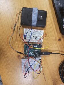
For this assignment, we were asked to control one LED in an analog manner and another in a digital manner. I chose to use a button switch to control one LED and a potentiometer for the other. For the digital component, I attached a button switch to my wallet’s card-ejection button so that whenever I try to access my credit card, a red LED lights up as a gentle warning to consider my spending. For the analog component, I connected a potentiometer to a blinking LED, allowing the speed of the LED’s blinking to be adjusted by turning the potentiometer. This setup demonstrates both analog and digital LED control in a creative, practical application.

Highlight:

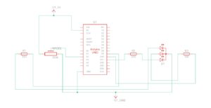
A key highlight of this project is my approach to keeping the analog and digital circuits distinct from each other. By treating them as separate circuits, I chose to use the Arduino’s 5V and 3.3V power outputs individually powering the digital circuit with 5V and the analog circuit with 3.3V. Additionally, I set up each circuit on separate breadboards, which makes it easy to distinguish between the two and ensures a clear, organized layout. This setup not only reinforces the conceptual differences between analog and digital control but also simplifies troubleshooting and testing.

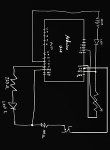
Hand-Drawn Schematic

For the coding aspect of this project, I organized the code by designating separate blocks for the analog and digital controls, clearly separated by comments. This structure makes the code easier to navigate and understand, as each section is dedicated to controlling one LED independently.

In the blinking LED project, I utilized the map function, as we covered in class, to control the blinking speed with the potentiometer. By mapping the potentiometer’s analog input range (0–1023) to a delay range (e.g., 50–1000 milliseconds), I was able to adjust the blink rate based on the potentiometer’s position.

int led = 11;

void setup() {
 Serial.begin(9600);

 pinMode(led, OUTPUT);
 pinMode(13, OUTPUT);
 pinMode(A2, INPUT);

}

void loop() {
//controlling led with a potentiometer
    int sensorValue = analogRead(A1);
    Serial.println(sensorValue);

    // Map the potentiometer value (0–1023) to a delay time (e.g., 50–1000 ms)
    int blinkDelay = map(sensorValue, 0, 1023, 50, 1000);

    // Blink the LED at a speed controlled by the potentiometer
    digitalWrite(led, HIGH); 
    delay(blinkDelay);        
    digitalWrite(led, LOW);    
    delay(blinkDelay);         

//Controlling Led with a Button
int buttonState = digitalRead(A2);
if (buttonState == LOW) {
digitalWrite(13, LOW);
} else {
digitalWrite(13, HIGH);
}

}

Demonstration:

Digital Circuit

Analog Circuit

Complete Setup

Assignment 5: Unusual Switch

Concept:

The inspiration for this project came from a common issue in my home: my siblings often leave kitchen drawers and cabinet doors open after grabbing snacks. This habit leads to my cat sneaking into these spaces, where she can hide for hours. To solve this, I came up with the idea of creating a simple sensor-based system that alerts my siblings when they forget to close a drawer or cabinet. By using a light sensor, this system can detect when a drawer or door is left open and activate a notification, such as an LED, to remind them to close it. This project combines basic electronics with a practical problem-solving approach to keep both the kitchen organized and my cat safe.

Highlight:

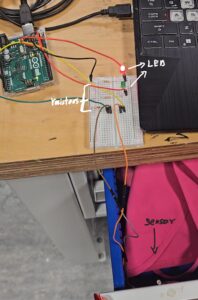
The highlight of this project was developing a functional switch system that alerts users when a drawer is left open. I began by connecting a light sensor to a 10k resistor in a voltage divider circuit, which allowed me to monitor light changes accurately. I added a red LED and a green LED, each with its own 330-ohm resistor, connected to digital pins 10 and 11.

void setup() {
  // initialize serial communication at 9600 bits per second:
  Serial.begin(9600);
  
  // Set pin modes for LEDs
  pinMode(10, OUTPUT); // Red LED
  pinMode(11, OUTPUT); // Green LED
}

// the loop routine runs over and over again forever:
void loop() {
  // read the input on analog pin A2:
  int sensorValue = analogRead(A2);
  
  // print out the value you read:
  Serial.println(sensorValue);
  delay(1);  // delay in between reads for stability

  if (sensorValue > 600) {
    // Turn on red LED and turn off green LED
    digitalWrite(10, HIGH);
    digitalWrite(11, LOW);
  } else {
    // Turn on green LED and turn off red LED
    digitalWrite(10, LOW);
    digitalWrite(11, HIGH);
  }
}

Then, using code adapted from Week 9 lecture slides, I programmed the LEDs to respond to light levels: the red LED illuminates when the sensor detects that a drawer is open, and the green LED lights up when the drawer is closed. Finally, I mounted the light sensor inside the drawer and tested the setup. As designed, the red LED serves as an alert when the drawer is open, while the green LED confirms it is securely closed. This project successfully provided a practical solution to alerting users to close drawers, helping prevent pets from accessing open spaces.

Setup

Demonstration: