Final Project

For my final project, I first decided to utilize NeoMatrix to create an interactive pixel art board. In the beginning everything was going okay, I spent a few nights trying to connect the wires to the tiny holes in the NeoMatrix and in the end connect two out of four boards, mainly because two other boards failed to light up. The soldering process was probably the hardest part of the entire project. Since I was not used to the machine and had barely any experience beforehand, I was left in quite a tough situation, with a bunch of burn marks and a hope which was ultimately extinguished after failing to connect a 16×16 board.

Although the situation was hard, I finished my code for the p5js end. A snipped of the most important bits can be seen below.

const WINDOW_WIDTH = 800
const WINDOW_HEIGHT = 400
const TILE_WIDTH = WINDOW_WIDTH/2
const TILE_HEIGHT = WINDOW_HEIGHT
const NUMBER_ROWS = 8
const NUMBER_COLUMNS = 8
const WIDTH = TILE_WIDTH/NUMBER_COLUMNS
const HEIGHT = TILE_HEIGHT/NUMBER_ROWS

let serial;

let pressed_id = 0;
let state = 0;
let r = 255;  
let g = 255;
let b = 255;
boxes = []

class Box{
  constructor(x, y, w, h, id){
    this.x_pos = x
    this.y_pos = y
    this.box_width = w
    this.box_height = h
    this.id = id
    this.clicked_state = 0
  }
  
  display(){
    if(this.clicked_state == 1){
      fill(255, 0, 0)
    }
    else{
      fill(255, 255, 255)
    }
    rect(this.x_pos, this.y_pos, this.box_width, this.box_height)
  }
}

function setup() {
  
  createCanvas(WINDOW_WIDTH, WINDOW_HEIGHT);
  background(220);
  
  id = 0
  for(let n = 0; n < 3; n++){
    for(let i = 0; i < NUMBER_ROWS; i++){
      box_rows = []
      for(let j = 0; j < NUMBER_COLUMNS; j++){
        append(box_rows, new Box(n*TILE_WIDTH+j*WIDTH, i*HEIGHT, WIDTH, HEIGHT, id))
        id++
        
      }
    append(boxes, box_rows)
    }
  }
}

function draw() {
  for(let i = 0; i < boxes.length; i++){
    for(let j = 0; j < NUMBER_COLUMNS; j++){
      boxes[i][j].display()
    }
  }
}

function mouseClicked(){
  for(let i = 0; i < boxes.length; i++){
    for(let j = 0; j < NUMBER_COLUMNS; j++){
      if(mouseX > boxes[i][j].x_pos && mouseX < boxes[i][j].x_pos+boxes[i][j].box_width &&
         mouseY > boxes[i][j].y_pos && mouseY < boxes[i][j].y_pos+boxes[i][j].box_width){
        // console.log("(" + boxes[i][j].x_pos + ", " + boxes[i][j].y_pos + ", " +boxes[i][j].id +")")
        
        if(boxes[i][j].clicked_state == 0){
          boxes[i][j].clicked_state = 1
        }
        else{
          boxes[i][j].clicked_state = 0
        }
        state = boxes[i][j].clicked_state
        pressed_id = boxes[i][j].id 
      }
    }
  }
}

function keyPressed(){
  if (key == " ") {
    // important to have in order to start the serial connection!!
    setUpSerial();
  }
}

// This function will be called by the web-serial library
// with each new *line* of data. The serial library reads
// the data until the newline and then gives it to us through
// this callback function
function readSerial(data) {
  ////////////////////////////////////
  //READ FROM ARDUINO HERE
  ////////////////////////////////////

  if (data != null) {
    // make sure there is actually a message
    // split the message
    let fromArduino = split(trim(data), ",");
    // if the right length, then proceed
    if (fromArduino.length == 1) {
      // only store values here
      // do everything with those values in the main draw loop
      
      // We take the string we get from Arduino and explicitly
      // convert it to a number by using int()
      // e.g. "103" becomes 103
      rVal = int(fromArduino[0]);
      // alpha = int(fromArduino[1]);
    }

    //////////////////////////////////
    //SEND TO ARDUINO HERE (handshake)
    //////////////////////////////////
    let sendToArduino = pressed_id + "," + state + "," + g + "," + r + "," + b  + "\n";
    console.log(pressed_id + "," + state + "," + g + "," + r + "," + b  + "\n")
    writeSerial(sendToArduino);
  }
}

The code ran perfectly when it came to execution. The tiles were matched with the pixel placement of the NeoMatrix, which went in a zigzag pattern. After reading many pages of documentation for the Adafruit electronics, I was able to properly display the selected pixel from the p5js screen. Although all seem dandy, disaster struck at 12am in the morning.

The serial connection was working properly and the Adafruit library was maintaining the pixel array. However, unbeknownst to me, who was testing the board with only one color, green, the board did not display colors properly. After realizing this fact, I set out to work and spent a good couple of hours trying to fix the issue. After reviewing the documentation for what felt like the hundredth time, the board was still not working. Within the NeoMatrix setup, there was a line called “NEO_GRB” which stands for Green Red Blue. Without the serial connection, this line would produce normal colors that were set on a pixel. However, when paired, the matrix would produce only green,  blue and turquoise. When changed to “NEO_RGB”, the pixel would be colored either red, blue or purple. No matter which way I tried, only two out of three colors would show up. By checking on similar issues online, I found that many people were met with the same issue, but little knew of how to help. I tried many possible solutions but none of them worked. With only 2 days left until the showcase and the deadline had already passed, I was forced to abruptly change my final project. I decided to recreate an Etch-A-Sketch.

I admit that it was my issue that I did not start the serial connection process sooner, but having finished both the code and physical part, I believed there to be no issue with the process. Unfortunately, some things are just bound to fail and to save myself tears I decided to not waste time on something that I would not be able to fix. At least, if I tried something else, I would have somewhat of a satisfactory product by the end. Although my original idea is something I am very much more proud of, I believe that navigating through this crisis taught me to think of every detail that could go wrong in the future.

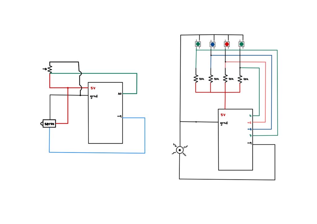
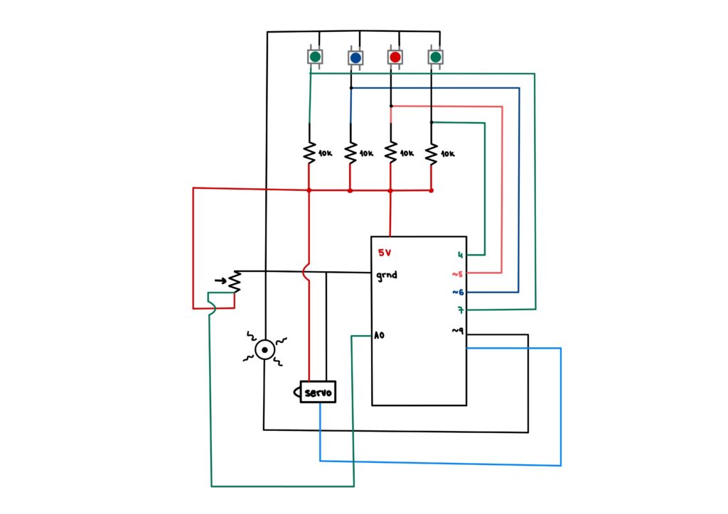
The Etch-A-Sketch was a project I believed to be very easily doable, even within the few days I had left. I already had code prepared for this project as it was also one of my original ideas at the start. All that was left was to create the physical components. By using potentiometers and a flex sensor, I would attempt to recreate a cult classic. The flex sensor would be used to detect rapid movement of an external device and delete the screen, imitating the shaking needed to erase an Etch-A-Sketch drawing.

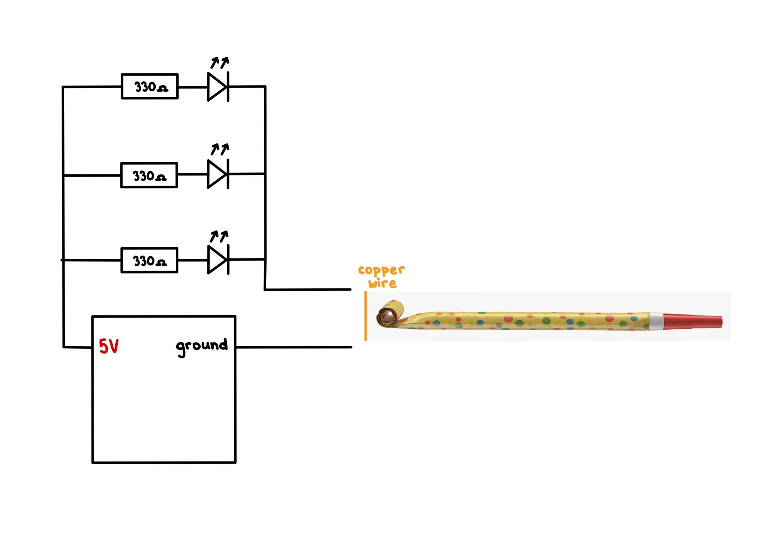
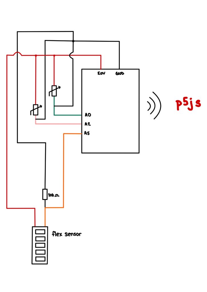
For the Arduino, the code was very simple. I only needed to collect the analog reads and calculate the angle of flex that would be used to clear the screen. The Arduino code can be seen below. The basic premise of the code is to gather the inputs from the flex sensor and the two potentiometers and send them to p5js for use. The LED code was used as control to check whether there was serial connection happening between Arduino and p5js.

// Measure the voltage at 5V and the actual resistance of your
// 47k resistor, and enter them below:
const float VCC = 4.98; // Measured voltage of Arduino 5V line
const float R_DIV = 47500.0;

// Upload the code, then try to adjust these values to more
// accurately calculate bend degree.
const float STRAIGHT_RESISTANCE = 37300.0; // resistance when straight
const float BEND_RESISTANCE = 90000.0; // resistance at 90 deg

int leftLedPin = 2;
int rightLedPin = 5;

void setup() {
  // Start serial communication so we can send data
  // over the USB connection to our p5js sketch
  Serial.begin(9600);

  // We'll use the builtin LED as a status output.
  // We can't use the serial monitor since the serial connection is
  // used to communicate to p5js and only one application on the computer
  // can use a serial port at once.
  pinMode(LED_BUILTIN, OUTPUT);

  // Outputs on these pins
  pinMode(leftLedPin, OUTPUT);
  pinMode(rightLedPin, OUTPUT);

  // Blink them so we can check the wiring
  digitalWrite(leftLedPin, HIGH);
  digitalWrite(rightLedPin, HIGH);
  delay(200);
  digitalWrite(leftLedPin, LOW);
  digitalWrite(rightLedPin, LOW);

  // start the handshake
  while (Serial.available() <= 0) {
    digitalWrite(LED_BUILTIN, HIGH); // on/blink while waiting for serial data
    Serial.println("0,0,0"); // send a starting message
    delay(300);            // wait 1/3 second
    digitalWrite(LED_BUILTIN, LOW);
    delay(50);
  }
}

void loop() {
  // wait for data from p5 before doing something
  while (Serial.available()) {
    digitalWrite(LED_BUILTIN, HIGH); // led on while receiving data

    int left = Serial.parseInt();
    int right = Serial.parseInt();
    if (Serial.read() == '\n') {
      digitalWrite(leftLedPin, left);
      digitalWrite(rightLedPin, right);

      int shaker = analogRead(A0);
      float flexV = shaker * VCC / 1023.0;
      float flexR = R_DIV * (VCC / flexV - 1.0);

      float angle = map(flexR, STRAIGHT_RESISTANCE, BEND_RESISTANCE,
                   0, 90.0);

      int sensor = analogRead(A2);
      delay(5);
      int sensor2 = analogRead(A5);

      Serial.print(angle);
      Serial.print(',');
      Serial.print(sensor);
      Serial.print(',');
      Serial.println(sensor2);
    }
  }
  digitalWrite(LED_BUILTIN, LOW);
}

To emulate the screen of a Etch-A-Sketch, p5js was utilized with a class that would serve as the tip of the drawing needle. The code, which can be seen below, received sensor data from Arduino in order to move the elements on screen as well as delete them.

class Ball{
  constructor(x_pos, y_pos, radius, color){
    this.x = x_pos
    this.y = y_pos
    this.r = radius
    this.c = color
    this.weight = 2
    this.x_prev = x_pos
    this.y_prev = y_pos
  }
  
  moveX(value){

    this.x = value; 
    
    
  }
  
  moveY(value){
    this.y = value;
  }
  
  display(){
    stroke(this.c)
    
    if(this.x_prev == 0 && this.y_prev == 0 ||
        this.x_prev == this.r && this.y_prev == this.r){
      strokeWeight(0)
    }
    else{
      strokeWeight(this.weight)
    }
    line(this.x_prev, this.y_prev, this.x, this.y)
    this.x_prev = this.x
    this.y_prev = this.y
  }
  
  changeCol(col){
    this.c = col;
  }
  
  changeWeight(weight_){
    this.weight = weight_
  }
}

let shaker = 0;
let rVal = 0;
let alpha = 0;
let left = 0;
let right = 0;

let canvas;
let current_theme = 255;
let button_state = 0;

let colorPicker;
let button;
let slider;

function setup() {
  canvas = createCanvas(600, 600);
  textSize(18);
  background(255)
  
  colorPicker = createColorPicker('#ed225d');
  colorPicker.position(width+5, 0);
  colorPicker.size(50,200)
  
  button = createButton("Switch Theme");
  button.position(width+5, 205)
  button.size(50,50)
  button.mousePressed(switchTheme)
  button.style('font-size', '10px')
  
  slider = createSlider(0, 10, 0, 1);
  slider.position(width-35, 320);
  slider.style("transform","rotate(90deg)");
  
  button2 = createButton("Save Drawing");
  button2.position(width+5, 400)
  button2.size(50,50)
  button2.mousePressed(saveDrawing)
  button2.style('font-size', '10px')

  mover = new Ball(rVal, alpha, 2, "#000")
  
  clearScreen();
}

function draw() {
  let val1 = map(rVal, 0, 1023, mover.r, width-mover.r)
  let val2 = map(alpha, 0, 1023, mover.r, height-mover.r)
  
  mover.display();
  mover.moveX(val1);
  mover.moveY(val2);
  
  mover.changeCol(colorPicker.color())
  
  clearScreen();
  
  mover.changeWeight(slider.value()+2)
  // one value from Arduino controls the background's red color
  //background(map(rVal, 0, 1023, 0, 255), 255, 255);

  // the other value controls the text's transparency value
  //fill(255, 0, 255, map(alpha, 0, 1023, 0, 255));

//   if (!serialActive) {
//     text("Press Space Bar to select Serial Port", 20, 30);
//   } else {
//     text("Connected", 20, 30);
    

//     // Print the current values
//     text('rVal = ' + str(rVal), 20, 50);
//     text('alpha = ' + str(alpha), 20, 70);

//   }
  // let writer = createWriter('newFile.txt');
  // writer.write([rVal, alpha]);
  // writer.close()
}

function keyPressed() {
  if (key == " ") {
    // important to have in order to start the serial connection!!
    setUpSerial();
  }
}

function clearScreen(){
  if(shaker > 200){
    background(current_theme)
  }
}

function switchTheme(){
  button_state++;
  if(button_state >= 2){
    button_state = 0
  }
  if(button_state == 0){
    background(255)
    current_theme = 255
  }
  else{
    background(0)
    current_theme = 0
  }
}

function saveDrawing(){
  save(canvas, "myCanvas", 'png');
}


function readSerial(data) {
  ////////////////////////////////////
  //READ FROM ARDUINO HERE
  ////////////////////////////////////

  if (data != null) {
    // make sure there is actually a message
    // split the message
    let fromArduino = split(trim(data), ",");
    // if the right length, then proceed
    if (fromArduino.length == 3) {
      // only store values here
      // do everything with those values in the main draw loop
      
      // We take the string we get from Arduino and explicitly
      // convert it to a number by using int()
      // e.g. "103" becomes 103
      shaker = int(fromArduino[0]);
      rVal = int(fromArduino[1]);
      alpha = int(fromArduino[2]);
    }

    //////////////////////////////////
    //SEND TO ARDUINO HERE (handshake)
    //////////////////////////////////
    let sendToArduino = left + "," + right + "\n";
    writeSerial(sendToArduino);
  }
}

Although the code is quite simple, due to the time constraint posed on me after the initial project failed, there was little to be done to increase the complexity of it. To give the users some degree of freedom, I added a color picker, a stroke changer and buttons to change the theme as well as save the canvas drawing, if they wish to do so. The screen is deleted upon shaking the shaker that comes with the Arduino.

Arduino and Circuit sketch

Reflection

This project was quite fun to work on. Although my initial idea failed, I am happy to have produced at least something to show my passion for Interactive Media. I would love to rework my initial project and attempt to make it work after I have finished with this class. Knowing what went wrong and how I could have fixed it with a saner state of mind might just be what pushed me to pursue Interactive Media and Physical Computing in the long run. For now, I am just grateful to have a physical product with me to show at the Showcase and even though I wish I could have done more, I realized it is sometimes important to start anew in order to learn more than I would have if I had continued to be stuck on the broken project. I loved taking Introduction to Interactive Media this semester and I hope that by continuing my Interactive Media Minor journey, I will be able to learn much more about both coding and the physical components that bring our code to life.

Week 11 – Serial Communication

Task 1:

make something that uses only one sensor on arduino and makes the ellipse in p5 move on the horizontal axis, in the middle of the screen, and nothing on arduino is controlled by p5

Code:

For the code, I used the Arduino and p5js code that was given to us in the class and edited it to suit my needs of moving the horizontal object with the help of a potentiometer. The code shown below is what I wrote in order to move the ellipse on the horizontal axis. As the task was quite simple, I also made the background change colors and gave the ellipse a “trail” effect by changing the transparency.

function draw() {
  var var1 = map(map(rVal,0, 1023, 0, width/2), 0, width/2, 150, 200);
  var var2 = map(map(rVal,0, 1023, 0, width/2), 0, width/2, 200, 50)
  background(var1, var2, var2, 0.9)

  if (!serialActive) {
    fill("black")
    text("Press Space Bar to select Serial Port", 20, 30);
  } else {

    noStroke()
    ellipse(map(rVal, 0, 1023, 50, width-50), height/2, map(rVal, 0, 1023, 5, 50))
  }
}

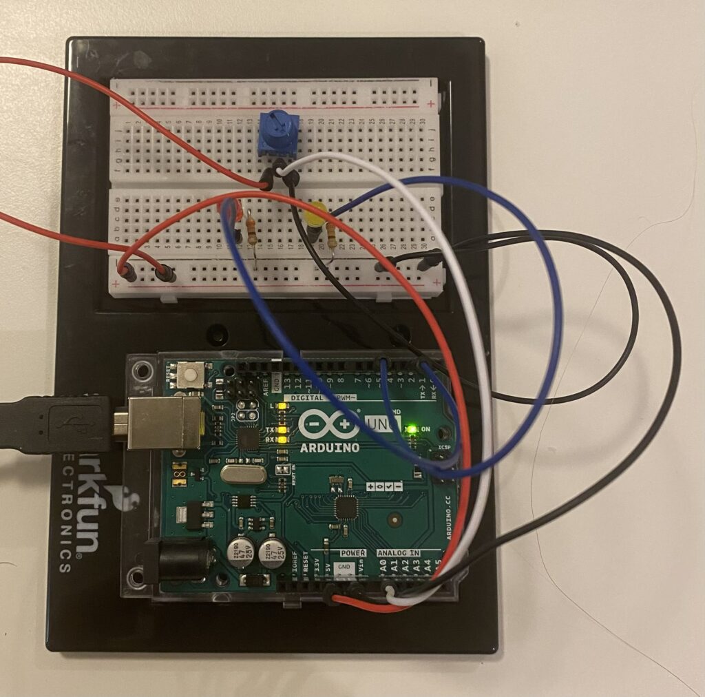
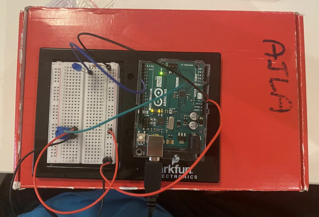
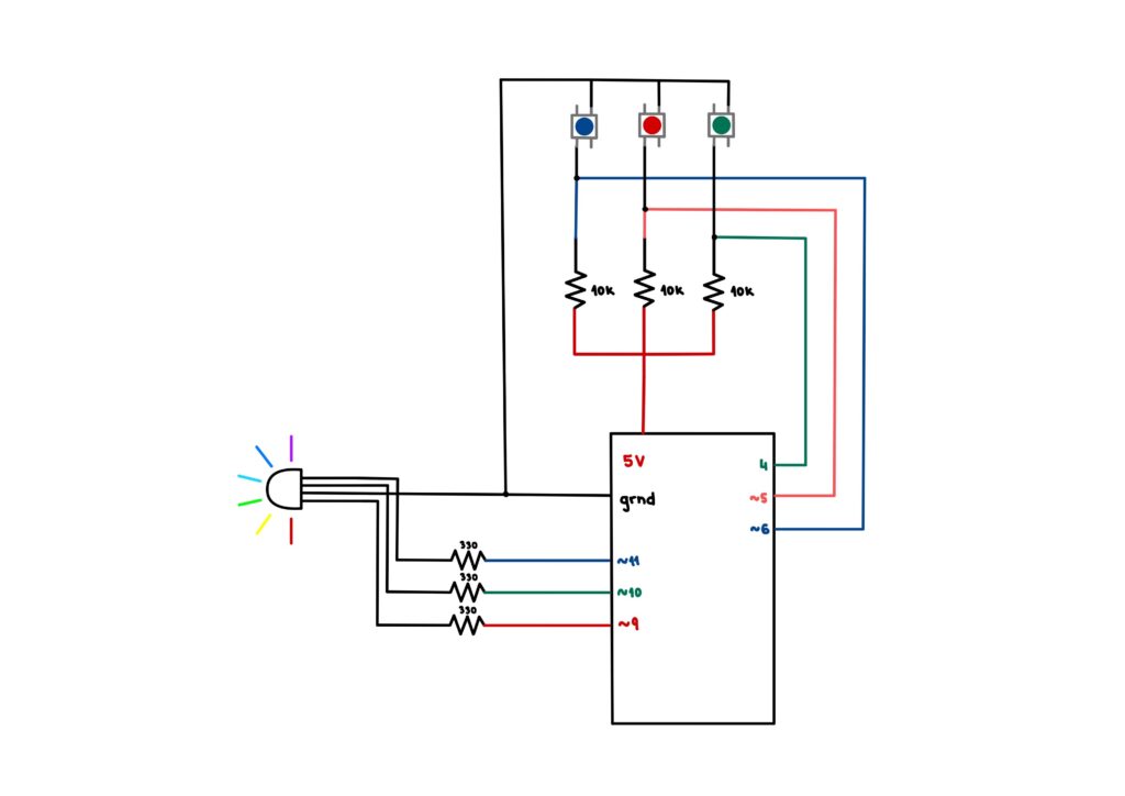
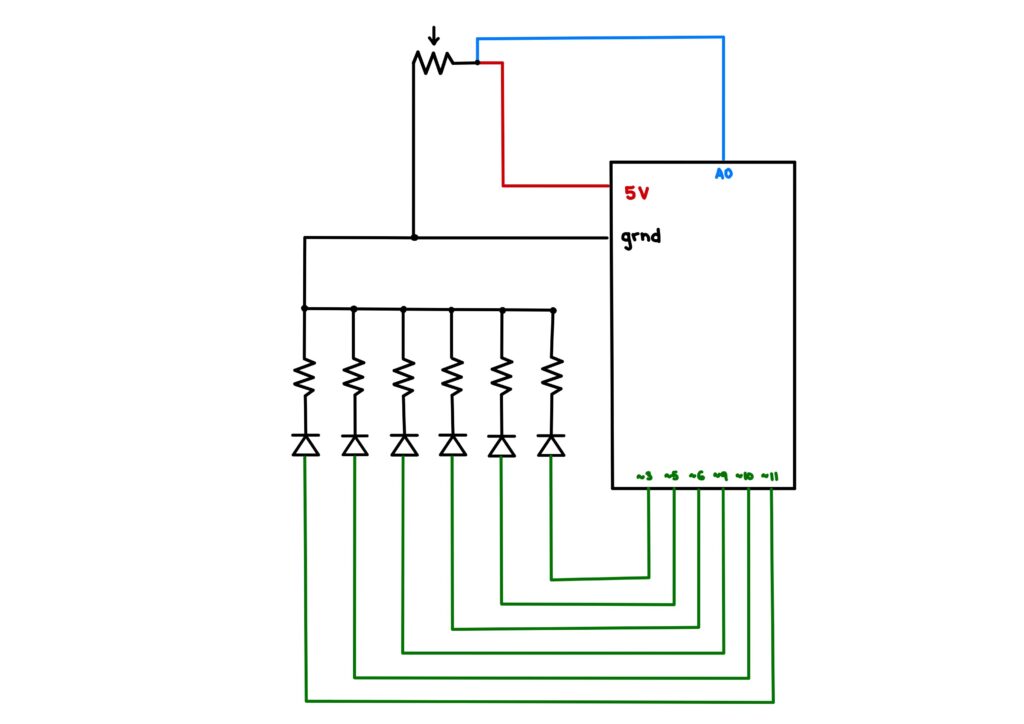
Picture of the circuit (The LEDs are used to check the wiring):

Task 2:

make something that controls the LED brightness from p5

Code:

As with the previous task, I used the already given code in order to change the brightness of the LED from p5js. However, I changed the digitalWrite() of the right LED (which was connected to pin 5 and could thus produce analog output) to analogWrite(). To change the brightness, I used a HTML slider in p5js. By extracting the value of the slider and sending the data to the right LED, I was able to change the brightness. Additionally, I changed the background color from black to white depending on the brightness of the LED such that the code is more intuitive.

function setup() {
  createCanvas(640, 480);
  textSize(18);
  
  slider = createSlider(0, 255, 0); // indicate the value range for slider
  slider.position(width/2-150, height/2);
  slider.style('width', '300px');
}

function draw() {
  var brightness_ = map(slider.value(), 0, 255, 0, 255);

  background(brightness_)
  
  if (!serialActive) {
  } else {
    right = brightness_;
  } 
}

The circuit looks the same as the one of the previous task but without the potentiometer.

Task 3:

take the gravity wind example and make it so every time the ball bounces one led lights up and then turns off, and you can control the wind from one analog sensor

Code:

Combined with the code given in class before, I used the gravity example code for the assignment. By allowing for minor changes, I was able to establish communication from both p5js to Arduino (LED lighting up) and vice versa (potentiometer controlling the wind). While most of the code is from the example, I have annotated the parts which I have added below.

/* Week 11.2 bidi serial example
 * Originally by Aaron Sherwood
 * Modified by Mangtronix
 *
 * Add this library to Sketch files
 *  https://github.com/mangtronix/IntroductionToInteractiveMedia/blob/master/code/p5.web-serial.js files
 *
 * You must include this line in your index.html (in Sketch Files) to load the
 * web-serial library
 *
 *     <script src="p5.web-serial.js"></script>
 *
 * Arduino code:
 * https://github.com/mangtronix/IntroductionToInteractiveMedia/blob/master/code/Week11Serial.ino
 */

let left = 0;
let right = 0;
let rVal = 0;

function setup() {
  createCanvas(640, 480);
  textSize(18);
}


let velocity;
let gravity;
let position;
let acceleration;
let wind;
let drag = 0.99;
let mass = 50;

function setup() {
  createCanvas(640, 360);
  noFill();
  position = createVector(width/2, 0);
  velocity = createVector(0,0);
  acceleration = createVector(0,0);
  gravity = createVector(0, 0.5*mass);
  wind = createVector(0,0);
}

function draw() {
  background(255);
  applyForce(wind);
  applyForce(gravity);
  velocity.add(acceleration);
  velocity.mult(drag);
  position.add(velocity);
  acceleration.mult(0);
  // CONSTRAIN ELLIPSE SUCH THAT IT DOES NOT MOVE OFF SCREEN
  ellipse(constrain(position.x,mass/2, width-mass/2),position.y,mass,mass);
  if (position.y > height-mass/2) {
      // LIGHT UP LED ON COLLISION
      right = 1;

      velocity.y *= -0.9;  // A little dampening when hitting the bottom
      position.y = height-mass/2;
    }
  else{
    // LED SWITCHES OFF WHEN THERE IS NO COLLISON
    right = 0;
  }
  
  // CONTROL WIND WITH POTENTIOMETER READING
  if(!serialActive){
  }
  else{
    wind.x = map(rVal, 0, 1023, -1, 1)
  }
}

function applyForce(force){
  // Newton's 2nd law: F = M * A
  // or A = F / M
  let f = p5.Vector.div(force, mass);
  acceleration.add(f);
}

function keyPressed(){
  if (keyCode==UP_ARROW){
    mass=random(15,80);
    position.y=-mass;
    velocity.mult(0);
  }

  // REMOVED RIGHT AND LEFT KEY FOR WIND

  //  CONNECTING TO PORT
  if (key == " ") {
    setUpSerial();
  }
}

// CODE FROM CLASS
function readSerial(data) {
  ////////////////////////////////////
  //READ FROM ARDUINO HERE
  ////////////////////////////////////

  if (data != null) {
    // make sure there is actually a message
    // split the message
    let fromArduino = split(trim(data), ",");
    // if the right length, then proceed
    if (fromArduino.length == 1) {
      // only store values here
      // do everything with those values in the main draw loop
      
      // We take the string we get from Arduino and explicitly
      // convert it to a number by using int()
      // e.g. "103" becomes 103
      rVal = int(fromArduino[0]);
      // alpha = int(fromArduino[1]);
    }

    //////////////////////////////////
    //SEND TO ARDUINO HERE (handshake)
    //////////////////////////////////
    let sendToArduino = left + "," + right + "\n";
    writeSerial(sendToArduino);
  }
}

Video:

Reflection:

This assignment, although not as creative as the rest, was quite interesting. Setting up serial communication between p5js and the Arduino is something I found quite hard to understand in class, but since the assignment involved three Tasks, it became quite easy to navigate both the code and hardware side of things. One of the challenges I faced was failing to remember that Arudino does not work on Safari and that I need to re-compile code in order for it to run. It took me quite some time to remember that I needed to switch browsers for my code to run. However, I take both of these as valuable lessons and hope that I will not forget such details in the future, just to save myself from stressing as much as I did when beginning this project. All in all, I wish to do more creative stuff with the two components, which I hope can be seen in my final project.

Week 9 – Musical Instrument

by Ajla and Hana

Concept

This week’s assignment was to create a simple musical instrument using the Arduino. Hana and Ajla decided to create a simplified piano and drum. In order to do so, we utilized switches and a servo motor. We controlled the speed of the servo motor using a potentiometer. The notes are played by pressing the buttons. The buttons stop producing noise when released.

Implementation

To implement our musical instrument, we used a potentiometer, switches, a piezoelectric buzzer, resistors, wires and an Arduino. By connecting the switches in parallel we were able to preserve voltage across all components. Even though it was possible to connect everything on one breadboard, we decided to separate it in order to make the instrument user friendly. Furthermore, since many digital inputs were used, the separation ensured that there would not be any overcrowding while presenting the final product.The sketches below show both the two Arduino setup we used and one Arduino setup.

The code was written for both Arduino. Hana wrote the code for the switches and Ajla wrote the code for the drum. The drum was made using a metal screw, silk ribbon and tape which was attached to the servo hand. By pressing the four switches, notes, stored in an array, were played. The drum hit a piece of cardboard in order to produce noise.

Two Arduino
One Arduino

Here is the code for playing the notes:

// if button1 is pressed, playes first note
  if(button1State==1) {
    tone(9, notes[0]);
  }

// if button2 is pressed, playes second note

  if(button2State==1) {
    tone(9, notes[1]);
  }

// if button3 is pressed, playes third note

  if(button3State==1) {
    tone(9, notes[2]);
  }

// if button4 is pressed, playes fourth note

  if(button4State==1) {
    tone(9, notes[3]);
  }

// if buttons are release, no note is played

  if(button1State==0 && button2State==0  && button3State==0 && button4State==0) {
    noTone(9);
  }
  
  
  delay(1);  // delay in between reads for stability

Here is the code that ran the servo in a 90 degree range:

void loop() {
  int p_value  = analogRead(p_meter);

  int value = map(p_value, 0, 1024, 10, 20);
  for (int i=45; i<90; i += value) {
    pos1 = 0 + (i*2);          // servo1 from 0 to 90 degrees
    myservo1.write(pos1);      // move the servo
    delay(50);  
  }
 
  for (int i=45; i<90; i += value) {
    pos1 = 90 - i*2;           // servo1 from 90 to 0 degrees
    myservo1.write(pos1);      // move the servo
    delay(50);
  }
}

Challenges

The assignment came with a few challenges. Firstly, since the piezoelectric buzzer cannot take multiple inputs at once, it was important to play each note once, without pressing others since that would destroy the quality of the sound. Secondly, the notes play continuously if the button is pressed, even once. That is why we added the last if statement that checks whether all buttons are not pressed, in which case it plays no sound. Thirdly, the servo is quite tricky to use at high speeds. It gets more imprecise as the speed goes up. So, controlling it with the potentiometer was quite hard to do precisely. Lastly, since the angle of motion changes as the speed increases, it was hard to mount the servo on anything as it would immediately fall down once the speed was changed. This became quite frustrating that we decided to just hold the servo in the end to showcase the tempo of the “drum”. All in all, this assignment came with quite a few challenges. Some of them we tried to attempt and won, such as the notes, but some of them remain to be defeated due to the lack of time and materials we had at the time of making this project.

Reflection (Ajla)

I am not very musically inclined. That is why it was quite hard to come up with any ideas for this project and why I wish the theme was a bit more open. However, I have learned quite a bit by attempting this project. The servo, although precise at low speeds, is something that gave me quite a headache when connected to a potentiometer. Since it rotates only 180 degrees, there is a limited amount of freedom I had while working on it which is something I do not like as a Computer Science major. The code could not make up for its shortcomings and I became quite frustrated because of that. However, it is important to learn from such experiences and try again in the future. Although I finished this assignment, I plan to work with theservo more in the future such as to learn how to make up for the drawbacks of its hardware.

Week 9 – RGB Color Mixer and Potentiometer Intensity Scale

Concept

For this week’s assignment we were to utilize digital and analog read and write to control some LEDs. For the digital component, I built a circuit that utilizes three switches and an RGB LED to create a simple RGB color mixer. It was a pretty straightforward concept that utilized a component we had not talked about in detail during class.

Simple RGB Color Mixer

Implementation

To implement this circuit I used an RGB LED, three switches, resistors and wires and an Arduino. The circuit was pretty simple and utilized some knowledge on parallel connections which can be seen in the diagram below:

The RBG diode functions as a three-in-one diode and displays 7 colors (including white which I know might not be a color) when used for digital output. To run the switch, I wrote some code for the Arduino which can be bound below

// Diode output initialization
const int red_o = 9; 
const int green_o = 10;
const int blue_o = 11;

// Diode input initialization
const int red_i = 5; 
const int green_i = 4;
const int blue_i = 6;

// Diode counters initialization
int b_counter = 0;
int r_counter = 0;
int g_counter = 0;

void setup(){
  // Input pin modes for the diode inputs
  pinMode(red_i, INPUT);
  pinMode(blue_i, INPUT);
  pinMode(green_i, INPUT);

  // Output pin modes for the diode outputs
  pinMode(red_o, OUTPUT);
  pinMode(green_o, OUTPUT);
  pinMode(blue_o, OUTPUT);
  
  // Debugging
  Serial.begin(9600);
}


void loop(){
  // Button state initialization
  int redButtonState = digitalRead(red_i);
  int blueButtonState = digitalRead(blue_i);
  int greenButtonState = digitalRead(green_i);

  /* 
  Color mixing options:

  Red -> Red diode output
  Green -> Green diode output
  Blue -> Blue diode output

  Cyan -> Blue and green diode output
  Purple/Magenta -> Red and blue diode output
  Yellow -> Red and green diode output

  White -> All three diode output

  */
  
  if (blueButtonState == LOW) {
    b_counter++;
    delay(1000);
  }

  if (redButtonState == LOW) {
    r_counter++;
    delay(1000);
  }

  if (greenButtonState == LOW) {
    g_counter++;
    delay(1000);
    Serial.println(g_counter);
  }

  if (g_counter == 1 && b_counter == 1 && r_counter == 1) {
    digitalWrite(red_o, HIGH);
    digitalWrite(green_o, HIGH);
    digitalWrite(blue_o, HIGH);
  }
  else if (g_counter == 1 && b_counter == 1) {
    digitalWrite(red_o, LOW);
    digitalWrite(green_o, HIGH);
    digitalWrite(blue_o, HIGH);
  }

  else if (g_counter == 1 && r_counter == 1) {
    digitalWrite(red_o, HIGH);
    digitalWrite(green_o, HIGH);
    digitalWrite(blue_o, LOW);
  }

  else if (r_counter == 1 && b_counter == 1) {
    digitalWrite(red_o, HIGH);
    digitalWrite(green_o, LOW);
    digitalWrite(blue_o, HIGH);
  }
  
  else if (b_counter == 1) {
    digitalWrite(red_o, LOW);
    digitalWrite(green_o, LOW);
    digitalWrite(blue_o, HIGH);
  }
  
  else if (r_counter == 1) {
    digitalWrite(red_o, HIGH);
    digitalWrite(green_o, LOW);
    digitalWrite(blue_o, LOW);
  }
  
  else if (g_counter == 1) {
    digitalWrite(red_o, LOW);
    digitalWrite(green_o, HIGH);
    digitalWrite(blue_o, LOW);
  }

  else {
    digitalWrite(red_o, LOW);
    digitalWrite(green_o, LOW);
    digitalWrite(blue_o, LOW);
  }

  // Counters for diodes
  // Work on 1/0 basis
  if(b_counter >= 2){
    b_counter=0;
  }
  
  if(r_counter >= 2){
    r_counter=0;
  }

  if(g_counter >= 2){
    g_counter=0;
  }

  // Debugging
  // Serial.print(b_counter);
  // Serial.print(" ");
  // Serial.print(r_counter);
  // Serial.print(" ");
  // Serial.println(g_counter);
}

Challenges

In the beginning I hoped to join both the analog and digital components of the assignment, but after finishing the digital (RGB color mixer), I soon realized that I do not have enough power to put both on a breadboard as my computer was not allowing me to proceed onwards. The idea was to increase the intensity of the RGB colors, once selected through the switches by using a potentiometer. Unfortunately, since it did not work even though I tried adding more power to the circuit, I decided to recreate the concept on a separate breadboard.

Potentiometer Intensity Scale

Implementation

To implement this circuit, I used 6 LEDs, a potentiometer, resistors and wires, as well as an Arduino. The LEDs and the switch were connected in parallel to preserve the voltage across components. The LEDs and the switch were then connected to PWM outputs and analog input respectively. The diagram of the circuit is below:

To run the circuit I wrote some Arduino code which utilized the mapping function in order to sequentially light up the diodes according to the potentiometer reading.

// Potentiometer input initialization
const int p_meter = A0;

// Diode output initialization
const int p_1 = 3;
const int p_2 = 5;
const int p_3 = 6;
const int p_4 = 9;
const int p_5 = 10;
const int p_6 = 11;


void setup() {
  // Potentiometer input
  pinMode(p_meter, INPUT);

  // Diode output
  pinMode(p_1, OUTPUT);
  pinMode(p_2, OUTPUT);
  pinMode(p_3, OUTPUT);
  pinMode(p_4, OUTPUT);
  pinMode(p_5, OUTPUT);
  pinMode(p_6, OUTPUT);

  // Debugging
  Serial.begin(9600);
}

void loop() {
  // Getting reading from potentiometer
  int potentiometer = analogRead(p_meter);

  // Mapping the reading to a value between 0 and 60
  // since there are 6 diodes
  // The interwal of each diode is hence 10
  int map_p = map(potentiometer, 0, 1023, 0, 60);
  
  // The logic is the same for each diode
  // If the value of the map is in a range of 10
  // respectful to the diode's range, then map the 
  // range of 10 to an increase in brightness of the diode
  if(map_p > 0 && map_p <= 10){
    int value1 = map(map_p, 0, 10, -10, 255);
    analogWrite(p_1, value1);
  }
  // Otherwise, turn off the diode
  else if(map_p == 0){
    analogWrite(p_1, 0);
  }
  if(map_p > 10 && map_p <= 20){
    int value2 = map(map_p, 10, 20, -10, 255);
    Serial.println(value2);

    analogWrite(p_2, value2);
  }
  else if(map_p < 10){
    analogWrite(p_2, 0);
  }
  if(map_p > 20 && map_p <= 30){
    int value3 = map(map_p, 20, 30, -10, 255);
    analogWrite(p_3, value3);
  }
  else if(map_p < 20){
    analogWrite(p_3, 0);
  }
  if(map_p > 30 && map_p <= 40){
    int value4 = map(map_p, 30, 40, -10, 255);
    analogWrite(p_4, value4);
  }
  else if(map_p < 30){
    analogWrite(p_4, 0);
  }
  if(map_p > 40 && map_p <= 50){
    int value5 = map(map_p, 40, 50, -10, 255);
    analogWrite(p_5, value5);
  }
  else if(map_p < 40){
    analogWrite(p_5, 0);
  }
  if(map_p > 50 && map_p <= 60){
    int value6 = map(map_p, 50, 60, -10, 255);
    analogWrite(p_6, value6);
  }
  else if(map_p < 50){
    analogWrite(p_6, 0);
  }
}

Challenges

As stated above, I was displeased that the intensity factor was not visible within one circuit. For this circuit, the hardest part was the mapping of the values such that the code runs properly. It took some time to realize that some of the diodes were broken and were not lighting up. Since I worked a diode at a time, the fact that one would just not light up was very frustrating. It is important to check diodes before starting, which is something I will do from now on.

Reflection

This assignment was very interesting to me. Since I never worked individually on a circuit that involves code, deducing how the Arduino works in accordance to the circuit I built was a very enriching experience. The frustration over faulty components is inevitable while working with electronics but it goes to show that code is not the only thing that might mess up the end product. In the future, I wish to be able to work on a larger breadboard with a larger power input so that my laptop would not prevent me from adding as many components as I want.

Week 8 – Birthday Switch

Concept

For this week’s assignment we were to create an unusual switch. Since it was one of my suitemates birthday, I decided to create a switch using a birthday blower. The idea was that it would open and hit a grounding wire and connect it to another grounding wire which would close the circuit consisting of three diodes in parallel.

The Circuit

The circuit was pretty straightforward to implement. Having taken A2 Level Physics, I still remember most of the content from Electricity and Circuits. Since voltage divides over elements (Three 2.0-2.4V diodes) in series, the 5.0V supply was not enough to run the circuit in series. Hence, I decided to connect them in parallel and maintain the same voltage across the different components. Below is the circuit diagram.

Figure 1. Circuit diagram

In order to connect the two grounding wires, I used copper wire/tape. By attaching the two ends of the grounding wires to a piece of double-sided tape, and appending the copper wire to the end of the birthday blower, I was able to close the circuit. The challenging part was aiming the end of the device such as to close the circuit properly. It took a few tries in order to get a hand of it, but I was ultimately able to aim it correctly and light up the diodes.

Reflection

This was probably one of my favorite assignments in the class to date. It made me feel extremely happy when the diodes lit up, even though the circuit was bound to work. Unfortunately, one of the diodes was faulty and as I was setting everything up, I thought that the circuit was bad. After changing the diode, everything worked, but it was a good lesson on having patience (because I was honestly running out of it). It would have been more fun to mount the board and arduino on a wall so that I can stand properly while closing the circuit, but since everything worked out in the end, I was very pleased with this week’s assignment outcome.

Video

Midterm Project – Final

Boy Who Cried Wolf: The Game

 To play the game click this link -> Boy Who Cried Wolf: The Game

Link to fully commented code -> Boy Who Cried Wolf: The Game (code)

૮꒰ ˶• ༝ •˶꒱ა. ૮꒰ ˶• ༝ •˶꒱ა  ૮꒰ ˶• ༝ •˶꒱ა. ૮꒰ ˶• ༝ •˶꒱ა. ૮꒰ ˶• ༝ •˶꒱ა

Process

Design

To start, I created a few pixel images that I would use for the game. I created three types of sheep, the shepherd, wolf and the trees. To create the wolf and the sheep, I took inspiration from the web (sheepwolf) but the boy and the trees are original creations. All of the images were created and animated using Piskel.

The boy is dressed in traditional Bosniak male clothing, the fes, vest (prsluk / džemadan), trousers (šalvare / shalwar or čakšire / çakşır), belt (bensilah) and shoes (opanci). The wolf looks very thin which represents his hunger

Using the images and Powerpoint (very handy program) , I created the start screen, as well as the winning and losing screens which are pictured below.

Implementation

The implementation process was quite straightforward, get the player to move the sheep in and around the pen. Unfortunately, the logic behind the game was not quite as straightforward. Having completed 90% of the game, I was stuck on the sheep and pen interaction for almost a whole day. Although that might not seem very bad, I was thinking of quite elaborate solutions that would calculate the depth of the interacting shapes which would translate into prohibiting the interaction. In the end, I went with the easiest solution and that is *drumroll* a lot of logical comparisons and arithmetic operations 🙁 . As a Computer Science student, I hate having my code look like a third grade maths notebook. However, running out of time forced me to take extreme measures and settle with the basic approach.

Other than the issues with object interactions, I was quite pleased with the flow of my programming. Although I really dislike working under pressure, working the code out was quite satisfying once I finalised the project.

Reflection

The project was very interesting to work on. Since I have made a simple game before, I knew my way around Object Oriented Programming, but what came as a surprise was that I am not yet capable of understanding the sizing of the canvas I am working on. The game is not at all scaleable. Although the variables such as number of sheep and their size are, the screen will not adapt to the change of values the way it should without going deep into the code and fixing it. In the future, I wish to make my games fully capable of resizing at anyone’s will. This may not be something that is done in re, but understanding the principles of canvas sizing will undoubtedly help me understand the greater scheme of things – responsive web design.

Midterm Progress – The Boy Who Cried Wolf

Concept

For my midterm project, I decided to make a game based on one of my favorite fables, The Boy Who Cried Wolf! The story goes that the boy, a shepherd, gave a false alarm to a village about a wolf coming to attack their sheep. Having done it two times, the third time, when a wolf was actually coming, the villagers did not believe him, leaving the sheep dead. There is a valuable lesson in this story, but as a child, I always wished they had saved the sheep. Why not believe the third time, you know, just in case? So, I decided to create a game in which a shepherd needs to collect his sheep into a pen before the wolf arrives to eat them.

Progress

For now, I have created the sheep and shepherd graphics and shapes which are underneath the images. The shepherd moves the sheep as he gets close to them and the sheep move around each other if they get too close. What is left is the sheep pen and the interactions concerning it. As for the graphics that are left, I intend on making the wolf, start and end screens, all pixelated as that is what I aim for the game to look like. I have also created the tree graphics which I will place around the screen.

Challenge

The most challenging part as of now is the sheep and pen interactions. Since the sheep move by 15 pixels as the shepherd approaches, it will take some thinking and logic to stop them from moving through the fence. I have experimented a bit and some solutions worked to a certain extent while others failed miserably. Since that is the last part of the game that needs to be implemented, I will put in some work to make it as smooth as possible. I have imported a library that makes shape interactions easier to handle.

The game might not be extremely complex at its core, but I have limited myself to only one or two libraries. The rest I wish to finish using pure JS. If possible, I also wish to create a second phase of the game where the shepherd and the wolf fight if the sheep are placed in the pen on time. If I have time left, I will try and make this possible or simplify the fight in order to incorporate it into the final version.


Week 4 – Data Visualization

Concept

Having taken MVC last semester, as with many others, spherical coordinates are still stuck in my head. Since my last week’s assignment was space themed, I wished to stick with it for a bit longer. With the inspiration from this p5js sketch and the help of this video, I was able to understand how to plot points using the three axes in p5js. As there are few things to be plotted on the globe compared to the standard map, I decided to concern this project with meteorite landings.

I downloaded my CSV file from the NASA website and cleaned it up in Microsoft Excel such that it contained only the relevant rows, mass, latitude, and longitude. Furthermore, I removed the rows with blank cells so that they do not take up more space than needed.

function preload() {
  meteors = loadTable("M_New.csv", "csv");
}

After plotting the points I was left with the following sketch:

https://editor.p5js.org/ajlasacic/full/yxr9xvKC4

Note: The program is very demanding so I posted only the link in order not to crash the website. By changing the step variable, more landings can be seen.

Challenges

The most challenging part was understanding where the latitude and longitude are supposed to be pasted. Since they were given in degrees in the CSV file, I put the angleMode() to DEGREES. Unfortunately, this plotted the points only on one side of the globe, which took some time to understand why. After reverting back to normal parameters, the points were plotted just right.

let mass = meteors.getColumn(0);
  let lat = meteors.getColumn(1);
  let lng = meteors.getColumn(2);

  for (let i = 2; i < n; i += step) {
    let lat_ = lat[i];
    let lng_ = lng[i];

    strokeWeight(map(mass[i], 0, upper_mass_size, 0.7, 5));
    if (flag == true) {
      stroke(map(mass[i], 0, upper_mass_color, 120, 30), 100, 90);
    } else {
      stroke(255);
    }

    let z = r * cos(lat_);
    let y = r * sin(lat_) * sin(lng_);
    let x = r * sin(lat_) * cos(lng_);
    point(x, y, z);
  }

Another challenge was understanding how to map the size of the magnitude of the meteors on the map. By using the MIN and MAX functions in Excel, I extracted the smallest and biggest values within the dataset and set them as the values of their respective variables. By using the map() function (considerably the best function in p5js), I was able to set different sizes to the points within the sketch. By trial and error method, I was able to conclude 0.7 and 5 were perfect

strokeWeight(map(mass[i], 0, upper_mass_size, 0.7, 5));

Although the meteors in the dataset are quite similar in mass, slight differences can be seen on the graph. Lastly, I wished to create the sphere more interactive by changing colors. The colors were also added using the map() function, but I was stuck on how to change them when the mouse was pressed. By adding a global boolean flag variable, I was able to overcome this issue and change the color by setting its value to true or false.

Reflection

Although I am not quite satisfied with this project, I am grateful that I could achieve its main purpose which was plotting in 3d. I tried adding texture to the sphere to show the countries, but the picture did properly wrap no matter how much I edited it. In the future, I wish to make the plot more readable by adding either country outlines or an earth texture. Overall, I am pleased that I know how to plot in 3d using p5js.


Week 3 – Object Oriented Programming Art

Concept:

Object Oriented Programming (OOP) and art are two separate concepts to me. I have only ever used it to create games, or different data structures, so when it came to creating art, I was in an art block. Since OOP is extremely useful when it comes to motion of objects and graphics on the screen, I was immediately drawn to something dynamic. But what? Since all of my friends are taking Foundations of Science, I am continuously surrounded by physics. This month, the topic was circular motion. When I think about circular motion, I think about rotation and revolution of celestial bodies. Hence, for this week’s project, I have created a small work that depicts the motion of planets (Mercury through Neptune sorry Pluto 🙁 ) around the Sun.

The Solar System 

Link: https://editor.p5js.org/ajlasacic/full/GIWVhC73H

Challenges:

To start off, circular motion was hard to think about when working with OOP. Since I was working with many orbits, it was a struggle to spread them adequately across the screen. The model is obviously scaled down, it is an artistic representation of the system, but managing the distances between the planets and setting up the asteroid belt was really tricky and took some fiddling to get right.

  this.display = function () {
    fill(this.color);
    ellipse(this.x, this.y, this.radius);
  };
}

// Move objects in a circle by updating the angle
move() {
  this.x = this.xPos + this.distance * cos(this.angle / this.speed);
  this.y = this.yPos + this.distance * sin(this.angle / this.speed);

  this.angle++;
}

The asteroid belt was another point of concern. I wanted to contain it in one place, so that it can be considered one object. Although I could have just used for loops outside of the code, I created another class which made it easier to control the specific parameters of the belt such as the size and number of circles.

// Asteroid belt 
class Belt {
  constructor(m, n) {
    // Number of belts
    this.n_belts = m;
    
    // Number of asteroids in belt
    this.n_rocks = n;
    
    // Array for storing asteroid objects
    this.beltArray = [];
  }

  // Produces a 2d array - this.beltArray[] 
  add_asteroids() {
    for (let i = 1; i <= this.n_belts + 1; i++) {
      let belt = [];
      for (let j = 1; j <= this.n_rocks; j++) {
        belt[j] = new Celestial(
          width / 2,
          height / 2,
          random(2, 4),
          i * (start - 10) + 170,
          j * 130 + i * random(10, 15),
          random(12.5, 37.5) * rotation,
          random(100, 200)
        );
      }
      this.beltArray.push(belt);
    }
  }

  // Displays each meteor by calling Celestial
  display_meteors() {
    for (let i = 1; i <= this.n_belts; i++) {
      for (let j = 1; j <= this.n_rocks; j++) {
        this.beltArray[i][j].move();
        this.beltArray[i][j].display();
      }
    }
  }
}

Unfortunately, when I came to that point, my code got deleted. In all honesty, it was my fault since I did not save the file once before leaving my workstation. From then on, it took another couple of hours to get back to my original progress, but I was devastated for quite some time because a split second was all it took to lose hours of work.

I was struggling to create the trail effect. In the beginning, I was trying to write more code in order to make it appear behind the celestial object. In the end, I realized that if I decrease the alpha of the background, a nice trail should be left behind by the celestial objects.

// Opacity can change for trail effect of moving objects
  background(0,0,0, opacity);

Finally, in order to introduce some creativity, I wondered whether an orbit can be drawn for each planet. For some time I tried to create it within the class, but since my Belt class creates instances of the Celestial class, it would make an orbit for each asteroid as well. I settled for creating a separate orbit() function that uses the start variable to size the orbits. Unlike C++ I could not make getter functions, so I could not extract radii for the planets which is why I ultimately could not make everything resizable .

function orbits() {
  // Sun glow
  for (let i = 0; i < 50; i++) {
    fill(241, 93, 34, 3);
    ellipse(width / 2, height / 2, i * 1.3);
  }
  
  noFill();
  stroke(255, 255, 255, val);
  ellipse(width / 2, height / 2, start * 4);
  ellipse(width / 2, height / 2, start * 6);
  ellipse(width / 2, height / 2, start * 10);
  ellipse(width / 2, height / 2, start * 14);
  ellipse(width / 2, height / 2, start * 24);
  ellipse(width / 2, height / 2, start * 28);
  ellipse(width / 2, height / 2, start * 32);
  ellipse(width / 2, height / 2, start * 37);
  noStroke();
}

function mousePressed() {
  val = 20;
}

function mouseReleased() {
  val = 0;
}

Reflection

Overall, I am satisfied by the look of the project. I altered some CSS parameters to make the canvas corners rounded which gives a nice effect to the piece. Although we can intuitively realize that this is our solar system, I wished to add more detail to the planets. For example, Saturn’s rings and Earth’s life, i.e., greenery. Unfortunately, since I lost all of my progress and had to trace my steps in order to remake the piece, I was left with little time to try and achieve that. Although I could have created a Saturn class, I wanted to make use of OOP and use one class for all planets. I am very happy with the trail and glow effect I created by utilizing the alpha variable of fill. In the future, I wish to create pieces that are more artistic, perhaps expressionist, but since I am not used to combining art with OOP, I know it will take some time.


Week 2 – Loop Art

I have thalassophobia, the fear of giant bodies of water. So, if ever asked to choose between mountains and the sea (like on those personality quizzes), I will, without a doubt, choose the mountains. However, like most people, I love nature. Having grown up in a small village I am no stranger to its wonders and in my 20 years of being on the Earth, I have grown my appreciation for even the smallest drops of dew condensed on an unripened plum. So, for this assignment, I choose to focus on both mountains and the sea in order to explore loops and conditionals in p5js:

The Sea

Challenges

To start off, I didn’t animate the sea. Rather, I just created a stationary sine curve. Then, sine curves. I didn’t quite understand how to make them move, so I watched this video by Professor Daniel Shiffman and implemented his motion technique to my sine curves. To make them move in the opposite directions, I first started with graphing them out of phase, which did not work because they would move in the same direction. By using the modulus function, I was able to move adjacent rows in opposite directions, which gave the animation an interesting effect. A big obstacle was also the background. Since fill() and stroke() can go beyond the scope of the function they are in, it took some time to re-read the code in order to remove stroke() and strokeWeight() from elements they were not supposed to be on. Lastly, since I used curveVertex() for the sine waves, I was unable to fill the sea properly. So, to get around that, I increased the stroke and used scale() to make the waves slightly bigger without seeing the background underneath.

Reflection

The sunset, although it does not look completely realistic, is still very beautiful. By looking up the hexadecimal values for the sunset colours I was able to create ellipses which imitate the sky around a setting sun. I placed a rectangle above the canvas with a varying alpha (transparency) which made the sunset more realistic:

// Sunset color over the sea
noStroke()
fill(4, 97.7, 65.9, map(mouseY, height, 0, 0.1, 0.4))
translate(100,100)
rect(width/2, height/2, 800, 1000)

Although I tried making a gradient, it did not look good, so I stuck with the simplified version. In the future, I wish to understand how to make gradients without the help of external libraries and make the motion of the waves both horizontal and vertical compared to the currently only horizontal ones.

The Mountains

Challenge

To start off, understanding how to graph noise() was very challenging. To understand noise(), I once again watched Professor Daniel Shiffman and his series on noise(). They were extremely helpful in understanding how to graph noise without having all the curves look the same. Although I understood how to store the points on the canvas and how to graph them, the amplitude of the waves (y offset) was not working properly. Fortunately, I realized that I was not the only one interested creating noise() curves and I solved my issue by contrasting my code with the example on this page. After graphing my mountains, I realized that they would not fill completely. After some time, I realized I could use rectangles underneath the curves in order to make them completely filled. Lastly, working with RGB is the easiest when dealing with a single shade of blue. By reading about different color modes in p5js, I was able to figure out how to gradually increase the brightness of my blue through the use of colorMode(HSB).

Reflection

In class, we made “buttons” by constraining the mousePressed function on an ellipse or rectangle. For this assignment, I wished to create the option to, in a way, shuffle the mountains and the stars in order to get new pieces of art, if they can be called that. I created a button (“Generate new”) which can be pressed to do just that:

let button = createButton("Generate New");
button.position(0, h - 20);
button.mousePressed(loop);
button.mouseReleased(noLoop);

The button loops draw() when pressed and stops after being released which showcases the noise() function a lot better and its weight on standard distribution, i.e., distribution around the center. In the future, I wish to combine the two artworks and create a bay or lagoon that encompasses both the concept of noise() and water motion inspired by sine curves.