W14- Final Project: Pulse-Scape: An Interactive Experience

Pulse-Scape

An Interactive Experience

By Aysha AlMheiri :))


Pulse-Scape’s concept is one that revolves around integrating humanness, the arts, and technology. Detecting heart beat from the pulse-sensor, I wanted to use my project, Pulse-Scape, to serve as a bridge between the physical and the digital world, helping curate an intimate, colorful, and abstract art piece as a result. This interactive and dynamic experience created using P5JS as a canvas for the art to come to life showcases the ways in which our humanness, shown through our heart beat, can make art come to life through technology. The integration of 3 different potentiometers that correspond to different RGB values helps make this experience even more personal by allowing for users to choose specific colors for their art. The experience has different modes: Flow, Wild, and Spots, further personalizing the experience to users’ art style. Therefore, it is through all of this did Pulse-Scape get crafted into an immersive experience where users engage with the essence of human emotion through visual art, color, and technology, just how I envisioned it to be.

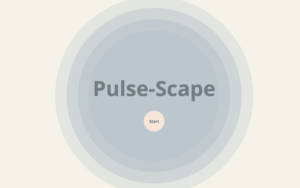
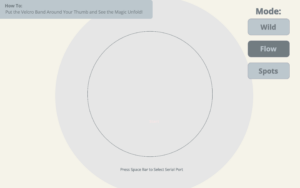
Screenshots of Interface on P5: 

Pulse-Scape in Action

Initial User-Testing:

Show-Case:


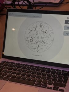
Example of art that Pulse-Scape can generate:

Implementation:

For the project, the main form of interaction design being implemented is pulse detection data from the pulse sensor and the 3 potentiometers that correspond to the R, G, and B values respectively. The potentiometers are responsible for changing the colors of the particles and perlin noise within the circular boundary, helping create a more personalized experience for users. Using data from the pulse sensor, dynamic flow fields appear within a circular boundary, which moves and oscillates based on the value being taken from the pulse sensor. Users can change the style of flow fields, depending on their moods or feelings in the current moment. 

The Arduino component of my final project is mainly responsible for collecting data from the pulse sensor in order to move  it to P5. The first component is for the particles and perlin noise to appear and move based on the data collected from the pulse sensor. The second component is using potentiometers to create a personalized color using specific  amounts of R, G, and B values that users see fit to create a customized and colorful visualization based on pulse sensor data for the users to curate. The Arduino code can be seen below: 

const int pulseSensorPin = A0; //Pulse sensor value connected to A0
const int potPin1 = A1;  // Potentiometer connected to A1
const int potPin2 = A2;  // Potentiometer connected to A2
const int potPin3 = A3;  // Potentiometer connected to A3

// Setup runs once
void setup() {
  Serial.begin(9600);
}

void loop() {
  int pulseSensorValue = analogRead(pulseSensorPin);
  
// Read values from potentiometers and maps it out to the color scale
  int redValue = map(analogRead(potPin1), 0, 1023, 0, 255);
  int greenValue = map(analogRead(potPin2), 0, 1023, 0, 255);
  int blueValue = map(analogRead(potPin3), 0, 1023, 0, 255);


// Send color component values and pulse sensor value to P5
  Serial.print(pulseSensorValue/8);
   Serial.print(',');
  Serial.print(redValue);
  Serial.print(',');
  Serial.print(greenValue);
  Serial.print(',');
  Serial.println(blueValue);

  delay (800);
}


P5, on the other hand, is the main display for my final project. It is where perlin noise and particles are displayed to showcase data from the pulse sensor. It is also in P5 where different modes are available to cater to different style preferences of users in order to personalize their experience. I did this by playing around with the code and multiplying different variables with the pulse sensor value to get different displays. The different styles of art being formulated by the pulse sensor is complimented with the different displays of color within the circle drawn in the center of the canvas. Given the fact that it is the main part of the project and was the part that took me the most time, the aspect of P5 that I am particularly proud of is the display of the particles, which can be found below.

//One of the Three Modes, this is the Flow mode
function mode1(){
 background(245,243,233,5);
  
// Displays pulse sensor value or prompt to select serial port
  if (!serialActive) {
    textStyle(NORMAL);
    strokeWeight(1);
    noStroke();
    textSize(18);
    textFont('Open Sans');
   fill('#727C81');
    text("Press Space Bar to Select Serial Port", windowWidth / 2 + 8 , windowHeight/ 2 + 368); 
  } 
//Display Sensor Value
  else {
    textStyle(NORMAL);
    strokeWeight(1);
    noStroke();
    textSize(18);
    textFont('Open Sans');
    fill('#727C81');
    text('Pulse Sensor Value = ' + str(pulseSensorValue),  windowWidth / 2 + 8 , windowHeight/ 2 + 368); 
  }

//Instruction Header on the Top Left Corner of Canvas
  fill(188, 199, 205);
  rect(-8, 0, 740, 90, 10);
  fill('#727C81');
  textSize(21);
  textStyle(BOLD);
  text('How To:', 65, 35);
  textStyle(NORMAL);
  text('Put the Velcro Band Around Your Thumb and See the Magic Unfold!', 355, 65)
  
// Draws circular boundary for particles to stay within
  stroke('#727C81');
  noFill(); 
  strokeWeight(1);
  ellipse(windowWidth / 2, windowHeight / 2, boundaryRadius * 4); 
  
// Continuously add new particles with random positions within the cirlce
  for (let i = 0; i < 5; i++) {
    particles.push(createVector(random(width), random(height))); 
}
  
// Assigns the current particles to currentParticle variable, this repeats for each particle
  for (let i = particles.length - 1; i >= 0; i--) {
    let currentParticle = particles[i]; 
    
//If pulse sensor value is NOT zero, create flow fields 
  if (pulseSensorValue !== 0) {
    //Calculates perlin noise for the current particles on dispaly
      let perlinNoise = noise(currentParticle.x * noiseScale, currentParticle.y * noiseScale, frameCount * noiseScale); 
    //Maps perlin noise value to angle in order to create some kind of osscilations
      let noiseAngle = TAU * perlinNoise; 
    // Create a movement vector based on Perlin noise angle, scaled by particleSpeed
      let noiseVector = createVector(cos(noiseAngle), sin(noiseAngle)).mult(particleSpeed); 
  // Calculates the center of the canvas for the vectors
      let canvasCenter = createVector(width / 2, height / 2);
  // Calculates the distance between the current particle's postion on the canvas and the center of the canvas
      let distanceToCenter = p5.Vector.dist(currentParticle, canvasCenter); 
  // Creates a vector that points from current particle position to center of the canvas and sets magnitude (length) of vector to 150, which is the boundary radius to effectively scale the vector to be within the circular boundary
      let boundaryVector = p5.Vector.sub(canvasCenter, currentParticle).setMag(boundaryRadius*2); 
 // Move the particle towards the boundary if it's outside, modulate movement with pulse value  
      if (distanceToCenter > boundaryRadius*2) {
        currentParticle.add(boundaryVector.mult(1 + pulseSensorValue)); 
      }
  // Update the position of the current particle by adding the noise-based movement vector
    currentParticle.add(noiseVector); 
  // Remove particles that go off the canvas  
    if (!onCanvas(currentParticle)) {
        particles.splice(i, 1); 
      } 
  //If particles are in the boundary,
    else {
        strokeWeight(2);
        stroke(redValue, greenValue, blueValue); 
      // Draw particle as a point
        point(currentParticle.x, currentParticle.y); 
      }
    }
  }

The main form of communication between Arduino and P5 is unidirectional, meaning that communication comes from only one direction. In my case, data is taken from Arduino and reflected on P5. As mentioned above, the Arduino collects data from both the pulse sensor and 3 potentiometers, which are processed as needed, and then transmitted serially to the computer running P5. This data, once transported  to the computer, P5 receives it, interprets it, and then displays it through particles, oscillations, and perlin noise in the sketch itself. Using this one-way flow of information, the system remains simple but efficient, embodying the concept I initially intended for my final project. 

The aspect of the project that I am particularly proud of is the flow field I created using noise and particles. This is because I had to restudy the presentations and look through youtube videos to understand how to implement the flow fields in the way I envisioned them to be. It was initially quite difficult to implement as I was still a beginner when it came to the technicalities of flow fields, noise, and particles but through practice and trial and error, I was able to overcome this challenge and was able to manipulate the particles and flow fields to be constrained within a circular boundary to create a simple, dynamic, and aesthetically pleasing interface for users to experience. In terms of areas of improvement, I believe that I could have added more interactivity in P5JS to create a more comprehensive interactive experience for users. For example, by adding a feature where particles within the circle will disperse  when users click within the it would add more depth to the interactivity of the experience and make it more engaging for users who are experiencing it. I could have also added some form of wearable device, such as a glove or a bracelet, that the pulse sensor is attached to in order to improve user-experience and better the interactive experience as a whole. This is because it clearly shows users how to navigate the experience with no direct instructions, which is why it creates a more engaging, personal, and interactive experience for users. Reflecting on the process of creating my final project, I am really proud of the outcome and how far I have come with both P5 and Arduino. I am genuinely happy that I was able to create something that combined my interest of bringing out the humanness of human nature, through detecting the heart beat from users’ fingers, and integrating it into a form of technology to create an overall interactive experience for users to engage with. 

I also want to say that I am incredibly proud of everyone and that I am really happy with how far we have all come. Congrats and have a great summer!

With love, Aysha ⋆。°✩


W12- Final Project Draft 1

Concept:

I have always been interested in the complexity of human emotion and humanness in different art forms. For my final project, I have chosen to delve deeper into my interest by exploring the concept of humanness through the integration of technology and art. Central to this exploration is the utilization of a pulse sensor, a device capable of detecting heartbeats in real-time. I intend for the pulse sensor to serve as a bridge between the physical digital digital worlds, which can help me capture the intimate and raw rhythms of the human heart, reflecting the concept I want to bring to life. By using physiological data, I aim to create a dynamic and interactive experience using the p5js canvas as my medium to display it. To add to the interactive and immersive experience I am trying to create, I want to add a piezo buzzer to create noise as the user moves the mouse horizontally across the canvas. These different noises can help cultivate a deeper immersive experience for users. Therefore, the main vision for my project is to craft an immersive experience where users not only witness but engage with the essence of human emotion through visual art, color, and sound. 

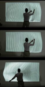
Example-

Like how the person in the image is moving the interactive are piece with his hands, facilitating movement, I want to create a digital form of something similar where users can move their mouse horizontally to create dynamic movement just like in the image.

Design and Description of Arduino and P5 Program:

The Arduino program will mainly be responsible for receiving data from the pulse sensor via serial communication with the P5 program. Meanwhile, the P5 program will create an interactive visualization using the data received from the pulse sensor. The addition of a piezo buzzer adds another layer of sensory engagement, immersing users deeper into the experience. The buzzer will create various noises utilizing the horizontal position of the mouse on the P5 canvas as data to create sound.  By integrating the functionalities of both Arduino and P5, the project creates a holistic and immersive experience that captivates users and invites them to explore the intricate interplay between humanness, technology, art, and sound.


W12- Design Meets Disability

In Design Meets Disability, Graham Pulin delves into the significance of crafting designs with both accessibility and inclusivity in mind. Something Pulin seems to continue to highlight though is the transformative potential of inclusive design in the design world we know of today. Pulin’s emphasis on reframing disability aids as fashion statements, for example, challenges the prolonged societal perception of aid being designed simply for it to be functional. This highlights the impact that design can have on shaping cultural attitudes, particularly towards certain communities, which in this case are those who are classified as people of determination. In my eyes, this perspective showcases the need for designers to push against their own assumptions about certain communities and consider not only the functional purpose of objects those people might need but also the aesthetics and means of personal expression that can come through with these creations. 

This, however, is easier said than done. Designing for disability within a societal context filled with stigmas, biases, and misperceptions makes it incredibly difficult for people to design creations that are complex in terms of aesthetics and functionality. Given this, I believe that the first step to actually being able to design for disability in a way that is void from any biases is to acknowledge one’s own thoughts and how it may impact the way one would design. By actively engaging in understanding the ways one might think about certain communities such as people of determination, designers can gain invaluable insight into the lived experiences and preferences of those within the disability community, ensuring that these designs are reflective of their needs and desires. Actively engaging in a form of human-centered design can lead to not only more effective and sustainable designs but also fosters a sense of empowerment among those they serve, something that many current disability aids lack. It is only by truly rethinking the traditional paradigms and embracing a more human-centered and holistic approach to designing can we celebrate inclusivity and empower those we help through our designs. 

W12- Serial Communication Exercises 1-3

Team Members: Alreem and Aysha:)

Exercise 1- 

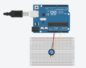
Using a potentiometer, we made an ellipse move left and right on the horizontal axis, ensuring that nothing on the Arduino is controlled by p5.

Schematic

P5js Code

//Variable to declare the ellipse moving acorss the x-axis
let ellipseX;

function setup() {
  //Canvas dimensions
  createCanvas(400, 400);
  //Set text size to 18 pixels
  textSize(18);
  //Initializes ellipse to half the width of the canvas, essentially centers it
  ellipseX = width/2; 
}

function draw() {
  //Sets background to a light purple shade
  background("rgb(185,185,228)");
   // SetS fill color for the ellipse
  fill("rgb(142,142,228)");
  // Sets stroke color/outline for the ellipse
  stroke("rgb(91,91,233)");
  // Draw ellipse at ellipseX position, centered vertically, with a diameter of 120 pixels
  ellipse(ellipseX, height / 2, 120, 120);
  
  // If serial connection is not active, display message to prompt user to select serial port
  if (!serialActive) {
    //Sets fill color to white
    fill('white');
    // Sets stroke color to a gray shade
    stroke('#666666')
     // Display instructions at (15, 30)
    text("Press Space Bar to select Serial Port", 15, 30);
  } 
  // If serial connection is active, display "Connected" message
  else {
    // Display instructions at (15, 30)
    text("Connected", 15, 30);
  }
}

// Function to handle key presses
function keyPressed() {
  // If space bar is pressed, call setUpSerial() function
  if (key == " ") {
    setUpSerial();
  }
}

// Function to read data from the serial port
function readSerial(data) {
  // Check if data is not null
  if (data != null) {
    // Split the received data into an array using comma as delimiter
    let fromArduino = split(trim(data), ",");
    // Map the potentiometer value to adjust the position of the ellipse
    ellipseX = map(int(fromArduino[0]), 0, 1023, 0, width); 
  }
}

Arduino Code

const int potPin = A1;  // Analog pin connected to the potentiometer
void setup() {
  Serial.begin(9600);
}
void loop() {
    int potValue = analogRead(potPin);  // Read the value from the potentiometer
      // Send the potentiometer value to p5.js
      Serial.println(potValue);
}
Exercise 2- 

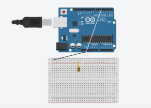
Using a slider, we controlled the LED brightness from p5.

Schematic

P5js Code

// Variable to hold the brightness value
let brightness = 0;
// Variable to hold the slider
let slider;

function setup() {
  //Canvas dimensions
  createCanvas(400, 400);
  // Create slider with range from 0 to 255 and initial value of 100
  slider = createSlider(0, 255, 100);
  // Positions slider horizontally centered and vertically centered
  slider.position(132, height/2);
}

function draw() {
  // Sets background color to a light gray shade
  background('#ADB9C7');
  // Gets  current value of the slider
  let val = slider.value();
  // Updates brightness variable with the slider value
  brightness = val;
  //If brightness is maximum (255), change background color to light blue
  if (brightness == 255) {
    // Changes background color to gold when brightness is max
    background('#DCECFF');  
  }
  
  // If serial connection is not active, display message to prompt user to select serial port
  if (!serialActive) { 
    // Set fill color to blue
    fill('#0876FF');
    // Set stroke color to a light gray shade
    stroke('#B2B2B2');
    // Set text size to 16 pixels
    textSize(16);
    // Display instructions at (20, 30)
    text("Press Space Bar to select Serial Port", 20, 30);
  } 
  // If serial connection is active, display "Connected" message
  else {
    textSize(16);
    // Display instructions at (29, 30)
    text("Connected",29,30);
  }
}

// Function to handle key presses
function keyPressed() {
   // If space bar is pressed, start the serial connection
  if (key == " ") {
    setUpSerial();  
  }
}

// Function to send data to the serial port
function readSerial(data) {
  // Check if data is not null
  if (data != null) {
    
  //Creates a string to send to Arduino with brightness value followed by newline character (HANDSHAKE)
    let sendToArduino = brightness + "\n";
  // Send data to Arduino
    writeSerial(sendToArduino);
  }
}

Arduino Code

// Define the pin for the LED (PWM PIN)
int LED = 5;

void setup() {
  // Set the LED pin as an output
  pinMode(LED, OUTPUT);
  // Start serial communication at 9600 
  Serial.begin(9600);
  
  // Perform initialization handshake
  while (Serial.available() <= 0) {
    // Send a message to indicate initializing connection
    Serial.println("Initializing Connection");  
    // Delay for a short time
    delay(200);               
  }
}

void loop() {
  // Wait for data from p5.js sketch
  while (Serial.available()) {
    // Read the brightness value from serial communication
    int brightness = Serial.parseInt(); 
    // Check if the next character received is a newline character
    if (Serial.read() == '\n') {
      // Set the brightness of the LED using PWM (analogWrite)
      analogWrite(LED, brightness); 
      // Send a message to indicate that LED is turned on
      Serial.println("ON"); 
    }
  }
}
Exercise 3- 

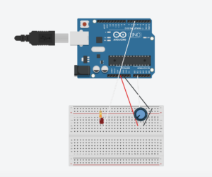
Taking the gravity wind example provided, we made it so that every time the ball bounces and touches the bottom of the canvas, the led lights up and then turns off. We also added a potentiometer in order to control the wind of the ball, helping it move left and right.  

Schematic

P5js Code

// Variables for physics simulation
// Velocity vector
let velocity; 
// Gravity vector
let gravity;
 // Position vector
let position;
// Acceleration vector
let acceleration;
// Wind vector
let wind;
 // Drag coefficient
let drag = 0.99;
// Mass of the ellipse
let mass = 70;

// Flag to control LED based on ball bounce
let ballBouncing = 0;

function setup() {
  //Canvas dimensions
  createCanvas(400, 400);
  // Set text size based on canvas width
  textSize(width/25);

  // Initialize vectors for position, velocity, acceleration, gravity, and wind
  //Creates vector representing the initial position of the ellipse,set to be horizontally centered (width / 2) and positioned at the top of the canvas (0 on the y-axis)
  position = createVector(width / 2, 0);
  // Creates vector representing the initial velocity of the object,horizontal and vertical components are set to 0, so object is at rest
  velocity = createVector(0, 0);
  //Creates vector representing the initial acceleration of the object,horizontal and vertical components are set to 0, so object is at rest
  acceleration = createVector(0, 0);
  //Creates vector representing the gravitational force acting on the object, set to have a vertical component that depends on the mass of the object, stimulating the effect of gravity pulling the object downwards
  gravity = createVector(0, 0.5 * mass);
  //Creates vector representing the force of wind acting on the object, horizontal and vertical components are set to 0, so no wind affecting the object
  wind = createVector(0, 0);
}

function draw() {
  // Set background color
  background(210, 230, 250);

 // If serial connection is not active, display message to prompt user to select serial port
  if (!serialActive) {
    // Display instructions at (20, 30)
    text("Press Space Bar to select Serial Port", 20, 30);
  } 
  else {
    // Apply forces (gravity and wind)
    applyForce(wind);
    applyForce(gravity);
     // Update position
    // Updates the velocity of the object by adding the current acceleration to it
    velocity.add(acceleration);
    //Multiplies the velocity vector by the drag coefficient, reducing its magnitude and stimulating air resistance
    velocity.mult(drag);
    //Updates the position of the object by adding the current velocity vector to it, helps move ellipse based on velocity
    position.add(velocity);
    //Resets acceleration to 0
    acceleration.mult(0);
   
 // Check boundaries for right and left movement
    //If condition to check if the x-coordinate of the object is exceeding the right boundary of the canvas
    if (position.x > width - mass / 2) {
      //If object's x-coordinate exceeds the right boundary, set the x-coordinate of the object's position to exactly width - mass / 2, placing the object right at the right boundary
      position.x = width - mass / 2;
      // Reverses velocity when hitting right boundary by multiplying it by -0.9, applying a dampening effect to the velocity
      velocity.x *= -0.9; 
    } 
   //Condition to check if the x-coordinate of the object is exceeding the left boundary of the canvas
    else if (position.x < mass / 2) {
      //If object's x-coordinate exceeds the left boundary, set the x-coordinate of the object's position to exactly width - mass / 2, placing the object right at the right boundary
      position.x = mass / 2;
      // Reverses velocity when hitting left boundary by multiplying it by -0.9, applying a dampening effect to the velocity
      velocity.x *= -0.9; 
    }

    // Draw the bouncing ball
    ellipse(position.x, position.y, mass, mass);
    
    //Check boundary for vertical movement (bottom of the canvas)
    if (position.y > height - mass / 2) {
      //Set the y-coordinate of the object's position so that the bottom of the object aligns with the bottom edge of the canvas
      position.y = height - mass / 2;
       // Reverses velocity when hitting bottom boundary by multiplying it by -0.9, applying a dampening effect to the velocity
      velocity.y *= -0.9; 
      //Sets flag to indicate ball bouncing
      ballBouncing = 1;
    } 
    //Resets flag if ball is not bouncing
    else {
      ballBouncing = 0;
    }
  }
}

// Function to handle key presses
function keyPressed() {
   // If space bar is pressed, start the serial connection
  if (key == " ") {
    setUpSerial();
  } 
  // Change mass and reset ball position when Enter key is pressed
  else if (key == "ENTER") {
    // Randomly set the mass of the object within the range of 15 to 80
    mass = random(15, 80);
    // Set the initial y-coordinate of the object's position above the canvas to simulate it entering the scene
    position.y = -mass;
    // Reset the velocity of the object to zero to ensure it starts from rest
    velocity.mult(0);
  }
}

// Function to send data to the serial port
function readSerial(data) {
  // Check if data is not null
  if (data != null) {
// Parse incoming data
    let fromArduino = split(trim(data), ",");
    // If it's the accurate length, then proceed
    if (fromArduino.length == 1) {
      // Store values here
       // Extract potentiometer value and map it to wind force
      let potentiometerValue = int(fromArduino[0]);
      //Mapping pontentiometer value to wind force
      wind.x = map(potentiometerValue, 0, 1023, -1, 1);
    }
   //Creates a string to send to Arduino with brightness value followed by newline character (HANDSHAKE)
    let sendToArduino = ballBouncing + "\n";
    writeSerial(sendToArduino);
  }
}

// Function to apply force to the object
function applyForce(force) {
  // Newton's 2nd law: F = M * A or A = F / M
  // Calculate the force acting on the object by dividing the applied force vector by the mass of the object
  let f = p5.Vector.div(force, mass);
  // Add the resulting force vector to the object's acceleration to calculate its new acceleration
  acceleration.add(f);
}

Arduino Code

// Define the pin for the LED
int ledPin = 5;
// Define the pin for the potentiometer
const int potPin = A1;

void setup() {
  // Start serial communication at 9600 
  Serial.begin(9600);
  
  // Set the built-in LED pin as an output
  pinMode(LED_BUILTIN, OUTPUT);
  // Set the LED pin as an output
  pinMode(ledPin, OUTPUT);
  // Set the potentiometer pin as an input
  pinMode(potPin, INPUT);

  // Start the handshake
  while (Serial.available() <= 0) {
    // Blink the built-in LED while waiting for serial data
    digitalWrite(LED_BUILTIN, HIGH);
    // Send a starting message to the p5.js sketch
    Serial.println("0,0");
    // Delay for a short time
    delay(300);
    // Turn off the built-in LED
    digitalWrite(LED_BUILTIN, LOW);
    // Delay for a short time
    delay(50);
  }
}

void loop() {
  // Wait for data from p5.js sketch
  while (Serial.available()) {
    // Turn on the built-in LED while receiving data
    digitalWrite(LED_BUILTIN, HIGH);
    // Turn off the LED connected to ledPin
    digitalWrite(ledPin, LOW);
    // Read the integer value representing whether the ball is bouncing
    int ballBouncing = Serial.parseInt();
    
    // Check if the next character received is a newline character
    if (Serial.read() == '\n') {
      // Read the value from the potentiometer
      int potPinValue = analogRead(potPin);
      // Short delay to stabilize the reading
      delay(5);
      // Send the potentiometer value to the p5.js sketch
      Serial.println(potPinValue);
    }

    // Set LED brightness based on whether the ball is bouncing
    if (ballBouncing == 1) {
      digitalWrite(ledPin, HIGH); // Turn on the LED
    } else {
      digitalWrite(ledPin, LOW); // Turn off the LED
    }
  }
  // Turn off the built-in LED
  digitalWrite(LED_BUILTIN, LOW);
}


W12- Final Project Idea

As I was brainstorming potential ideas for my final project, I realized that a key concept I want to focus on is the essence of being human, specifically touching upon the elements that make us human such as emotion, heartbeat, facial expressions, etc. The reason why I want to focus on this specific topic is because I am intrigued by the ways in which humans and computers are able to interact with one another, and what the implications of such an interaction might be. Although this project will not lead to wide implications for the world of human-computer interaction, I believe that simply understanding how such an interaction can work is in of itself important. Therefore, it is through actually engaging with such interactions that we can understand the different ways in which the users and computers can interact to create a system/ illustration that exhibits data of some kind. 

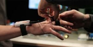
After brainstorming, I tried to find inspiration by looking up youtube videos related to the concept of humanness. A common project I noticed was the interactive glove, in which users are able to control certain projects with the movement of their hands. This, in my eyes, is a good utilization of humanness. It embraces a critical part of human nature and combines it with computer interaction. A good example that I found of this can be seen below: 

However, I know I do not want to do a project that has to do with building an interactive glove. Instead, I want to create a project in which the human heart beat is detected in order to create fast or slow paced interactive art. I want to create an even more comprehensive user-experience, which is why I want to add the option of changing the color of the interactive art displayed after detecting the user’s heartbeat. Although I do not know the intricate details of the project yet, I do know that committing to such a project will allow me to explore my interest in human computer interaction and utilize it to create personal interactive art for users.

W11 Assignment- Alreem and Aysha’s Musical Instrument 🎶

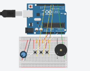
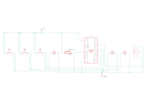
For this week’s assignment, Alreem and I decided to create a simple musical instrument using buttons, potentiometer, and a piezo buzzer. Using these 3 items as our project’s main components allows us to showcase our concept of creative simplicity, in which we emphasize simple design but use our creativity to create some form of abstract output.  We wanted to utilize this concept as our main aim for this project which is to build an instrument that is not only easy to understand from both a schematic and user-design perspective, but also produce a diverse range of musical tones and rhythms. The musical instrument generates tunes when users press the designated buttons on the breadboard, allowing them to craft a unique tune of their own. The potentiometer offers users the ability to adjust the frequency of the tunes produced by the buttons, further enhancing their ability to personalize their musical experience. The hands-on and interactive approach to this project not only promotes personal creativity but also encourages users to experiment with different tone combinations, all within the framework of a simple and user-friendly design.

Below you can find the project’s diagrams:

Circuit Diagram

Schematic Diagram
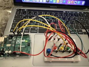
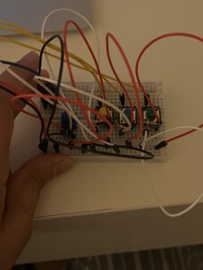
After finalizing our schematic diagram, we started to build the project using the Arduino. The full list of the components used is as follows: 12 wires, 3 330 resistors, 3 buttons, potentiometer, and a piezo buzzer.  These components are what helped ensure that the tunes are heard when the buttons are pressed and adjusted when the potentiometer is turned. You can see the fully complete project below: 


When coding for this project, we struggled a bit with getting the certain tunes to be the way we wanted them. It was only when we tried and tested several different tunes for the different buttons did we get the rhythm/tunes we wanted for our final project. Therefore, that is the part of the code that we are most proud, which can be seen below:

#include "pitches.h"

// New melodies:
//For Button 1
int melodyPart1[] = {
  NOTE_C4, NOTE_E4, NOTE_G4
};

//For Button 2
int melodyPart2[] = {
  NOTE_A4, NOTE_C5, NOTE_E5
};

//For Button 3
int melodyPart3[] = {
  NOTE_G5, NOTE_E5
};

// Note durations: 4 = quarter note
int noteDurations[] = {
  4, 4, 4
};

//Function to play the tune on the buzzer, melody[] = array that containes the notes that need to be played, melodyLength = the number of notes in the melody array, tempoDelay = the delay (in milliseconds) between each note
void playMelody(int melody[], int melodyLength, int tempoDelay) {
// Initializes thisNote to 0, continues looping as long as thisNote is less than melodyLength, and increments thisNote after each loop
  for (int thisNote = 0; thisNote < melodyLength; thisNote++) {
//Calculates the duration of the current note
    int noteDuration = 1000 / noteDurations[thisNote];
//Plays the current note on the buzzer connected to buzzerPin
    tone(buzzerPin, melody[thisNote], noteDuration);

//Calculates the duration of the pause between the current note and the next note, adds 30% longer pause to the duration
    int pauseBetweenNotes = noteDuration * 1.30;
//Determine how long to wait before playing the next note
    delay(tempoDelay); // Use tempoDelay instead of fixed pauseBetweenNotes

//Stops the buzzer sound from playing the assigned tune by turning off 
    noTone(buzzerPin);
  }
}

Overall, this project was an enlightening experience for both Alreem and I. It gave us the opportunity to combine our previous knowledge of working with circuits and programming to create something that is not only functional to users but also quite enjoyable to use. The project’s emphasis on simplicity resonated with us a lot as we wanted the project to speak for itself, which is why we are more than happy to see how by just using a few basic components, we could create a musical instrument of sorts that is capable of producing various tunes. That being said, we still feel like there are areas of improvement for our project. Next time, it would be interesting to explore adding additional features or potentially modes to our makeshift instruments, such as having more piezo buzzers in order for more than one tune to be played. Doing this might help enhance user-experience, creating a more well-rounded project. That being said, we are proud of how far we have come! Despite minor challenges we faced, we were able to collaborate together and successfully create a musical instrument that engages with the users in a personal way. 

W11- Reading Reflection

Reading Bret Victor’s rant about the future of interaction design was eye opening to say the least. We often think that the top innovative ideas are those that revolve around advanced touch screens and improving computer interfaces such as the newly released Apple Vision Pro, which combines new technologies that utilizes 3D camera technology to act as a “spatial computer.” These are what people consider innovative and the future of interaction design. However, what if we go back to the basics in regards to interaction? What if we deeply think about how we interact with things? What allows us to interact with things? Victor proposes that the central component of the future of interaction design is hands. Hands? Yes, you heard it right! When I initially heard his proposition, I was perplexed. How could our hands be the future of innovation and interaction design? 

As I reflected on Victor’s insights, I realized that the central component of innovation and interaction does not lie in the fancy touch screens we so happen to develop. In fact, the central components for such things are found on our bodies. In most cases, it is always our hands that allow for the concept of interaction to take place. Without them, I would go as far as to say the idea of interaction as we know of today might not exist. From the responses article, many were skeptical about the topic and say that hands cannot be the ultimate future for interaction design, that it would make us move a step backwards in the industry. Well, Victor and I choose to disagree.

 If we go back in time and look at different forms of interaction design, nearly all projects require some form of interaction using the human hand, whether that is tying a shoe lace or even just moving objects in a virtual world. Even today, the most prominent forms of interaction design usually enforce human interaction using none other than our hands. Therefore, how can we claim that the human hand is not the future of interaction design when nearly all innovative projects use it as the main source of interaction? We cannot! This is why I truly believe that instead of pushing our humanity away in design, we should recognize that it is our hands that are the beginning and future of interaction design. Cool-looking interfaces and spatial computers are undeniably innovative creations but they are not the answers to our interactive future; they are merely tools that reflect our innate human essence, showcasing the power our hands can play in interaction design.

W10- Dual Lighting System Using Digital and Analog Sensors

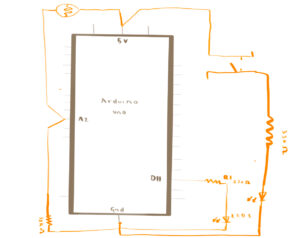
As I am still experimenting with physical computing and coding for Arduino, I tried to emphasize simplicity for this week’s assignment. The concept for this week’s assignment is a simple lighting system using both digital and analog sensors. This lighting system has two LEDs, one attached to a manual system while the other an automatic one. This gives users the freedom to either choose to use only one light system or both. I was inspired to create this dual lighting system because I often feel like versatility in lighting is important not only to give a space more dimension but to also make our lives easier. With such a system, users are able to ensure that they have the right lighting for the circumstance they are in but also have the freedom to control it the way they see fit. Below you can find the schematic diagram of the system I created:

(warning, schematic diagram might not be comprehendible!)

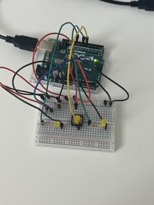
After finalizing the schematic, I began building the actual system using the Arduino uno. The components used in this assignment were 11 wires, 2 LEDs, one button, one photo-resistor, 1 10K resistors, and 3 330 resistors. These components helped to create an efficient dual lighting system that helps users have a good balance between manual control and automatic adjustment of the lighting. I pinned the 5v and the ground to the positive and negative ends of the bread board to act as a “main ground” for the rest of the circuits on the bread board. For the button part of the circuit, I placed one end of the red wire to connect to the positive end of the board and one end of the 330 resistor. The other end of the 330 resistor is placed at the negative end of the bread board to ground it. The wire attached to 5v is attached to one end of the button, while the other end of the button is attached to pin 7. This wire is connected to another 330 resistor, which is attached to the LED A that is used for the “manual” system. The other end of LED A is grounded in the negative end of the bread board. For the photo-resistor, one end of it is attached to the positive end of the bread board where 5 voltage is. The other end of the photo-resistor is a wire that is attached to A1, which is an analog pin. That wire is connected to a 330 resistor. One side of the resistor connects to the wire that is connected to the negative end of the bread board where it is grounded. For LED B, which is the automatic part of the circuit, one side is connected to the negative end of the bread board where it is grounded and the other side is connected to a 330 resistor. The other end of the 330 resistor is connected to a wire, which is attached to pin 11. This makes the full manual and automatic light system. Below, you can find an image of the built system based off of the schematic diagram:


Programming the LEDs to function as intended required code for each. The first LED was programmed to turn on and remain on when the button was pressed and off and stay off when the button was pressed again, representing the digital sensor aspect of the system. The second LED was designed to activate and deactivate automatically in response to the light levels detected by the photo-resistor, which represents the analog sensor aspect of the system.  While the automatic adjustments based on the light levels might appear to be the most complex part of the system, it was actually the digital control of the first LED that presented the most challenges. I had to review class materials several times, go over examples, and watch youtube videos to get to the vision I wanted to have for this system. The youtube video that ultimately helped me to get to the vision I wanted was Robotics Back-End’s Arduino- Turn LED On and Off With Push Button video, which has been cited  at the bottom of this blog post. Therefore, that is one part of code that I am particularly proud of. 

void loop() {
//BUTTON
int buttonState = digitalRead (7);
// Check if enough time has passed since the last button state change
if (millis() - lastTimeButtonStateChanged >= debounceDuration){
   // Check if the button state has changed
  if (buttonState != lastButtonState){
    // Update the last time the button state changed
    lastTimeButtonStateChanged = millis();
    lastButtonState = buttonState;

    // Toggle the LED state when the button is pressed
    if (buttonState == LOW){ //If button is not pressed
      if (ledState == HIGH){ //and LED is on,
        ledState = LOW; //make LED turn on
      } else{ //if button is pressed,
        ledState = HIGH; //Make the LED turn on
      }
       // Update the LED controlled by the button
      digitalWrite(8, ledState);
   }
  }
 }
}

As you can see, the code corresponding to the button is intricate, utilizing a lot of ‘if’ statements to achieve the desired  on and off effect when the button is pressed. You can see this and the whole system in action below:  

In terms of improvements, I would have definitely liked to have only one LED to make it as similar to a typical light system as possible. I initially thought of coding one LED to have both the manual and automatic light systems but I, unfortunately, was not able to get it to function the way I wanted it to. Therefore, that is something I would like to improve on for the future. However, I have to say even with the countless days spent on this assignment, I genuinely enjoyed getting to the final product and seeing my vision come to life some way or another. As I mentioned earlier in this blog post, I was still adjusting to physical computing and using Arduino, which is why I wanted to create something simple. Creating this lighting system, although simple, was a big step into seeing not only the ways in which you can use physical computing components to create things that you envision but it has also allowed me to see the ways in which it can be used to fix real world problems. Even if this was obvious to me, it was only when I started to create things of my own did I see the potential and reach of physical computing in helping fix many of the problems people are facing today, which is something I am glad to have seen for myself. 

References: 

[Robotics Back-End]. (2022, February 28). Arduino – Turn LED On and Off With Push Button [Video]. Youtube. https://www.youtube.com/watch?v=ZoaUlquC6x8

W10 Reading Reflection

As a creative, I often see art as a form of self expression, a statement made by an artist to convey a message to an audience. Providing detailed interpretations of specific works, you could describe what each element, color, composition of the work means and how the audience should interpret it. That was the way I was taught to go about my practice, which I was also going to bring in when creating interactive projects for this class. However after reading Tigoe’s post about physical computing, I saw my perspective shift. Tigoe makes the point that interactive art is actually not about making a statement but about how the project is able to serve as an instrument or environment that invites the audience to engage , interact, and interpret it. This forced me to see art as a point of communication and not simply a form of expression. It opened my eyes to the reality that my role as a designer, creative or artist is to simply set the stage, provide the context, and then take a step back. It is only when this is done will the true beauty of art, but more specifically, interactive art, lie. Therefore, when creating one should try to prioritize setting the stage for dialogue, creating an environment that invites the audience to interpret and interact with the art as they wish. 

Reading Tigoe’s second blog post about physical computing’s greatest hits and misses allowed me to see my new found understanding in action. Tigoe showcased different projects from faculty and students alike that showcase the essence of interactive art that he preached about in the first blog I mentioned. What I found really interesting is that all of these projects, although they have instructions, give freedom for the user to engage with the project in the way they seem fit. For example, the Gloves project allows for users to make a rhythm by moving your hands or fingers in a particular way. Even if everyone engages with it, the rhythms they create and the way they decide to go about using the project varies greatly based on individual movements, interpretations, and interaction. To me, this reaffirms the idea that interactive art is never the same for everyone and that it thrives on two things: collaboration and personal interpretation. If these foundational principles are not at the forefront during ideation and creation stages of interactive projects, we are left questioning: is it truly interactive, or is it merely a static piece of art masquerading as interactive?


W9 Assignment- Magical Book Switch ✨🔮🃏

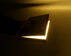
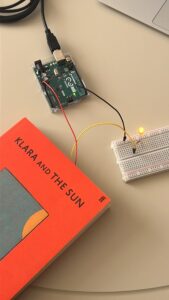
When we were given this assignment, I was conflicted with how I was supposed to go about it. I knew I wanted to create something simple, not overly complex due to the fact that I was still getting used to using the different elements of physical computing we learned in class. After days of brainstorming, I came up with the idea of a “magical” book switch, in which the LED lights up when the book is shut and turns off when opened. This idea came about when I was reading a book called Klara and the Sun, which prompted me to reminisce about similar books and movies that I used read and watch growing up. A concept that kept reoccurring in all these books and movies is the glowing book, which you can see below:

This concept is the main inspiration behind my switch assignment. It is through allowing the closed book to light the LED up and turn it off when it is opened that this assignment resembles the concept I initially Imagine.

Progress and Assembly

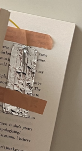
I created a circuit using a yellow LED, wire, a book and aluminium foil, all of which are interconnected with one another. I first started off by connecting the red wire to the 5v pin (I will elaborate on its significance in a bit) and the black wire to the ground pin on the arduino board. I then connected the black wire to the positive part of the breadboard, which is the same part where the LED’s negative pole sits. The LED’s positive pole is on the terminal strip of the breadboard. On the same line as the LED’s positive pole, I placed a 330-ohm resistor to help reduce the flow of the circuit as a whole to ensure that the current passing through does so in safe limits. On the other end of the resistor, I placed another wire to be attached to the book. However, to ensure that the LED actually lights up, I needed conductive material. In the case of this assignment, I used aluminium foil. I created 2 rectangle with my foil and made sure that there was space to attach the wires. I made each wire have their own individual piece of foil. I then taped the foil covered wires to corresponding pages of books.

You can see this below:

The primary goal of this setup was to make the LED light up when both wires touch one another when the book is closed.

In the image below, you can see the full circuit in action:


Video of Circuit: 

https://youtube.com/shorts/PoatHJr2I3I

Reflections

I really enjoyed the process of building and putting this assignment together. I genuinely believe that it helped me get more practice in using the concepts we learned this past week. It allowed me to see how I can take the things we learned and apply it to something from my imagination. I definitely feel more comfortable using the arduino board and its different elements. In terms of improvements, I would have loved to add some element of interactivity. Maybe something that would allow the user to engage with the circuit in order to make the LED light up. Other than that, I actually am happy with the final result and cannot wait to use the board to create more elaborative and complex circuits!