Final Project: Germa-phone

Concept:

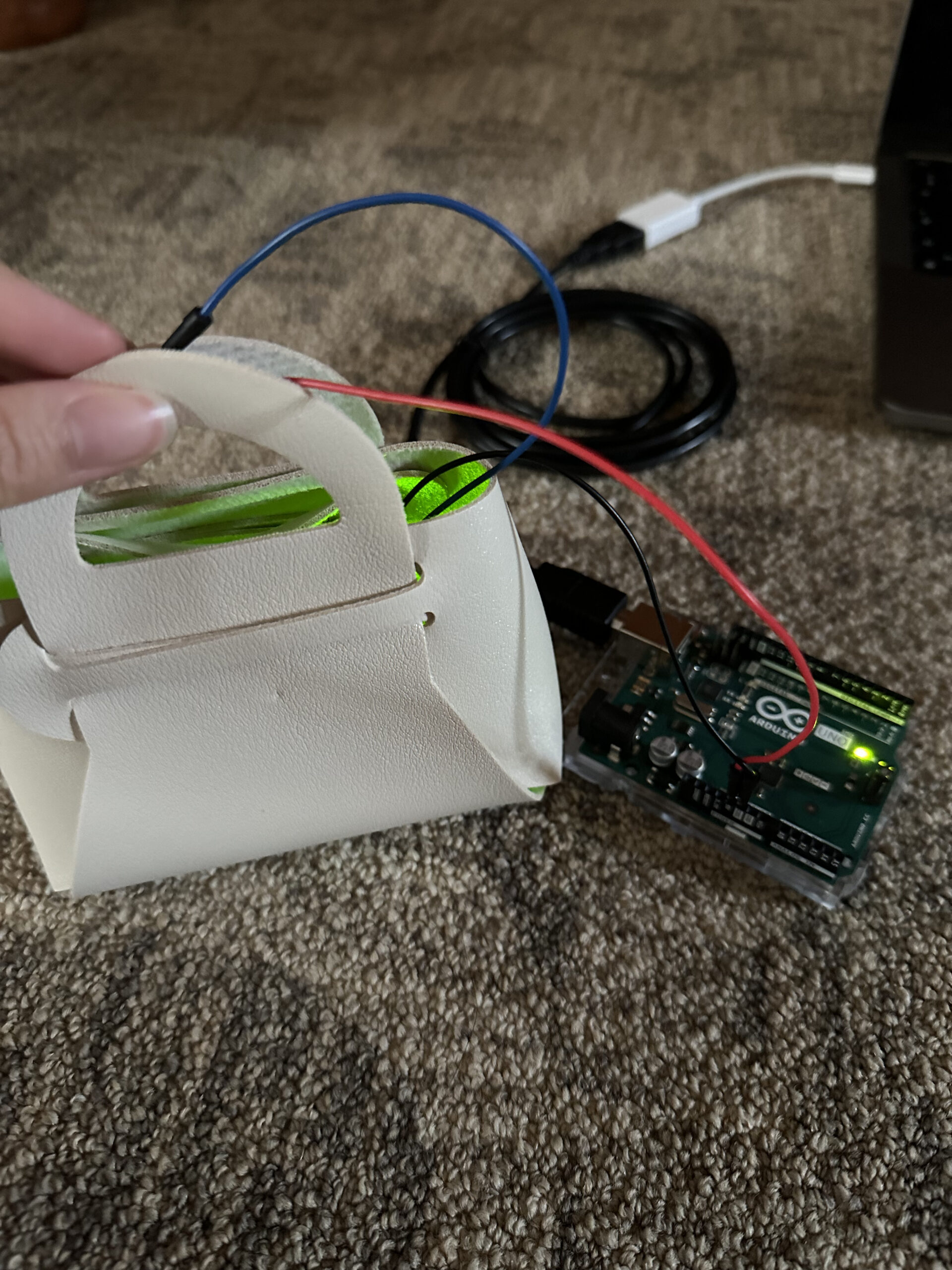
My final project was more of a product rather than a game to play. It is very simple to use where you just click on buttons from the computer to have your phone cleaned. I decided to do this project because our phones are in our hands most of the time, and it is necessary for it to be clean as many germs could be spread through the phone.

P5.js:

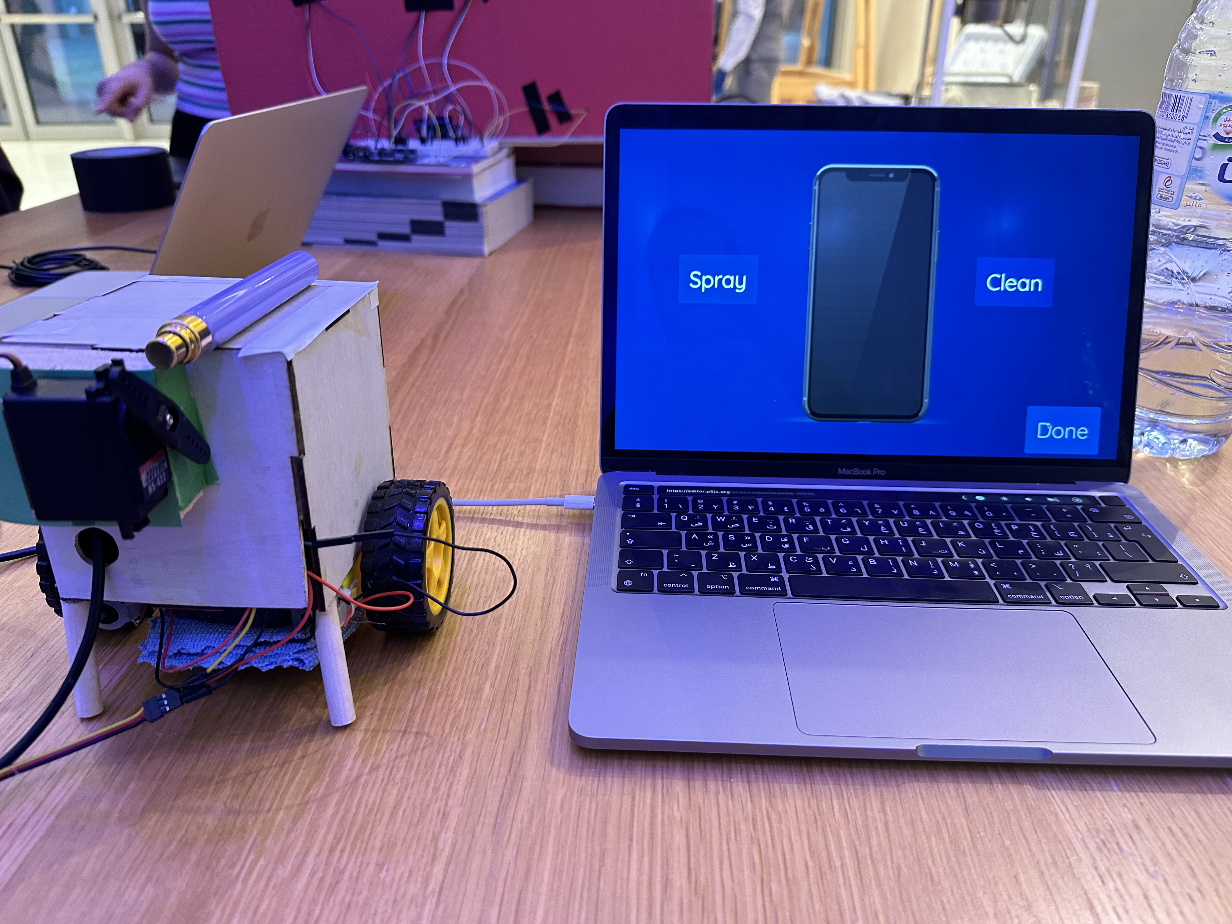
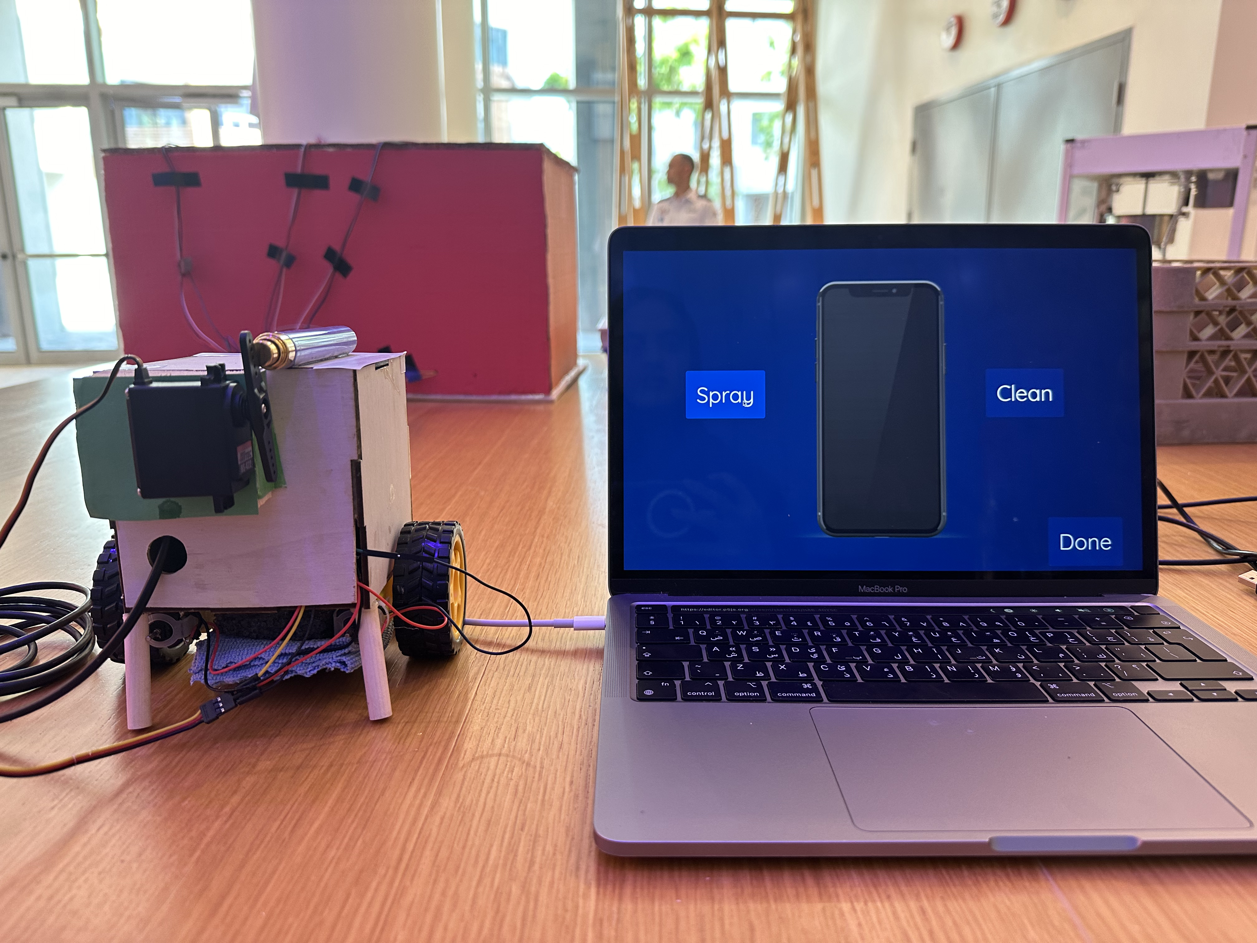
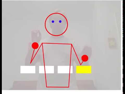
In p5.js, I first created a main page with some instructions, from there you can click on the space button to connect the serial port and proceed to the main page to clean your phone.

Cover Page
Main page


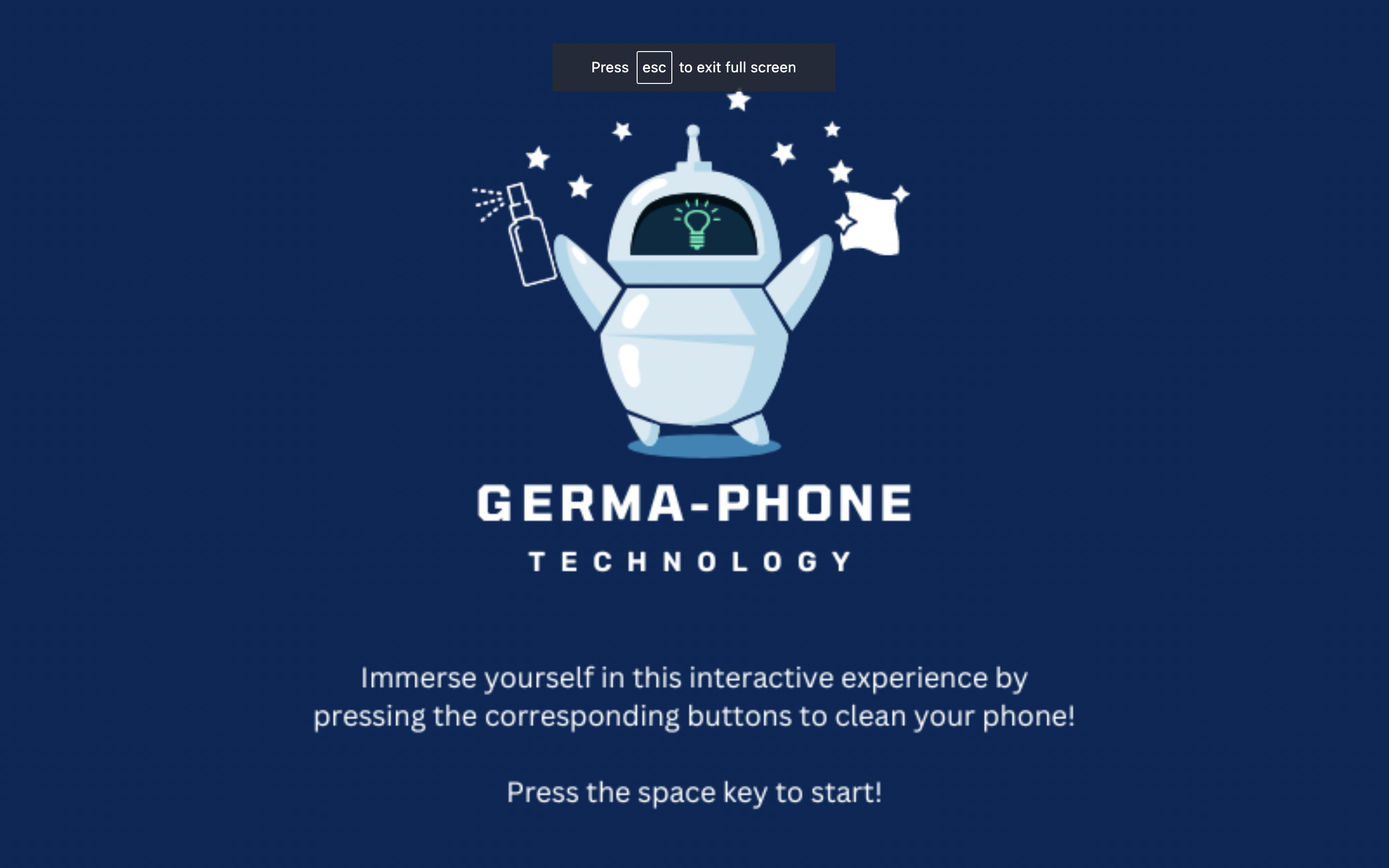
(To open the following in full screen, press the “f” key.)
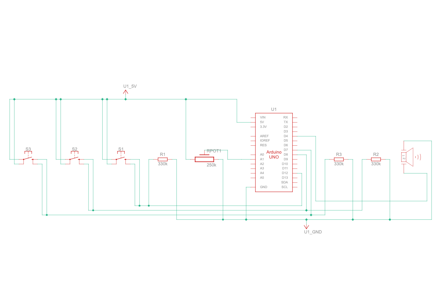
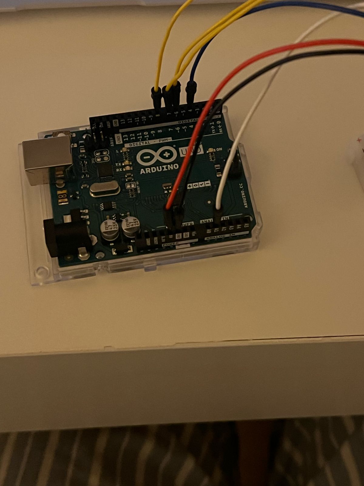
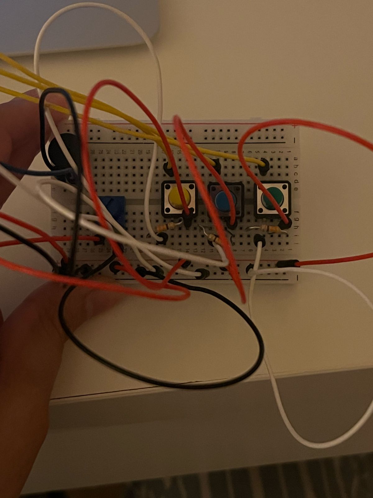
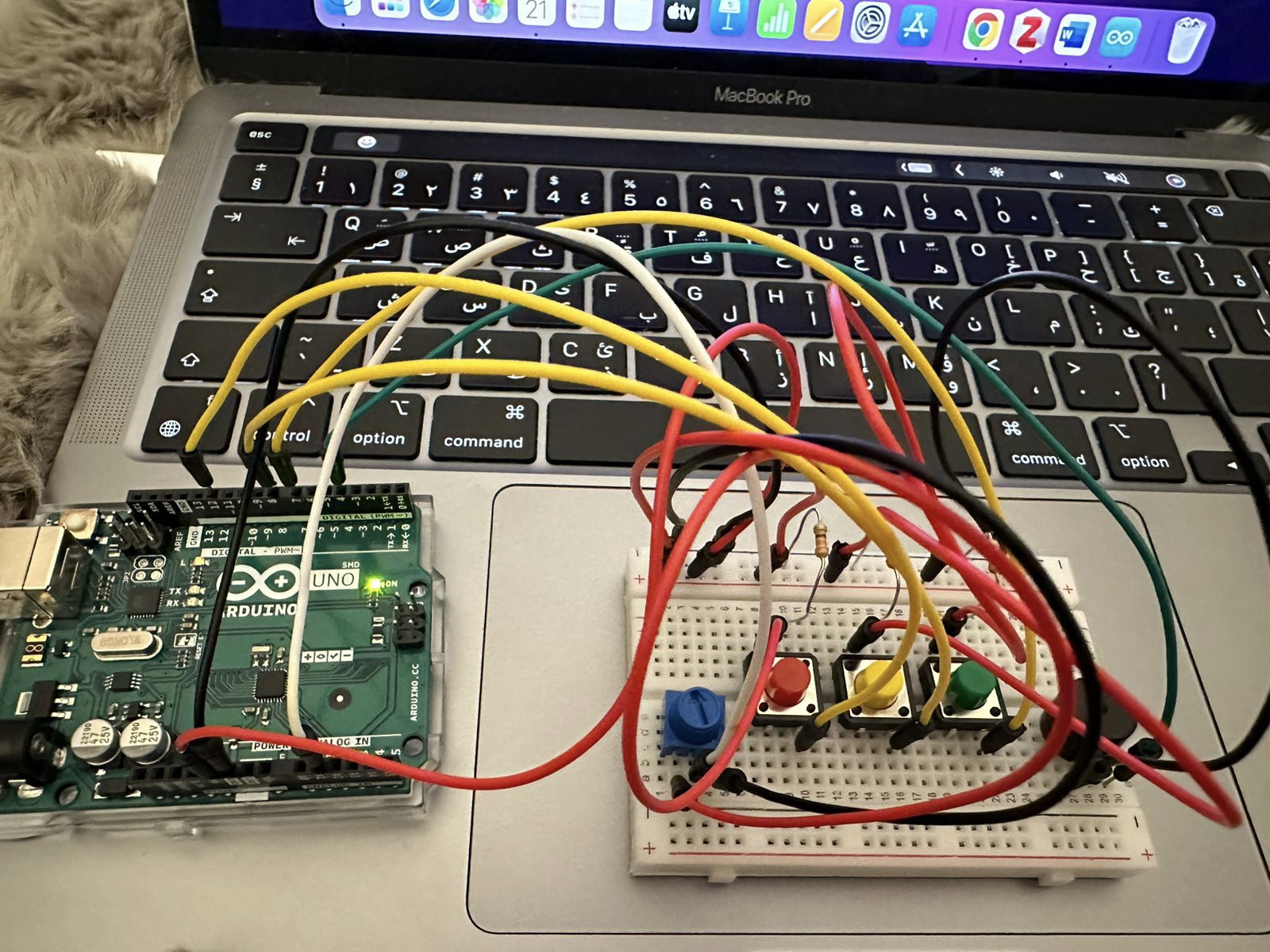
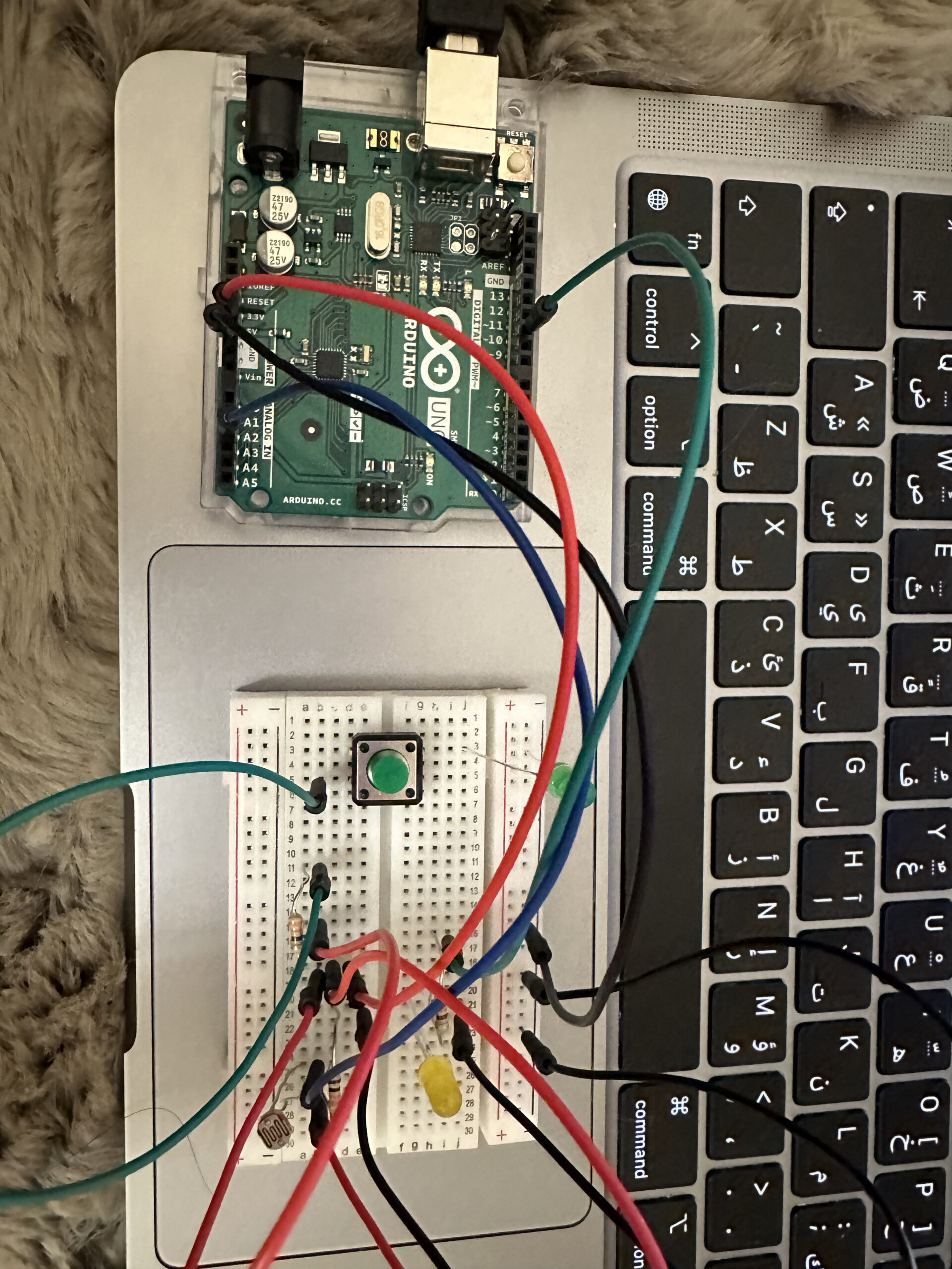
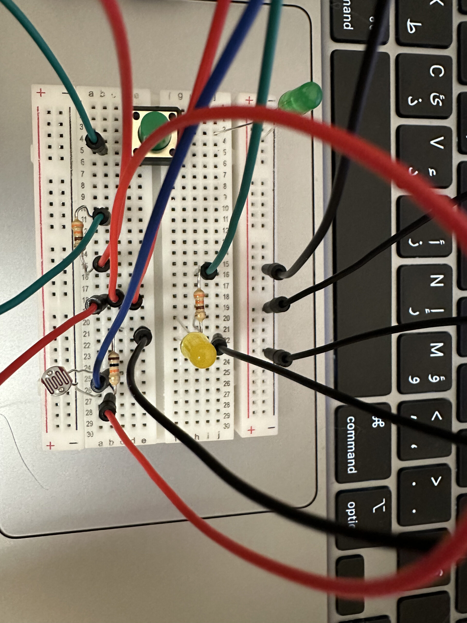
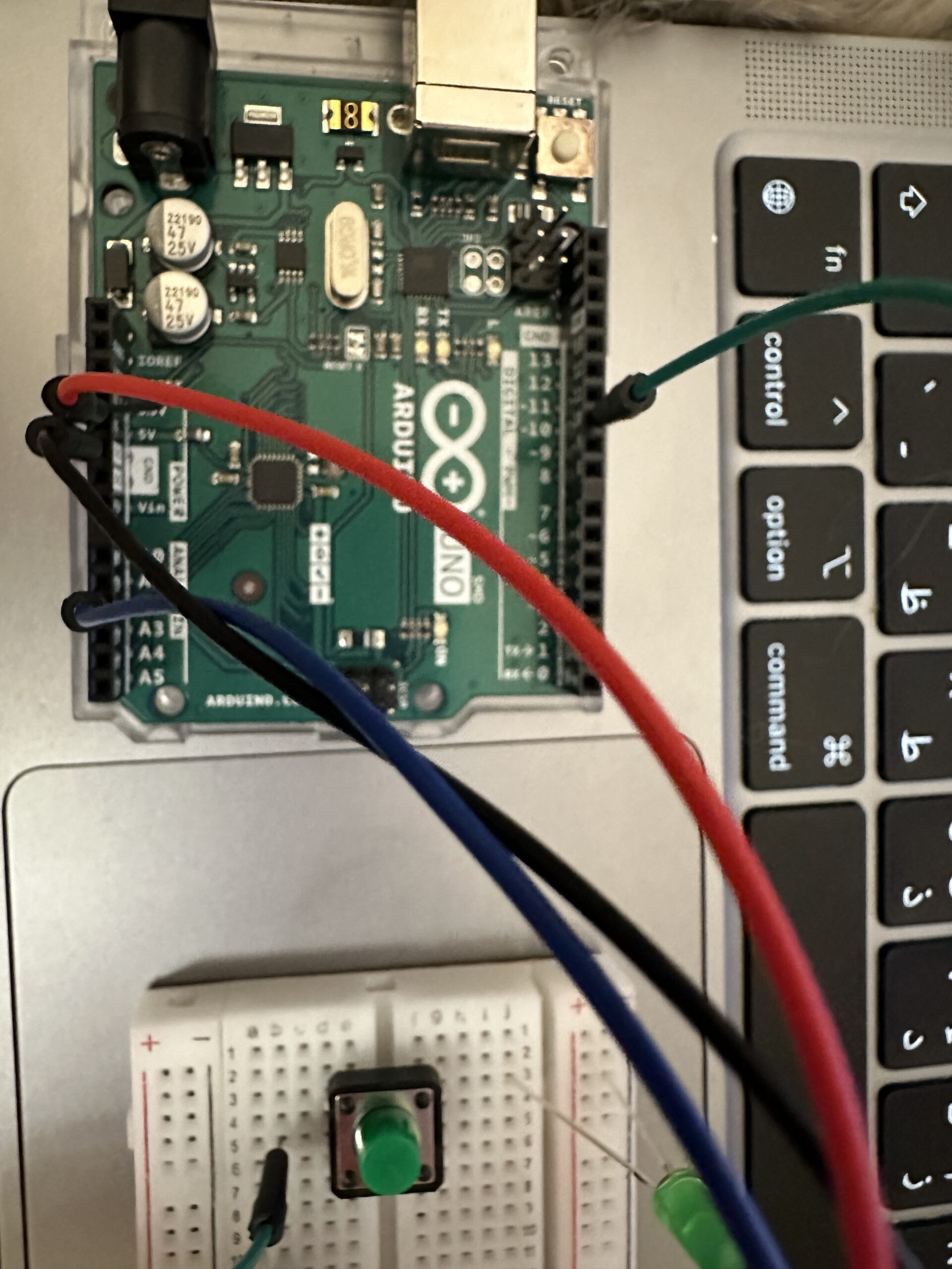
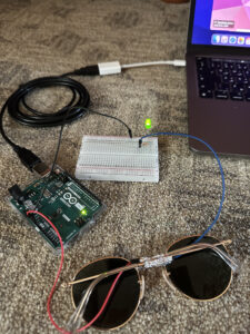
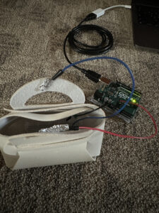
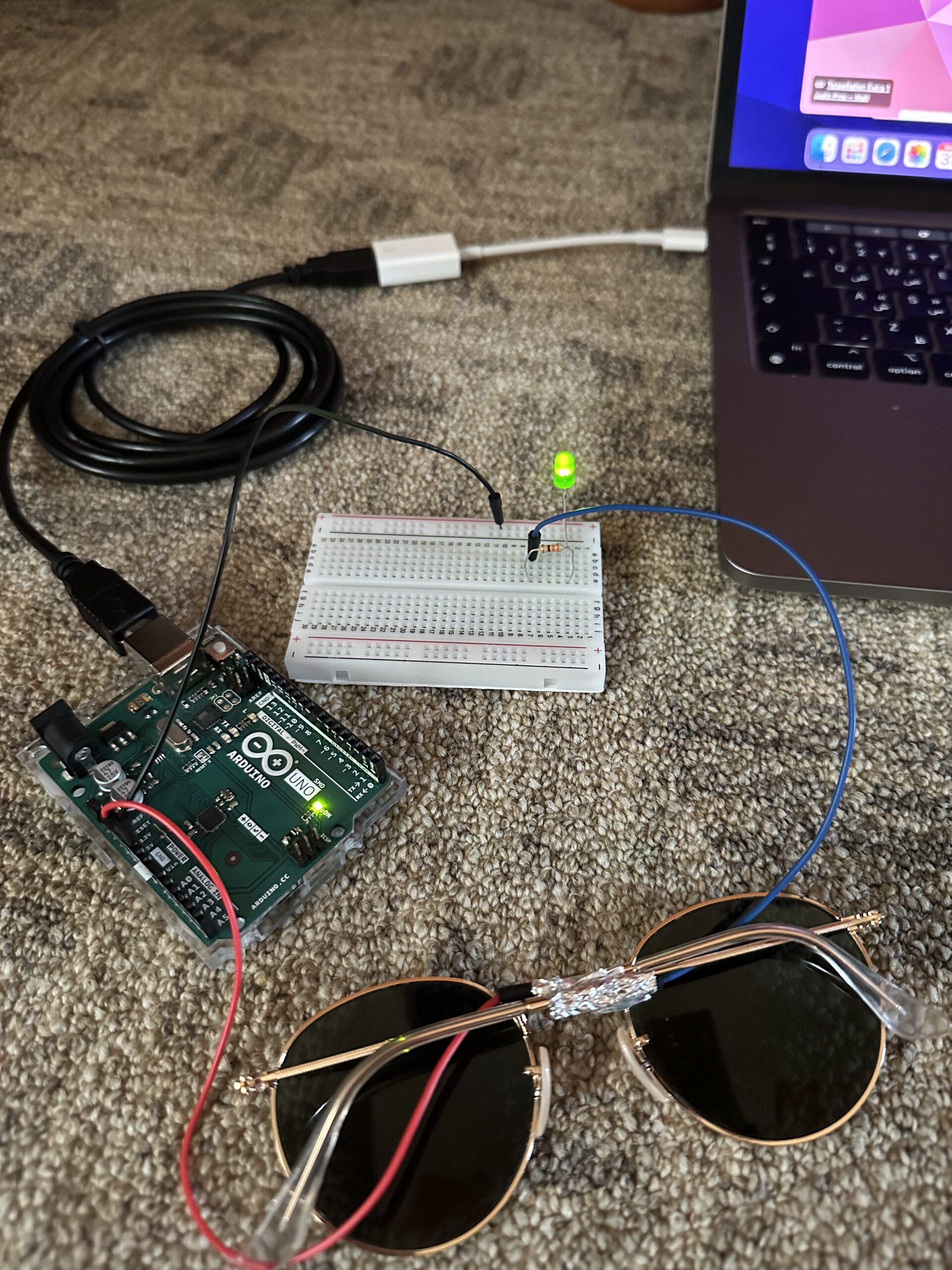
Arduino:

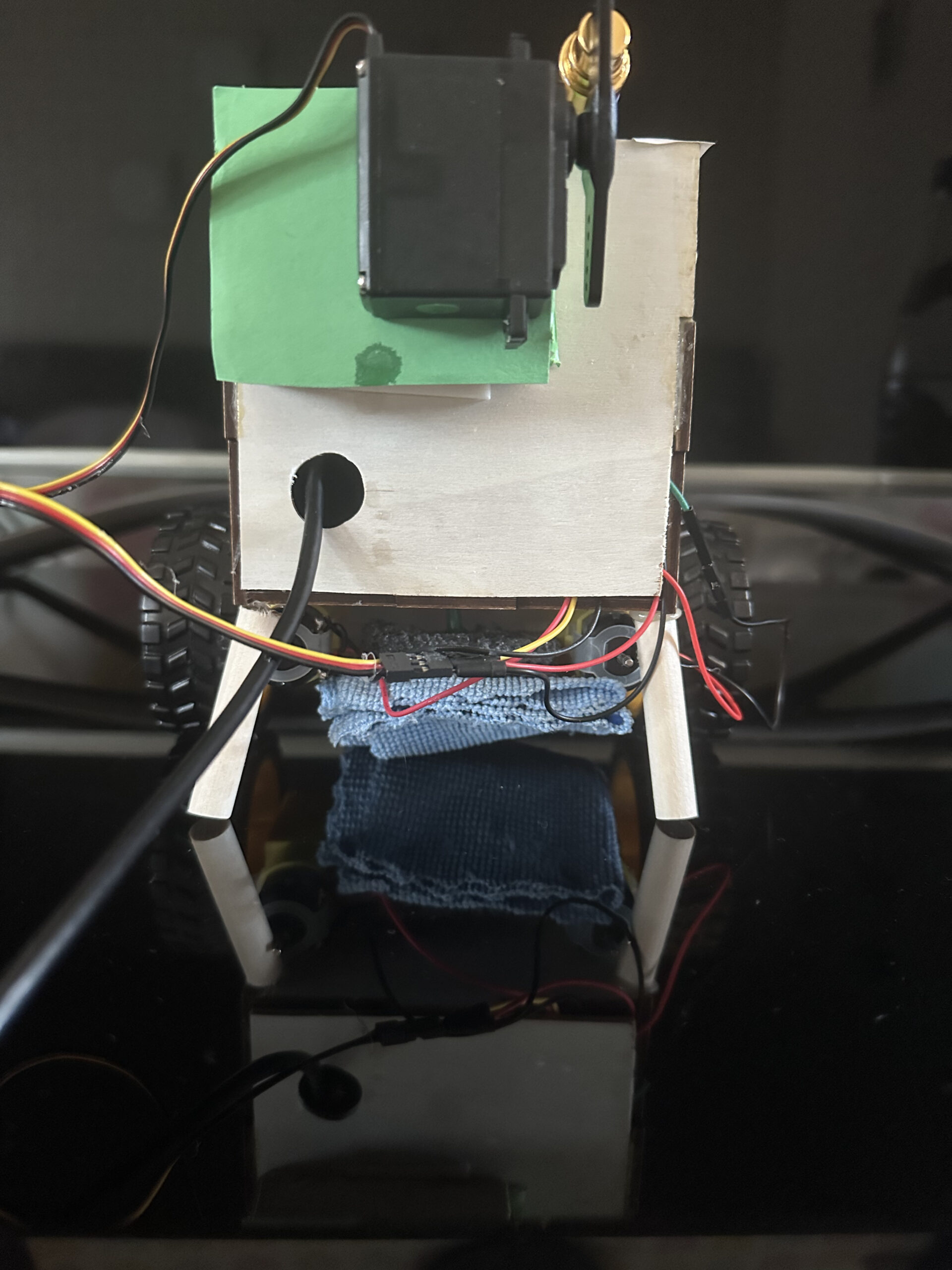
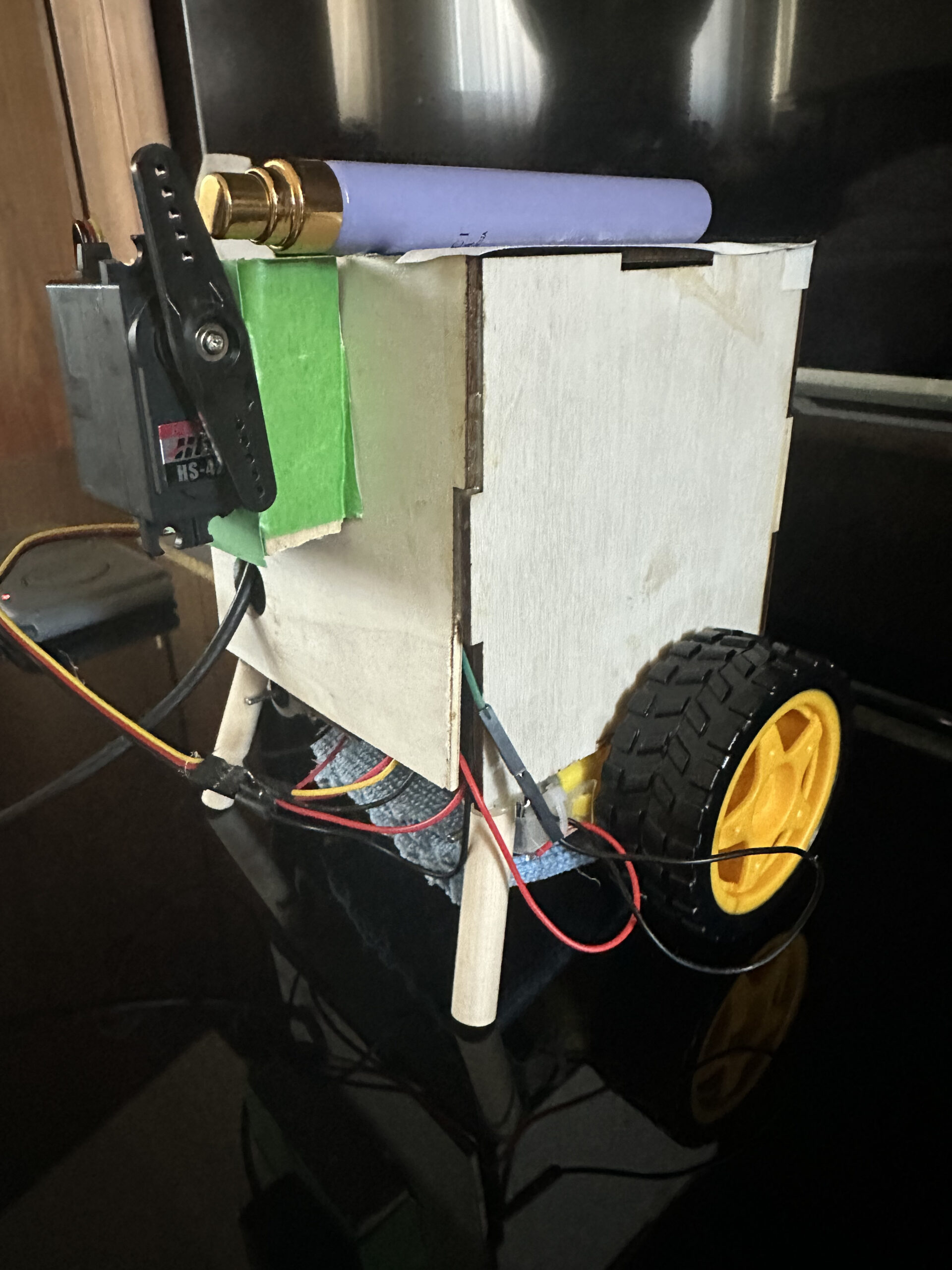
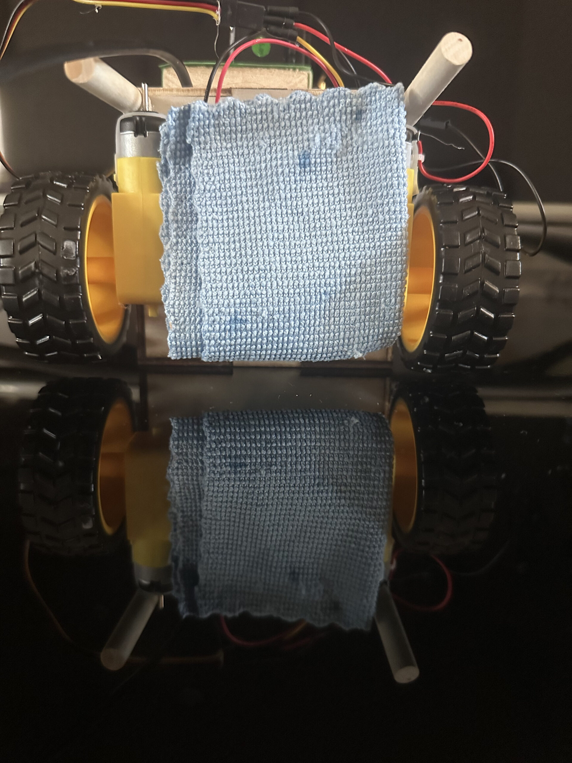
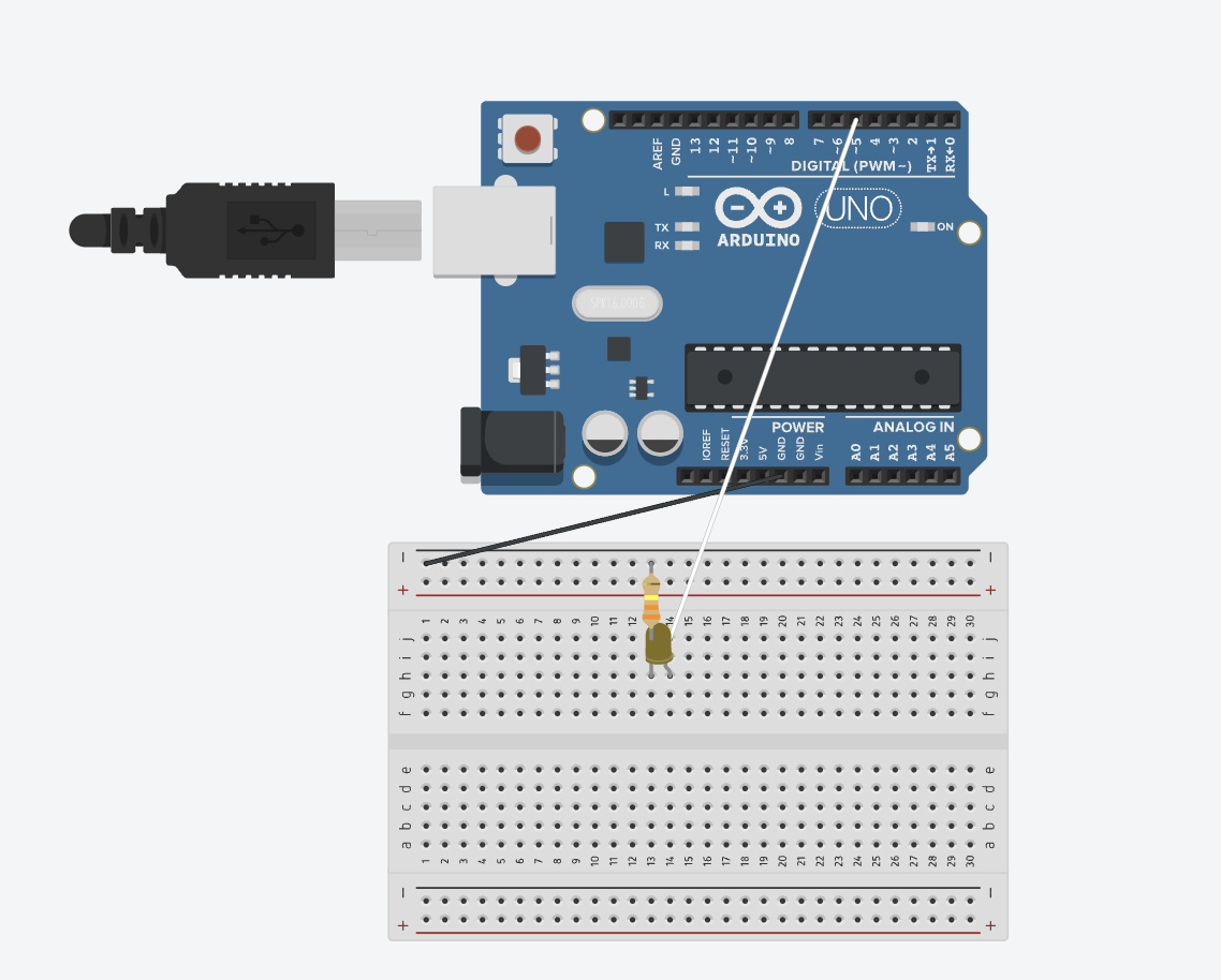
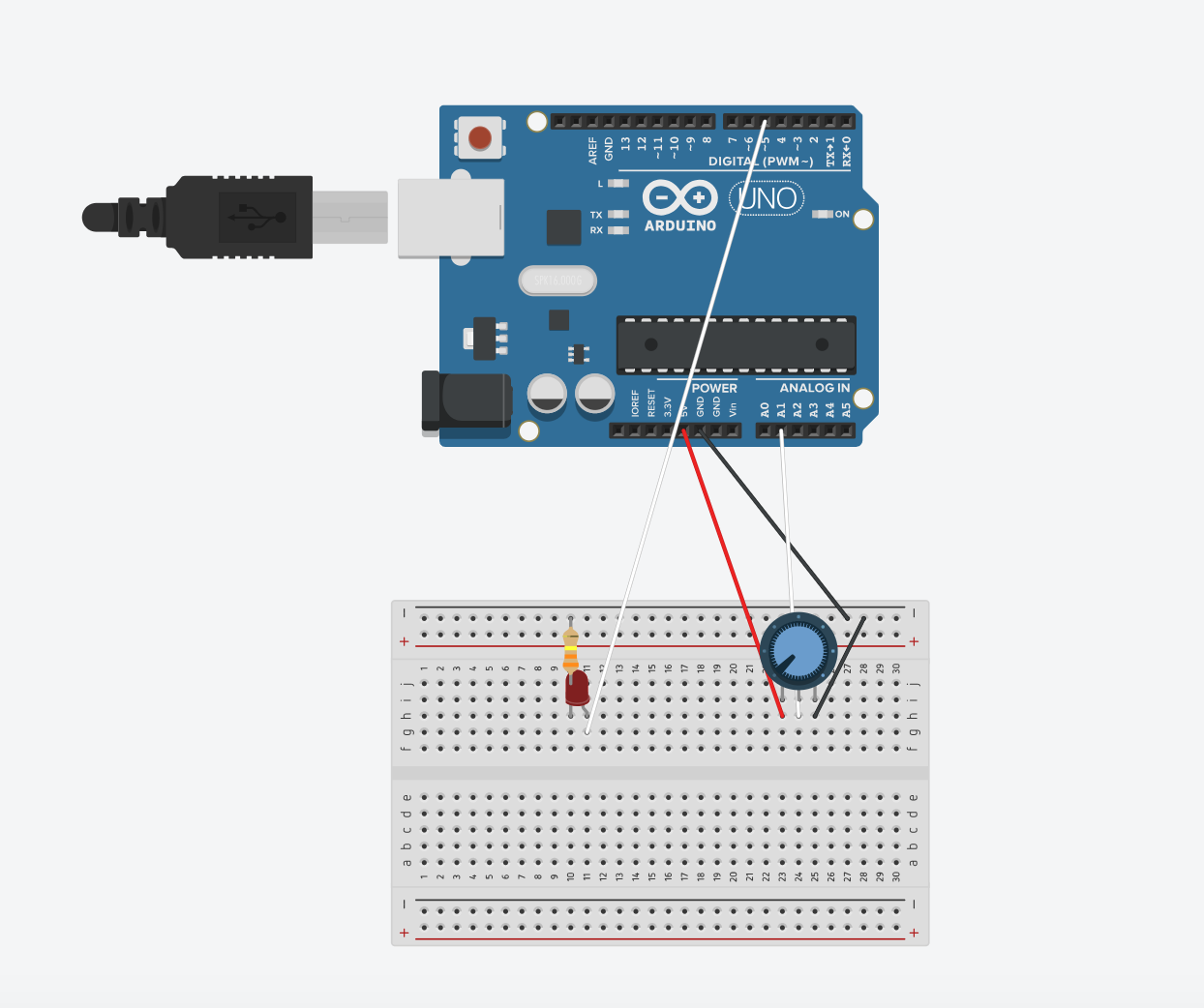
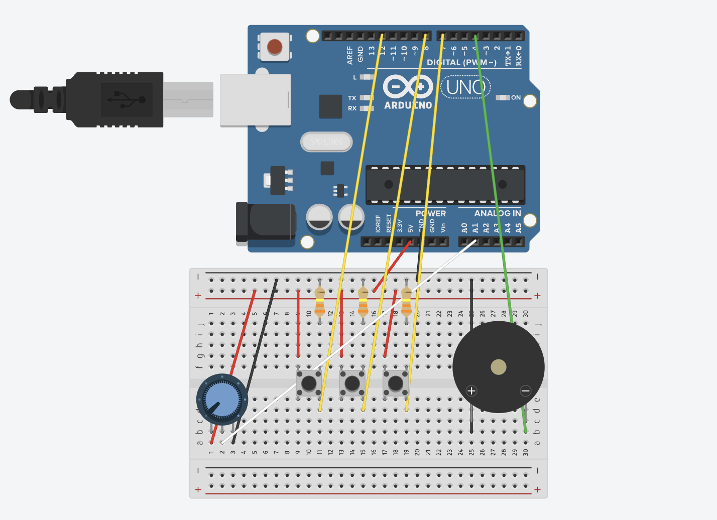
For the arduino part, I laser cut a 5in box to put the arduino, breadboards,  and batteries inside. Outside the box, I had a servo motor controlling a spray and dc motors controlling two wheels . Under the box, there was a small wiper that dried out the spray while the wheels are moving.


User testing:

IMG_5132

Serial Communication: 

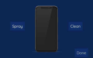
For the serial communication part, it was a one way communication from p5.js to arduino. When the spray button is clicked, it activates the servo motor to spray the phone. When the clean button is clicked, it activates the two dc motors and moves the wheels to wipe the phone.

Challenges & Code I am most proud of:

The most challenging part was trying to include a ultrasonic distance sensor to detect the phone. However, I realized that it is not an important aspect of the project so I decided to focus on the servo and dc motors only.

It was very tricky to code the two motors according to the angle of the box and in a particular speed. That is the part of code I am most proud of.

Arduino:

   // Activate servo motion
 for (pos = 120; pos <= 180; pos += 1) { // goes from 0 degrees to 180 degrees
    // in steps of 1 degree
    myservo.write(pos);              // tell servo to go to position in variable 'pos'
    delay(4);                       // waits 15 ms for the servo to reach the position
  }
  for (pos = 180; pos >= 120; pos -= 1) { // goes from 180 degrees to 0 degrees
    myservo.write(pos);              // tell servo to go to position in variable 'pos'
    delay(4);                       // waits 15 ms for the servo to reach the position
  }

// Activate dc motion
forwardDirection = !forwardDirection;

    // Set direction for motor A
        if (forwardDirection) {
          digitalWrite(ain1Pin, HIGH);
          digitalWrite(ain2Pin, LOW);
        } 
        else {
          digitalWrite(ain1Pin, LOW);
          digitalWrite(ain2Pin, HIGH);
        }

    // Set direction for motor B
        if (!forwardDirection) {
          digitalWrite(bin1Pin, HIGH);
          digitalWrite(bin2Pin, LOW);
        } 
        else {
          digitalWrite(bin1Pin, LOW);
          digitalWrite(bin2Pin, HIGH);
        }

        // Turn both motors at this speed
        analogWrite(pwmAPin, 90);
        analogWrite(pwmBPin, 90);

        // Delay for a second
        delay(1000);

        // Slow down both motors
        Serial.println("slowing down");
        int speed = 100;
        while (speed--) {
          analogWrite(pwmAPin, speed);
          analogWrite(pwmBPin, speed);
          delay(100);
  }

P5.js:

function startSpraying() {
  spray = 1;
  clean = 0;
  // Send "1" to Arduino to activate spray
  
    //////////////////////////////////
    //SEND TO ARDUINO HERE (handshake)
    //////////////////////////////////
  
  let sendToArduino = "1" + "\n"; 
  writeSerial(sendToArduino);
  drawDots();
}

function startCleaning() {
  clean = 0;
  spray = 1;
  image(phone, 0, 0, windowWidth, windowHeight, 0, 0, phone.width, phone.height, CONTAIN);
  
  // Send "0" to Arduino to activate clean
  
    //////////////////////////////////
    //SEND TO ARDUINO HERE (handshake)
    //////////////////////////////////
  
  let sendToArduino = "0" + "\n"; 
  writeSerial(sendToArduino);
}

IM showcase & Future Improvements:

IMG_5124

IMG_5120

During the IM showcase, I got a lot of constructive feedback from faculty and students. I got a suggestion to include a sensor that detects the corners of the phone so that the wheels stop moving when it reaches the end of the phone. Someone also said that it would be more convenient if it was a little smaller, especially if they were to use it as a product at home. Another suggestion was to make it resizable or adjustable according to the person’s phone. These are all very interesting approaches I could take if I were to improve this project.

From my side, I would want to improve the design and aesthetics of the physical product and include a bigger spray so it would be more effective.

For now, I am glad that this idea worked to begin with as I was worried that the servo motor would not be strong enough to spray the phone, but it worked!

Resources:

  • Canva (for the p5.js interface)
  • Arduino IDE built-in Examples

Week 12: Design meets disability

I really enjoyed this reading as it gave me a new insight on these products. When we think of discretion in relation to fashion, like the author mentioned, it is a bit tricky to design products for disabilities. There is always a doubt of whether the product should be designed “invisibly” or more as fashion wear. When it is designed to be unseen, it seems more like the disability is to be ashamed of.

In general, having products with good design makes it more likely that the person would enjoy using it. I also found it very interesting the idea of designing unique pieces rather than designing one thing for everyone. Even for people with disabilities, there should be a diversity of designs for a product which should also be something that makes them feel good.

Week 12: Serial Communication

For this week’s assignment, Aysha and I worked on three different exercises that focused on serial communication.

Exercise 1: Moving p5.js ball with potentiometer

p5.js code:

//Variable to declare the ellipse moving acorss the x-axis
let ellipseX;

function setup() {
  //Canvas dimensions
  createCanvas(400, 400);
  //Set text size to 18 pixels
  textSize(18);
  //Initializes ellipse to half the width of the canvas, essentially centers it
  ellipseX = width/2; 
}

function draw() {
  //Sets background to a light purple shade
  background("rgb(185,185,228)");
   // SetS fill color for the ellipse
  fill("rgb(142,142,228)");
  // Sets stroke color/outline for the ellipse
  stroke("rgb(91,91,233)");
  // Draw ellipse at ellipseX position, centered vertically, with a diameter of 120 pixels
  ellipse(ellipseX, height / 2, 120, 120);
  
  // If serial connection is not active, display message to prompt user to select serial port
  if (!serialActive) {
    //Sets fill color to white
    fill('white');
    // Sets stroke color to a gray shade
    stroke('#666666')
     // Display instructions at (15, 30)
    text("Press Space Bar to select Serial Port", 15, 30);
  } 
  // If serial connection is active, display "Connected" message
  else {
    // Display instructions at (15, 30)
    text("Connected", 15, 30);
  }
}

// Function to handle key presses
function keyPressed() {
  // If space bar is pressed, call setUpSerial() function
  if (key == " ") {
    setUpSerial();
  }
}

// Function to read data from the serial port
function readSerial(data) {
  // Check if data is not null
  if (data != null) {
    // Split the received data into an array using comma as delimiter
    let fromArduino = split(trim(data), ",");
    // Map the potentiometer value to adjust the position of the ellipse
    ellipseX = map(int(fromArduino[0]), 0, 1023, 0, width); 
  }
}


Arduino Code:

const int potPin = A1;  // Analog pin connected to the potentiometer
void setup() {
  Serial.begin(9600);
}
void loop() {
    int potValue = analogRead(potPin);  // Read the value from the potentiometer
      // Send the potentiometer value to p5.js
      Serial.println(potValue);
}


Exercise 2: Controlling LED with p5.js slider

p5.js code:

// Variable to hold the brightness value
let brightness = 0;
// Variable to hold the slider
let slider;

function setup() {
  //Canvas dimensions
  createCanvas(400, 400);
  // Create slider with range from 0 to 255 and initial value of 100
  slider = createSlider(0, 255, 100);
  // Positions slider horizontally centered and vertically centered
  slider.position(132, height/2);
}

function draw() {
  // Sets background color to a light gray shade
  background('#ADB9C7');
  // Gets  current value of the slider
  let val = slider.value();
  // Updates brightness variable with the slider value
  brightness = val;
  //If brightness is maximum (255), change background color to light blue
  if (brightness == 255) {
    // Changes background color to gold when brightness is max
    background('#DCECFF');  
  }
  
  // If serial connection is not active, display message to prompt user to select serial port
  if (!serialActive) { 
    // Set fill color to blue
    fill('#0876FF');
    // Set stroke color to a light gray shade
    stroke('#B2B2B2');
    // Set text size to 16 pixels
    textSize(16);
    // Display instructions at (20, 30)
    text("Press Space Bar to select Serial Port", 20, 30);
  } 
  // If serial connection is active, display "Connected" message
  else {
    textSize(16);
    // Display instructions at (29, 30)
    text("Connected",29,30);
  }
}

// Function to handle key presses
function keyPressed() {
   // If space bar is pressed, start the serial connection
  if (key == " ") {
    setUpSerial();  
  }
}

// Function to send data to the serial port
function readSerial(data) {
  // Check if data is not null
  if (data != null) {
    
  //Creates a string to send to Arduino with brightness value followed by newline character (HANDSHAKE)
    let sendToArduino = brightness + "\n";
  // Send data to Arduino
    writeSerial(sendToArduino);
  }
}

Arduino code:

int LED = 5; //PWM PIN
void setup() {
  pinMode(LED, OUTPUT);
  Serial.begin(9600);
  
  
  // initializing handshake
  while (Serial.available() <= 0) {
    Serial.println("Initializing Connection");  
    delay(200);               // wait 1/2 second
  }
}
void loop() {
  // wait for data to load from p5 before continuing code
  while (Serial.available()) {
    int brightness = Serial.parseInt(); 
    if (Serial.read() == '\n') {
      analogWrite(LED, brightness); // turn on LED and adjusts brightness
      Serial.println("ON"); 
    }
  }
}


Exercise 3: Blink LED with bouncing ball and move wind with potentiometer

p5.js code:

let velocity;
let gravity;
let position;
let acceleration;
let wind;
let drag = 0.99;
let mass = 70;

// ball bounce check to control LED
let ballBouncing = 0;

function setup() {
  createCanvas(400, 400);
  textSize(width/25);

  position = createVector(width / 2, 0);
  velocity = createVector(0, 0);
  acceleration = createVector(0, 0);
  gravity = createVector(0, 0.5 * mass);
  wind = createVector(0, 0);
}

function draw() {
  background(210, 230, 250);

  if (!serialActive) {
    text("Press Space Bar to select Serial Port", 20, 30);
  } else {
    applyForce(wind);
    applyForce(gravity);
    velocity.add(acceleration);
    velocity.mult(drag);
    position.add(velocity);
    acceleration.mult(0);
   
 // Check boundaries for right and left movement
    if (position.x > width - mass / 2) {
      position.x = width - mass / 2;
      velocity.x *= -0.9; // Reverse velocity when hitting right boundary
    } else if (position.x < mass / 2) {
      position.x = mass / 2;
      velocity.x *= -0.9; // Reverse velocity when hitting boundary
    }

    ellipse(position.x, position.y, mass, mass);
    if (position.y > height - mass / 2) {
      velocity.y *= -0.9; // A little dampening when hitting the bottom
      position.y = height - mass / 2;
      ballBouncing = 1;
    } else {
      ballBouncing = 0;
    }
  }
}

function keyPressed() {
  if (key == " ") {
    // to start serial connection
    setUpSerial();
  } else if (key == "ENTER") {
    mass = random(15, 80);
    position.y = -mass;
    velocity.mult(0);
  }
}

function readSerial(data) {
  if (data != null) {
    // make sure there is a message and split it
    let fromArduino = split(trim(data), ",");
    // if it's the right length, then proceed
    if (fromArduino.length == 1) {
      // only store values here

      let potentiometerValue = int(fromArduino[0]);
      wind.x = map(potentiometerValue, 0, 1023, -1, 1);
    }

// ARDUINO HANDSHAKE
   
    let sendToArduino = ballBouncing + "\n";
    writeSerial(sendToArduino);
  }
}

function applyForce(force) {
  // Newton's 2nd law: F = M * A
  // or A = F / M
  let f = p5.Vector.div(force, mass);
  acceleration.add(f);
}

Arduino code:

//int ledPin = 5;
//const int potPin=A1;

//void setup() {
  // Start serial communication so we can send data
  // over the USB connection to our p5js sketch
  //Serial.begin(9600);

  //pinMode(LED_BUILTIN, OUTPUT);

  //pinMode(ledPin, OUTPUT);
  //pinMode(potPin, INPUT);


  // start the handshake
  //while (Serial.available() <= 0) {
    //digitalWrite(LED_BUILTIN, HIGH); // on/blink while waiting for serial data
    //Serial.println("0,0"); // send a starting message
    //delay(300);            // wait 1/3 second
    //digitalWrite(LED_BUILTIN, LOW);
    //delay(50);
  //}
//}

//void loop() {
  // wait for data from p5 before doing something
  //while (Serial.available()) {
    //digitalWrite(LED_BUILTIN, HIGH); // led on while receiving data
   //digitalWrite(ledPin, LOW);
   //int ballBouncing =Serial.parseInt();
   
    //if (Serial.read() == '\n') {
    
    //int potPinValue = analogRead(potPin);      delay(5);
      
      //Serial.println(potPinValue);
    //}
  
// Set LED brightness based on whether the ball is bouncing
    //if (ballBouncing == 1) {
      //digitalWrite(ledPin, HIGH);
    //} else {
      //digitalWrite(ledPin, LOW);
    //}
  //}
  //digitalWrite(LED_BUILTIN, LOW);
//}


Final project proposal

Idea:

My final project idea is to make a robotic car that acts as a phone cleaner. The spray would be lying somewhere on top of the car and the mini towel would be somewhere under the wheels in which the car can slide over the phone and wipe it. To control this, the user has to use the buttons on p5.js.

Arduino:

  • Distance sensor to sense if the phone is available.
  • Servo motor for the screen spray.
  • Wheels for the car to move. (x2 or x4)

P5.js:

  • Click button to control spray.
  • Click button and Up and Down keys to control car.

Communications:

At first, the screen on p5.js will ask for the user to insert their phone in front of the car. Once it is detected by the distance sensor, it will send a signal to p5.js and the screen will display a phone with two buttons. The first button will have a spray icon. When it is clicked, it will send a signal to the servo motor and spray the phone. Therefore, it will show a sprayed phone on the screen. The second button will have a wiping icon. When it is clicked, it will allow the user to move the car by clicking the up and down buttons. This way, the car will only move vertically. It will show the phone being dried on the screen while it is wiping.

Final Project Idea

For my final project, my main focus is on p5.js and using posenet from ml5. I want to allow the user to be able to draw in the air by using their right hand as a brush. For the Arduino part, I will be adding different colored buttons to change the color of the ink in p5.js. I also want to add a potentiometer to control the opacity of the color. In addition to that, I might add a piezo buzzer and change the sound according to the position of their hand, something like the photo shown below.

ml5.js posenet xylophone

gikfun 12 x 12 x 7,3 mm taktile Tact Push Button Momentary SMD PCB Schalter mit Cap für Arduino (25 Stück) ae1027 : Amazon.de: Gewerbe, Industrie & Wissenschaft


Inputs: Arduino and camera (posenet)

Output: p5.js

Week 11: Alreem and Aysha’s Musical Instrument

For this week’s assignment, Aysha and I decided to create a simple musical instrument using buttons, potentiometer, and a piezo buzzer. Using these 3 items as our project’s main components allows us to showcase our concept of creative simplicity, in which we emphasize simple design but use our creativity to create some form of abstract output.  We wanted to utilize this concept as our main aim for this project which is to build an instrument that is not only easy to understand from both a schematic and user-design perspective, but also produce a diverse range of musical tones and rhythms. The musical instrument generates tunes when users press the designated buttons on the breadboard, allowing them to craft a unique tune of their own. The potentiometer offers users the ability to adjust the frequency of the tunes produced by the buttons, further enhancing their ability to personalize their musical experience. The hands-on and interactive approach to this project not only promotes personal creativity but also encourages users to experiment with different tone combinations, all within the framework of a simple and user-friendly design.

Below you can find the project’s schematic diagram:

PDF of Schematic here

After finalizing our schematic diagram, we started to build the project using the arduino. The full list of the components used is as follows: 12 wires, 3 330 resistors, 3 buttons, potentiometer, and a piezo buzzer. These components are what helped ensure that the tunes are heard when the buttons are pressed and adjusted when the potentiometer is turned. 

You can see the fully complete project below

Some pictures:


When coding for this project, we struggled a bit with getting the certain tunes to be the way we wanted them. It was only when we tried and tested several different tunes for the different buttons did we get the rhythm/tunes we wanted for our project. Therefore, that is the part of the code that we are most proud of, which can be seen below:

#include "pitches.h"

// New melodies:
//For Button 1
int melodyPart1[] = {
  NOTE_C4, NOTE_E4, NOTE_G4
};

//For Button 2
int melodyPart2[] = {
  NOTE_A4, NOTE_C5, NOTE_E5
};

//For Button 3
int melodyPart3[] = {
  NOTE_G5, NOTE_E5
};

// Note durations: 4 = quarter note
int noteDurations[] = {
  4, 4, 4
};

//Function to play the tune on the buzzer, melody[] = array that containes the notes that need to be played, melodyLength = the number of notes in the melody array, tempoDelay = the delay (in milliseconds) between each note
void playMelody(int melody[], int melodyLength, int tempoDelay) {
// Initializes thisNote to 0, continues looping as long as thisNote is less than melodyLength, and increments thisNote after each loop
  for (int thisNote = 0; thisNote < melodyLength; thisNote++) {
//Calculates the duration of the current note
    int noteDuration = 1000 / noteDurations[thisNote];
//Plays the current note on the buzzer connected to buzzerPin
    tone(buzzerPin, melody[thisNote], noteDuration);

//Calculates the duration of the pause between the current note and the next note, adds 30% longer pause to the duration
    int pauseBetweenNotes = noteDuration * 1.30;
//Determine how long to wait before playing the next note
    delay(tempoDelay); // Use tempoDelay instead of fixed pauseBetweenNotes

//Stops the buzzer sound from playing the assigned tune by turning off
    noTone(buzzerPin);
  }
}

Overall, this project was an enlightening experience for both Aysha and me. It gave us the opportunity to combine our previous knowledge of working with circuits and programming to create something that is not only functional to users but also quite enjoyable to use. The project’s emphasis on simplicity resonated with us a lot as we wanted the project to speak for itself, which is why we are more than happy to see how by just using a few basic components, we could create a musical instrument of sorts that is capable of producing various tunes. That being said, we still feel like there are areas of improvement for our project. Next time, it would be interesting to explore adding additional features or potentially modes to our makeshift instruments, such as having more piezo buzzers in order for more than one tune to be played. Doing this might help enhance user-experience, creating a more well-rounded project. That being said, we are proud of how far we have come! Despite minor challenges we faced, we were able to collaborate together and successfully create a musical instrument that engages with the users in a personal way.

Week 11 reading: A brief rant on the future of interactive design

I always hear rants all about the future of technology, how it’s not the best for the coming generations. Nonetheless, this is the first time I come across an article that has such good arguments on this matter. The writer explicitly and very intricately shows us the objects that require the use of our hands. I found it impressive how he is so aware of the tactile sense, how our hands respond to each object with every movement. This would not be present when everything is within a tap or a swipe of a finger. While the writer makes valid points about this topic, I still don’t see how some of these objects will be replaced by technology in the future, such as opening a jar or drinking water.

While “Pictures under Glass” looks cool and all, I see why the writer is not happy with it. As shown in the video and the images below it, it seems too much, as if it is controlling people’s lives. It’s nice to have everything very easily accessible like that, but will become very disappointing once people forget how to do simplest things, like tying shoelaces.

Overall, I agree with almost everything that was mentioned in this article. We all use phones/laptops/other technologies in our daily lives and cannot imagine what today would look like without them. As the writer said, an iPad or an iPhone is not too bad for now, but will definitely be something to worry about in the future when they start to take over everything.

Week 10: Reading Response

Physical Computing’s Greatest Hits (and misses)

This reading allowed me to think of physical computing in a different approach. When coming up with ideas for a project, I usually take so much time to think of something that has never been done before. After looking at these works, they are merely inspired by other artists’ works, in which they may have similar themes in terms of interaction but also convey completely different messages and ideas. The works shown inspired me to think of my own iteration of these themes and ideas.

Making Interactive Art: Set the Stage, Then Shut Up and Listen

While reading this, it reminded me of a previous reading we had, The Design of Everyday Things by Don Norman. Norman thinks that a design of something should communicate how it is going to be used. Similarly, this reading also tells us about how our artwork doesn’t have to give out instructions to others. We should allow our audience to interpret it themselves and receive feedback from them to adjust our work accordingly.

Week 10: Digital and Analog

Concept:

The idea of this assignment is to have differently controlled LED lights. In this example, they act as lights outside of an airplane bathroom. When the bathroom is occupied, the yellow light is either on or off (digital) . When it is unoccupied, the green LED senses that there is no light in the room and therefore turns on the green light gradually (analog). This can also be used in a parking lot which depicts whether a parking is available or not.

Watch here:

IMG_4713

IMG_4713

For the analog pin, I used pin 10, with A2 used for the input. I used both resistors for it, the 10K and 330 ohm ones. As for the digital pin, it only required the 330 ohm resistor.


Code:

int led = 10;         // the PWM pin the LED is attached to
int brightness = 0;  // how bright the LED is

// the setup routine runs once when you press reset:
void setup() {
  Serial.begin(9600);
  // declare pin 10 to be an output:
  pinMode(led, OUTPUT);
}

// the loop routine runs over and over again forever:
void loop() {
  int sensorValue = analogRead(A2);

  sensorValue = constrain(sensorValue, 30, 210);

  analogWrite(led, sensorValue/4);

  brightness = map(sensorValue, 30, 210, 0, 255);

  Serial.println(sensorValue);

  // wait for 30 milliseconds to see the dimming effect
  delay(30);
}

Difficulties:

As I was working on it, I struggled so much with trying to get both LED lights to work at the same time as they both needed power from 5V. A few  LED lights were burnt while figuring that out. Eventually, I knew how to fix that by connecting two wires to the 5V wires then connecting those to each input (button and photoresistor).

Week 9: Glasses & bag switch

This assignment allowed me to think creatively of how to make an LED light turn on without using a proper switch or button. I went about it in two ways, one is by closing and opening sunglasses and another is by using the bag handles/straps. For both cases, I placed the breadboard inside the bag to give a “glow in the dark bag” effect.

I placed aluminum foil, for both the glasses and the bag, to connect the two wires (from the breadboard which connects to the LED and from the 5V pin) to light up the LED.


Video of the glasses:
Video

Overall, I enjoyed doing this assignment as it made me understand the concepts more by doing my own project. I am looking forward to experimenting more with the Arduino and creating cool things.