Introduction
Interactive Mr Octopus is a wireless robot that is design to simulate a pet. It can be controlled using the arrow keys on a laptop. It has emotional states depending on its surrounding conditions and the digital version on the laptop responds according to the current emotional state of the Physical Robot. It also has sound interaction depending on its current emotional state. The project was inspired by a quest to create something fun and challenging to simulate a moving robot that has emotions.
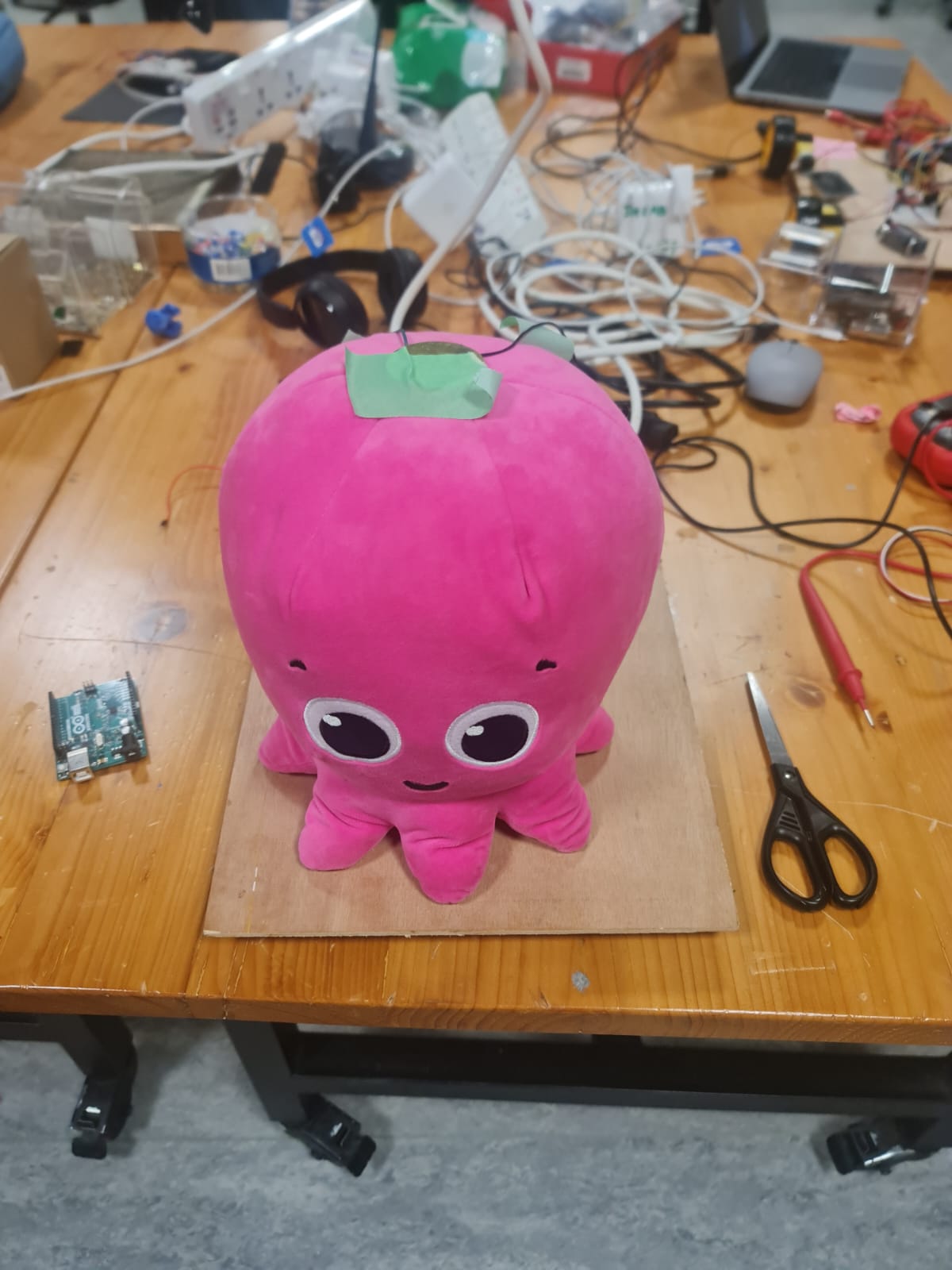
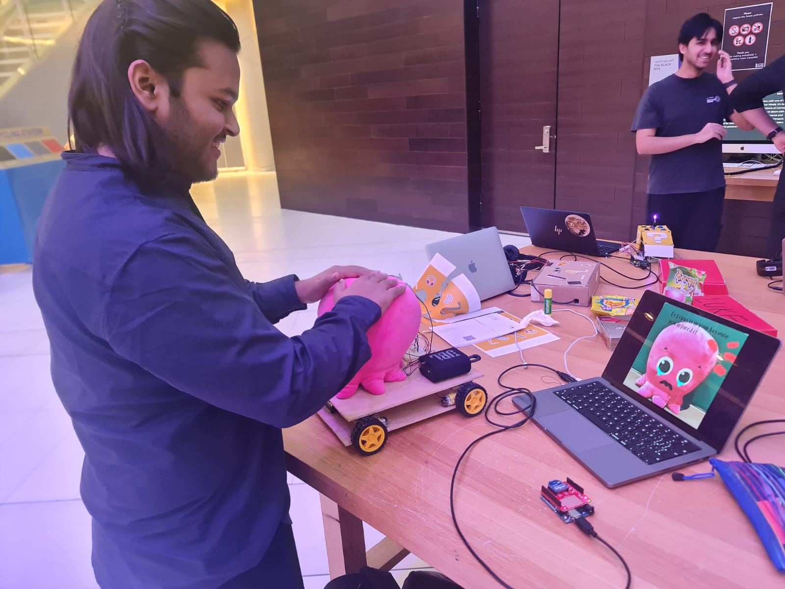
 Cover Photo
I also had an Instruction sheet for the IM Showcase in addition to the onscreen instructions on p5. This was because I observed that very few people would actually read the instructions in the beginning. A good way to make them read was to make them tangible by putting them on a piece of paper which somehow enhanced their ‘influence’ . Here is an image of the Instruction Sheet :
 Instruction text
  Key Bind visuals
Here’s a Demonstration video from the IM Showcase:
Inspiration
This started off as a joke. Literally . My friends and I had won a plushy at a game store in Dubai and we joked about how it would be so cool if I could make it move and give character to it. It sounded like a crazy and cute idea. So, I said – why not? I wanted to make something ambitious for my final project that would move wirelessly. I had initially considered a giant plushy of a Pokemon character- JigglyPuff – but realized that it was too big and I would need something smaller. So, I changed my concept to using an Octopus plushy and decided to give character and emotions to it .
I had borrowed and tried and tested lots of different sensors and modules from the IM Lab before deciding what to do and which ones to use.

19 BOOKINGS !! However, these gave me a very good idea of the resources available and how I could use them.
Most of the sensors were unreliable on a moving object and so I just used two types of sensors. Experimenting with the modules gave me an idea of how to set up wireless communication.
Concept and Interaction Design
The project consists of two main interfaces :
The Mr Octopus Robot is capable of moving forward, left, right and backward. It houses the main Octopus plushy and the movement system (using motors). A Piezosensor on top of its head is capable of detecting touch and classifies the types of touch as – (1)no touch , (2) light pat , (3) hit/pinch/ squeeze . A Photosensor senses the lighting conditions and classifies them into (1) low light(dark) , (2) medium(normal) light , (3) bright light . The emotional state of the robot is decided based on a combination of inputs from these two sensors. Since each sensor has 3 inputs each , the Octopus has a total of 9 unique emotional states.
The Project also has a p5 interface that allows the user to control the Mr Octopus Robot . The user can also play audio through the p5 interface depending upon the environment that the robot is in . The p5 interface receives the emotional state from the robot and displays a sketch/plays audio accordingly.
The bidirectional communication between the p5 interface and the Octopus Robot is enabled by 2 Arduinos and 2 XBee modules. The overall project is a unique, and fun to interact with robot that simulates emotions- making it an exciting project for anyone interested in robots that have emotions or are interactive.
Implementation
Hardware
Construction
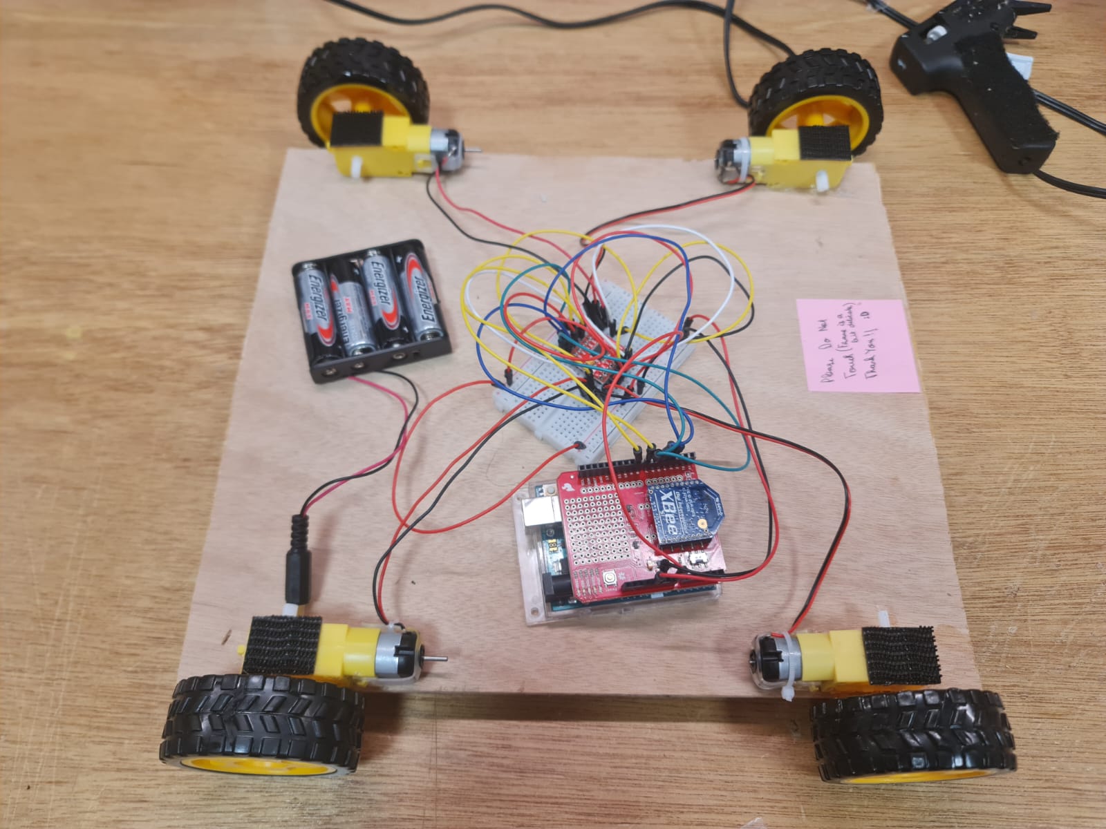
I wanted to build my robot by using 2 layers of wood. The bottom layer of wood has the Arduino for the robot , the motors , power supply and a breadboard with the motor drivers.
The top layer of wood has an Octopus plushy , Piezosensor , Photosensor, A Bluetooth speaker and a breadboard . The breadboard is connected to the main Arduino Uno through jumper wires that pass through holes drilled into the top layer.
The whole structure- that is the two layers are held together by means of velcro and folded cardboard on top of the motors .
I used the method of testing each small part of the project separately and perfecting it before integrating everything together
Below, I have given details of the steps involved in construction of the robot :
Choosing Chassis material
I used thin plywood that I was able to get from the scene shop. I drew an outline of my Octopus plushy on the plywood to get a sense of scale and left extra space for breadboard and any additional components that I would need to add in the future , then I cut two rectangles of equal size using a handsaw (Each one would form a layer of the Chassis). The scale of the framework was much bigger than the usual size of a remote-controlled robot because I needed space for the Octopus plushy on top.
Making the Lower level
I unit-tested the motors first . Since I needed four wheels, I connected two motors in parallel to each side of the motor driver. Then I wrote test code for movement, and taped the motors temporarily on their correct places to see if they work properly.
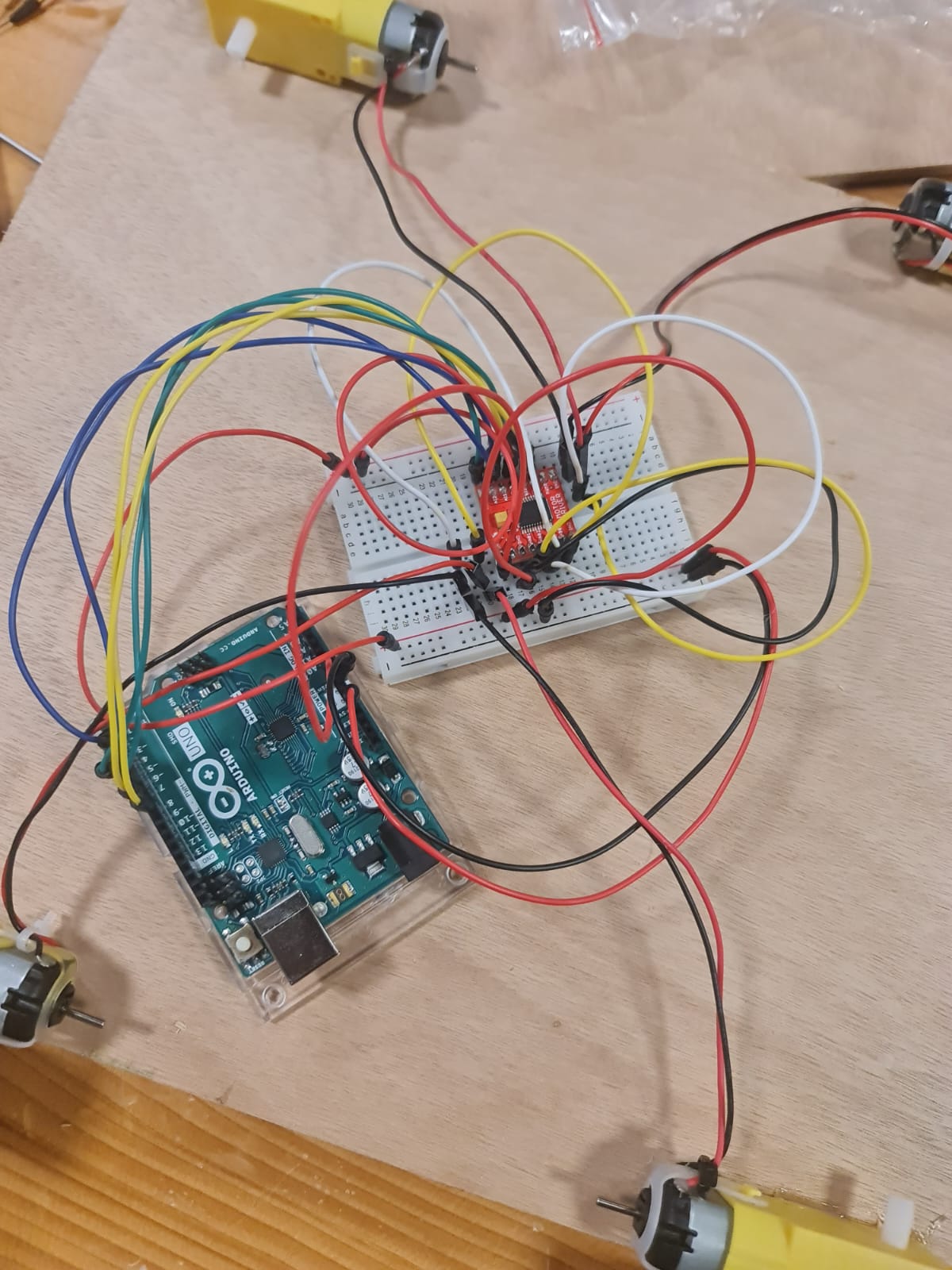 Connections
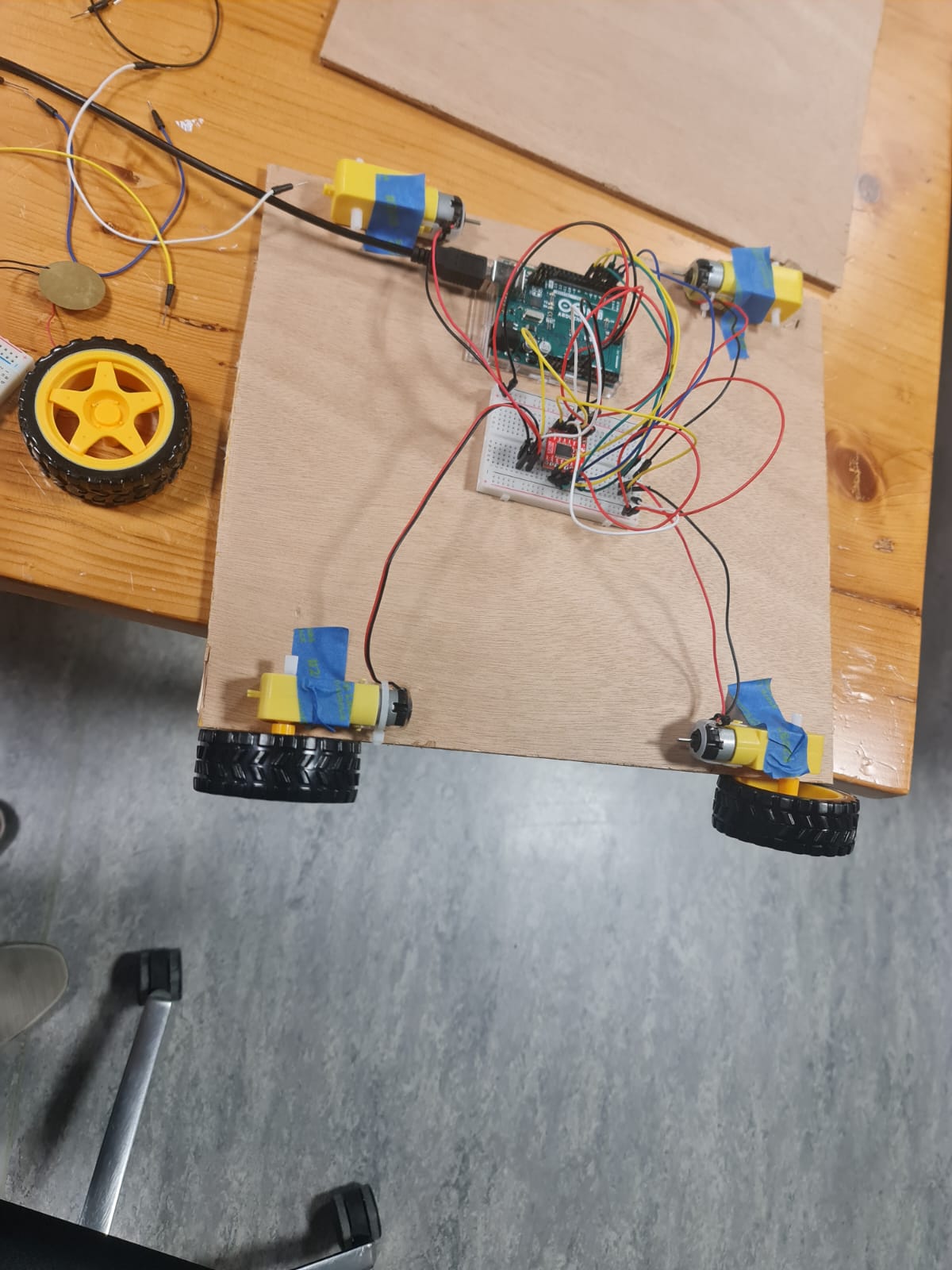 Taped Motors
Testing the movement
Once everything worked, I glued the motors to the lower level using glue gun. However, after sometime I noticed that the glue gun didn’t work well in some areas of the wood and the motors would easily come out. So, I used super glue to stick two of my 4 motors on the lower level.
Making The Upper Level.
The upper level would just contain the plushy and a breadboard for the photosensor and piezosensor connections (the photosensor would have to be at the top to detect light).
Since the Arduino Uno was on the lower level, I would need some way of connecting wires on upper level with the lower level. I measured the diameter of the jumper wires and drilled 6 holes into the upper layer above the place where the Arduino was on the lower level to allow the wires to pass through. The diameter of the holes was just smaller than the jumper wires so that the ends could be held in their place . Thus, The wires didn’t pass but just the metal ends passed through.
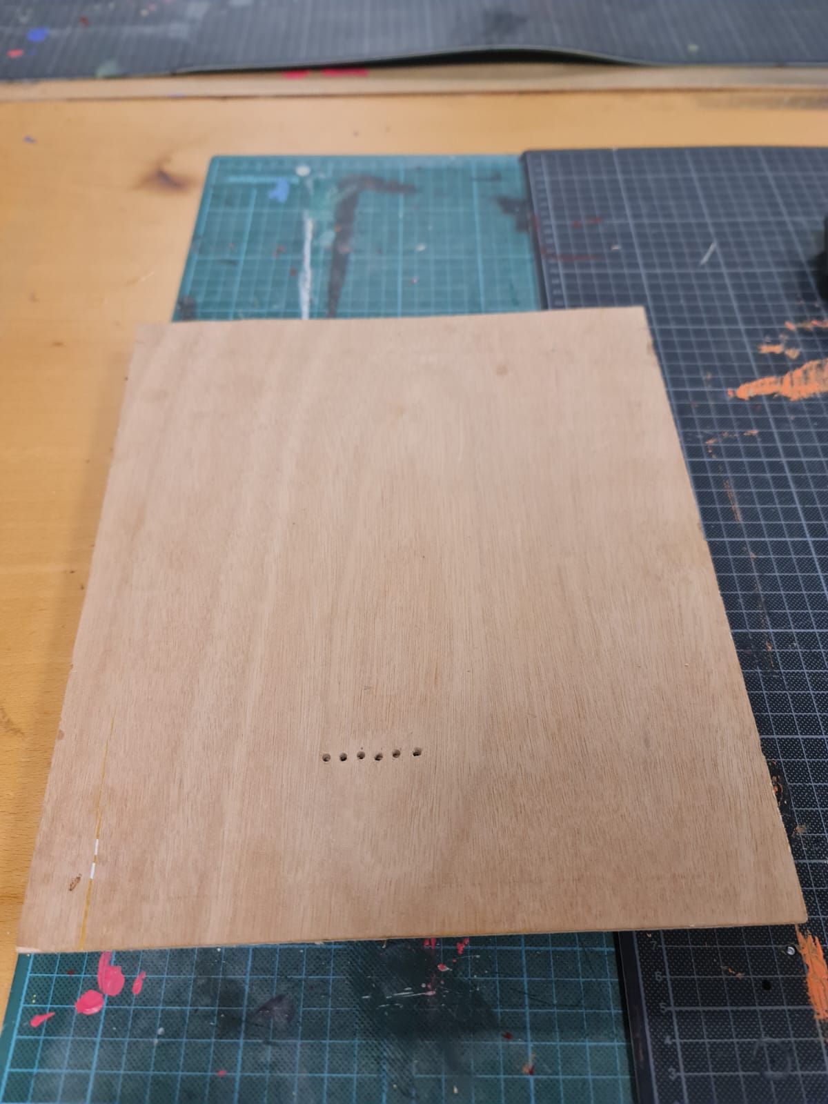 Holes for the wires
 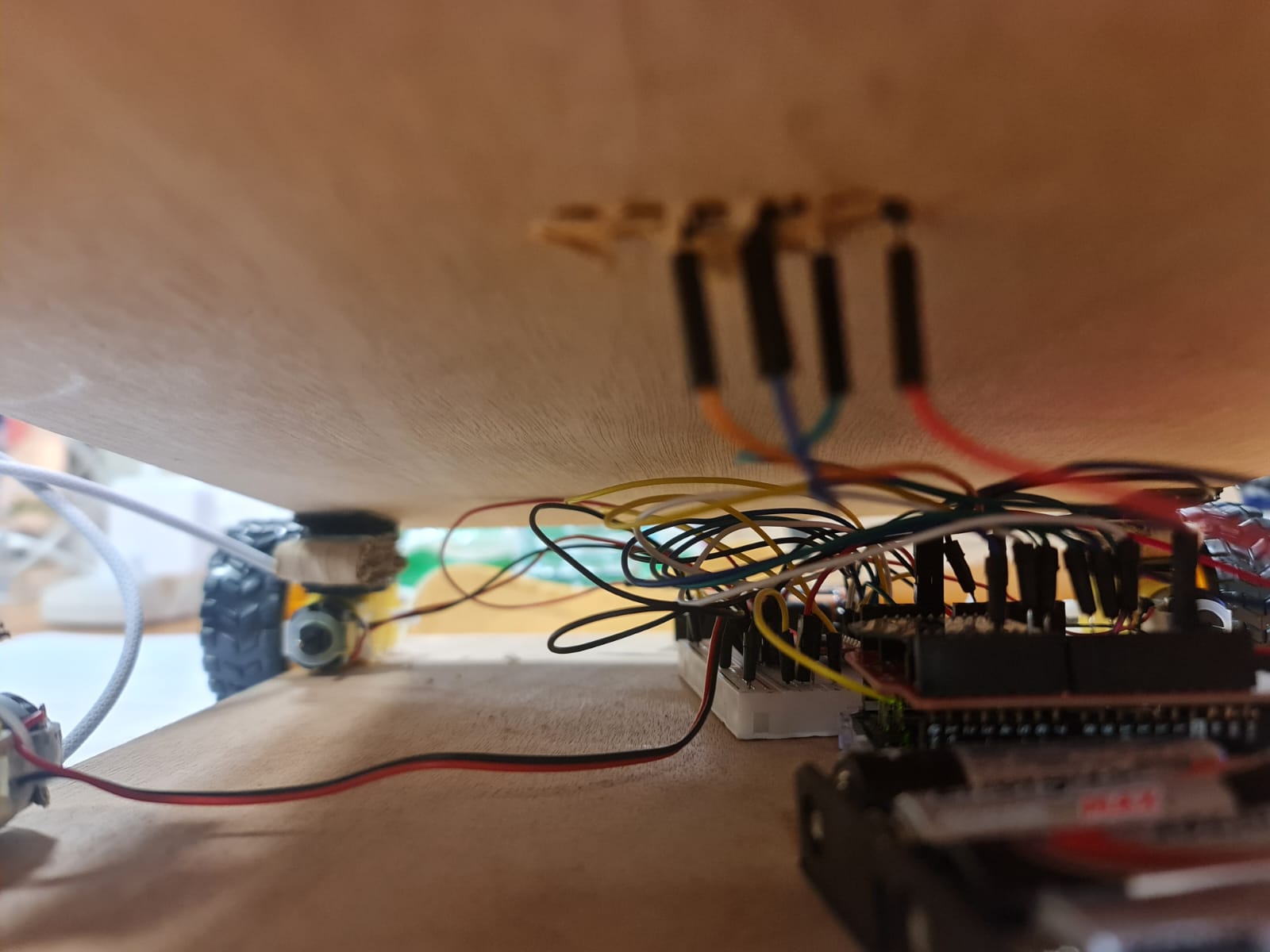 Demonstration of how wires from lower layer were eventually connected
There was another issue. The Arduino that I used in the lower layer would be taller than usual because I would have to use an XBee shield for wireless communication. There would also have to be enough space between the two layers to allow the wires to connect. This meant that I could not just stick the top layer on top of the motors directly , rather I needed some sort of padding in between to increase the height between the tp and the bottom layers.
For this purpose, I cut strips of cardboard, folded them , stuck each fold with glue gun to use as padding. One end of the cardboard padding would be attached to the motor via velcro and the other end would be attached to the top layer via velcro. Below is an image showing this: 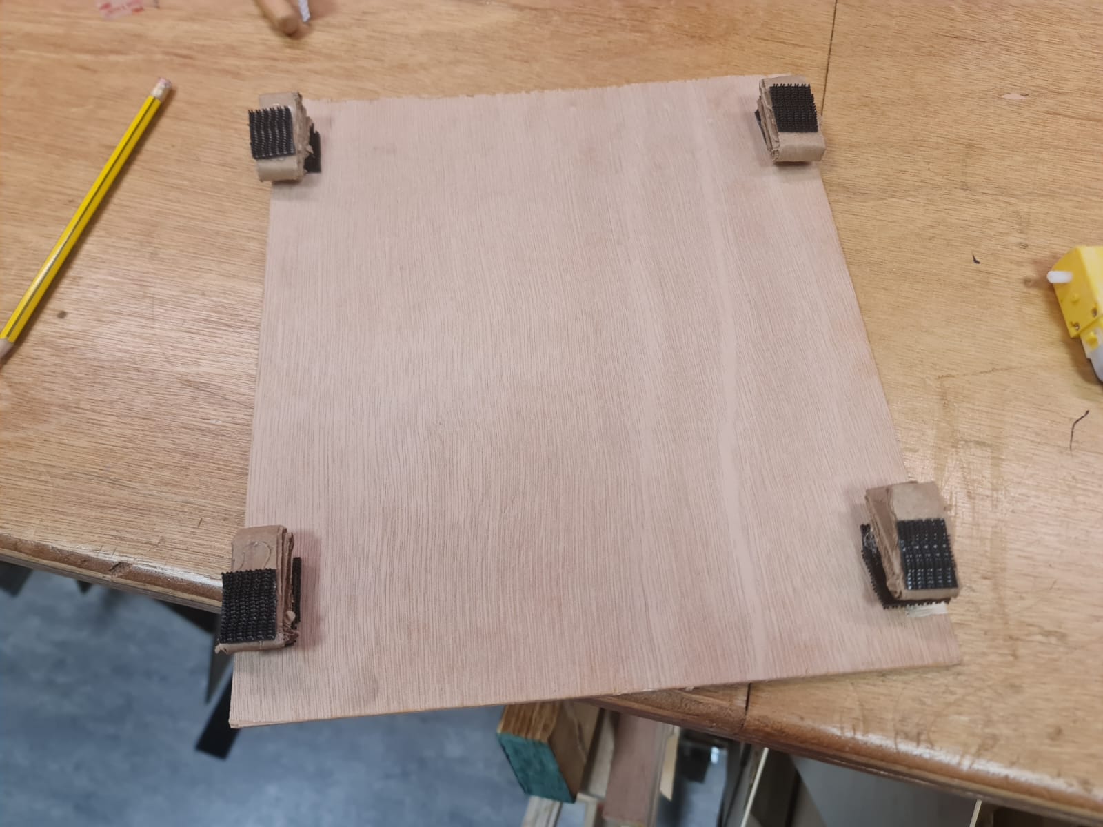 Velcro on top layer
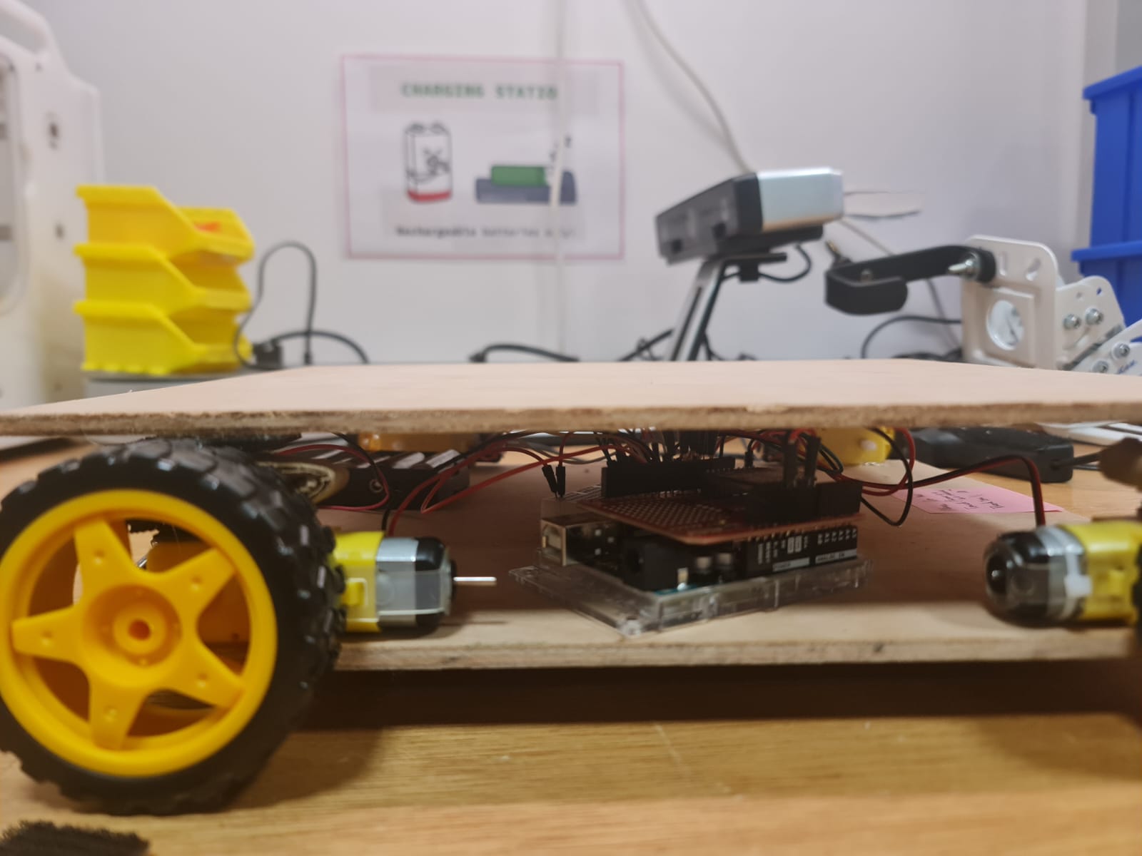 How the layers are joined and the amount of spacing between them
The use of velcro was vital as this allowed me to take the top layer off whenever I wanted.
Testing Sensors
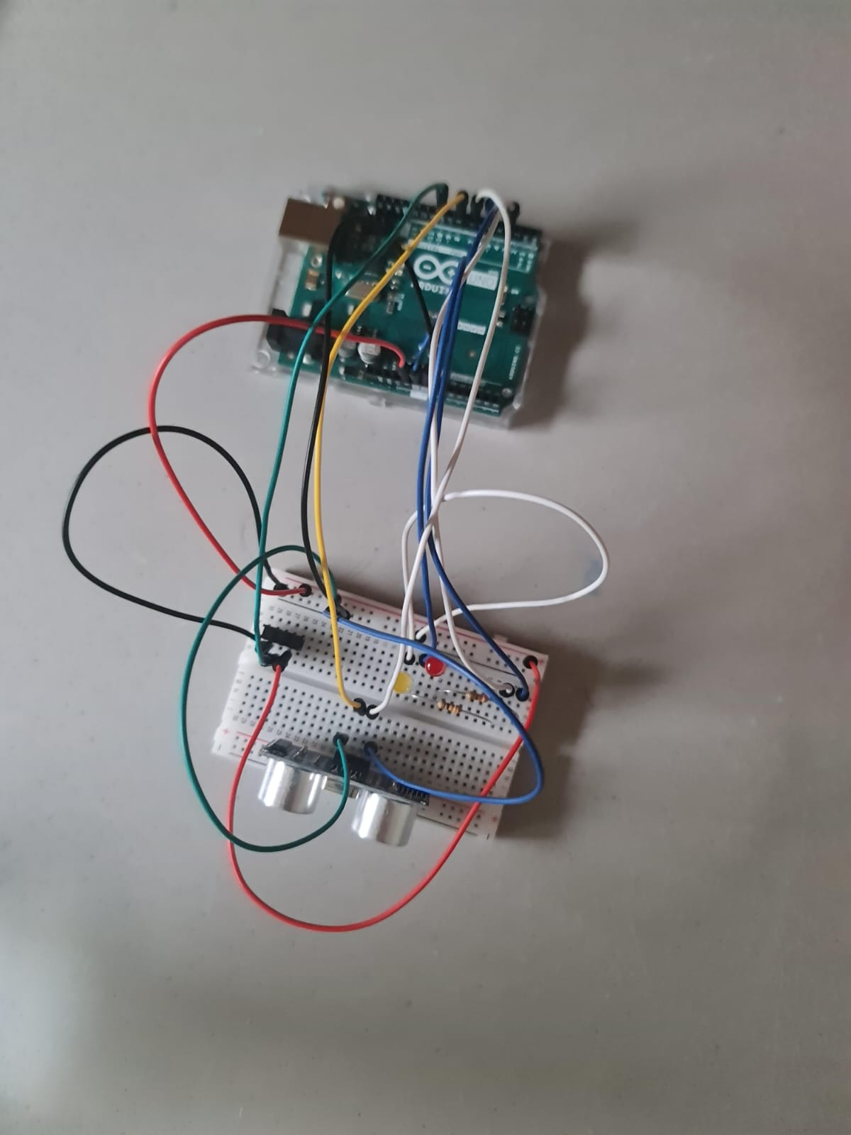
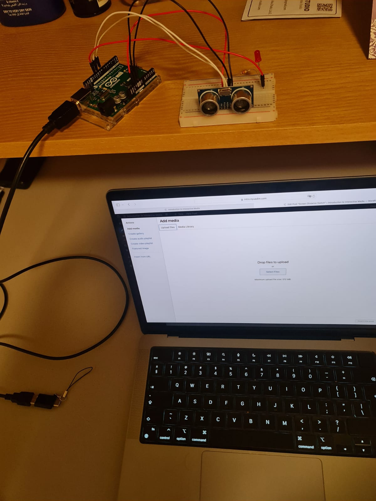
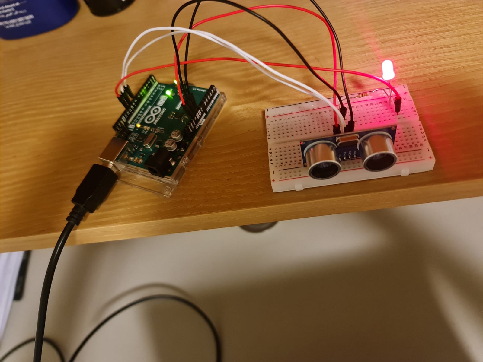
Once the motors were working , it was now time to test the sensors . For this, I used a separate breadboard and Arduino and wrote some test code to test some values and print them out on the Serial monitor to check whether the sensors were working correctly and test their range as well as the circuit connections.
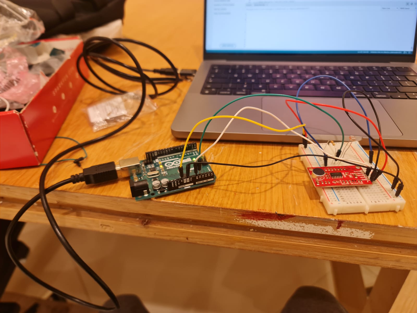 Testing sensors separately
The above image is of me testing a sound sensor and a photosensor. Although I spent a lot of time in testing and figuring out how to use the sound sensor, I decided not to include it in my final project as it was very unreliable and picked up small vibrations as sound too.
Eventually, I decided to use a piezosensor for sensing pressure on the plushy and referred to this circuit diagram – 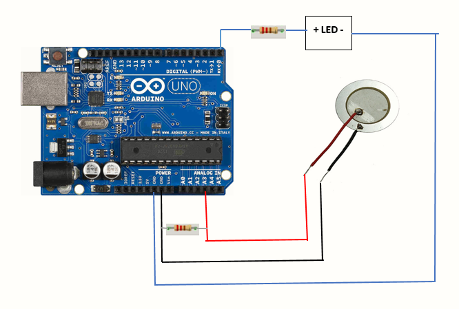 Piezosensor Circuit Diagram
Here, they recommended a 1 MegaOhm resistor but for my case , I found out that 330 Ohm resistor worked well and gave good decently spaced out values . I had some confusion while referring to the above diagram so I made the connection of the piezosensor as a classic voltage divider circuit that we studied in class. I made test code to log the values of the sensor to see how sensitive it was and what values it gave when pressed with various degrees of force.
NOTE: (For anyone trying to do this in the future), the hardest part of using the piezosensor(surprisingly) was soldering metal on the outer ring. (Please try to find an already soldered sensor) . What happens is that you have to wait for the whole sensor to get hot enough to melt the solder and this takes a very long time. I successfully soldered one sensor but then the solder came out after some time. Then, I tried with another one and the sensor broke when I applied excessive force. Eventually , everything worked fine with the third one and I was able to use that in my final project.
Integrating Power
Since I had everything on the robot running wirelessly, I needed to integrate power . Initially I had just supplied 6V to the Arduino on the robot thinking that it would be enough to power both the Arduino as well as the motors. However, it turned out that 6V was not enough to run the whole thing. So, I used a separate 6V power supply for the motors by powering the Vm pin of the motor driver with it . Even then the motors were not running at full speed. I checked the documentation for the motors and was surprised to learn that EACH MOTOR required power of 4.5 Volts to run properly which made the total power requirement 18 Volts to run the entire system properly.
 Motors that came with the kit
However, I was supplying only 6 Volts which is a third of what is required. Despite this, At maximum speed, the motors would work and the whole robot would move at a decent pace . Also, since I did not want the robot to go too fast, this was fine as long as I ensured that the batteries were replaced frequently.
Each 6V supply consisted of 4 AA batteries connected in series. The Arduino was powered through the jack. One thing I noticed was that the motors consumed a lot of power and I had to replace the batteries for the motors quite frequently. I realized that if the batteries drained even a little bit, the Voltage they would supply would go below 5 Volts and would not be enough to run the motor properly. I had tried replacing 6V supply with a 9V battery but after consulting with Professor Shiloh , I realized that the internal resistance of a single 9V battery meant that it supplied LESS current than 4 AA batteries connected in series. So, I stuck with the 6V power supply.
 Figuring out power
I arranged the cells in a battery connector from consumables .
Putting everything together (Final Integration)
This step involved sticking everything to the wooden frame at the appropriate place. For the lower level, I kept the breadboard in the center, The Arduino close to one of the edges (so that I could access its port and change code when I wanted) , and the power supply close to the Arduino (so that I could easily plug and unplug it) . For the upper layer, I arranged the plushy to the front of the board , and kept the wireless speaker and breadboard at the back. For sticking the breadboards, I just peeled the sticker at the back . The upper layer was easily joined using the velcro with cardboard padding described earlier.
I placed the plushy on top , soldered some wires and put the piezosensor on top of it .The wires are held in place by tape.
 Initial placement
 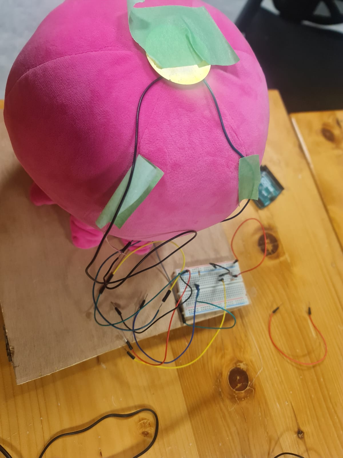 Placement of piezo sensor and photosensor
 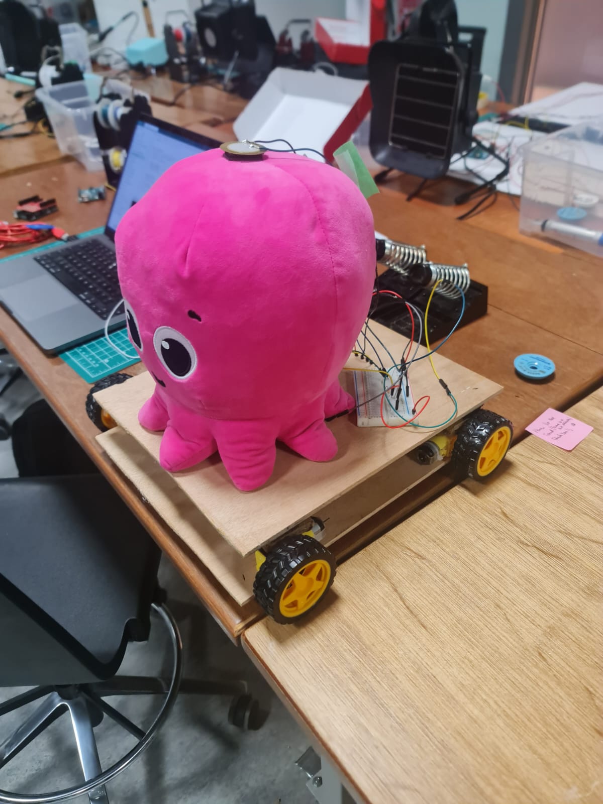 Final placement on top layer
Wireless Communication
I am using an XBee module for wireless communication. An XBee module uses radio communication . The special thing about these modules is that once configured, they can send and receive data AT THE SAME TIME. The AT THE SAME TIME part is very important as a standard radio module like NRF24L01 is not capable of this. In such modules, you will have to write code to have it receive and send data at different times. However, XBees save us from this hassle. Here is the link to the wireless kit by sparkfun – https://www.sparkfun.com/products/15936 (All components of this kit are available in the IM Lab booking system as of May 2024). The Board along with the shield looks like this : 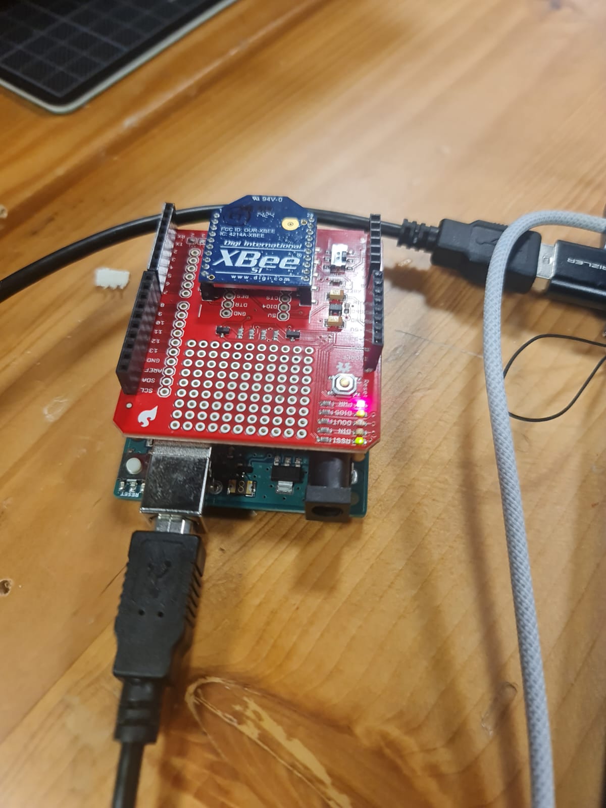 Arduino Board with XBee Shield and XBee Transmitter
I had an Arduino connected to my laptop with an XBee module – say XBee1 mounted on top with an Xbee Shield. I had another arduino on the main robot with another XBee module – say XBee2 mounted on top with another Xbee Shield.
I downloaded XCTU on my PC and configured each XBee according to the instructions in the Sparkfun tutorial using the below table as reference : This configuration is important to have everything running
What this does is it basically allows the two XBees to communicate with one another via radio communication.
My communication network then is as follows:
p5 <-> Arduino for communication <-> XBee1 <-> XBee2 <->Arduino on Robot
The communication is bidirectional at every step. It is a 5 step bidirectional communication.
XBee1 takes information from Arduino_for_communication and forwards it to XBee2. At the same time , it listens for data from XBee2.
Similarly, XBee2 takes information from Arduino_main_robot and forwards it to XBee1. At the same time , it listens for data from XBee1.
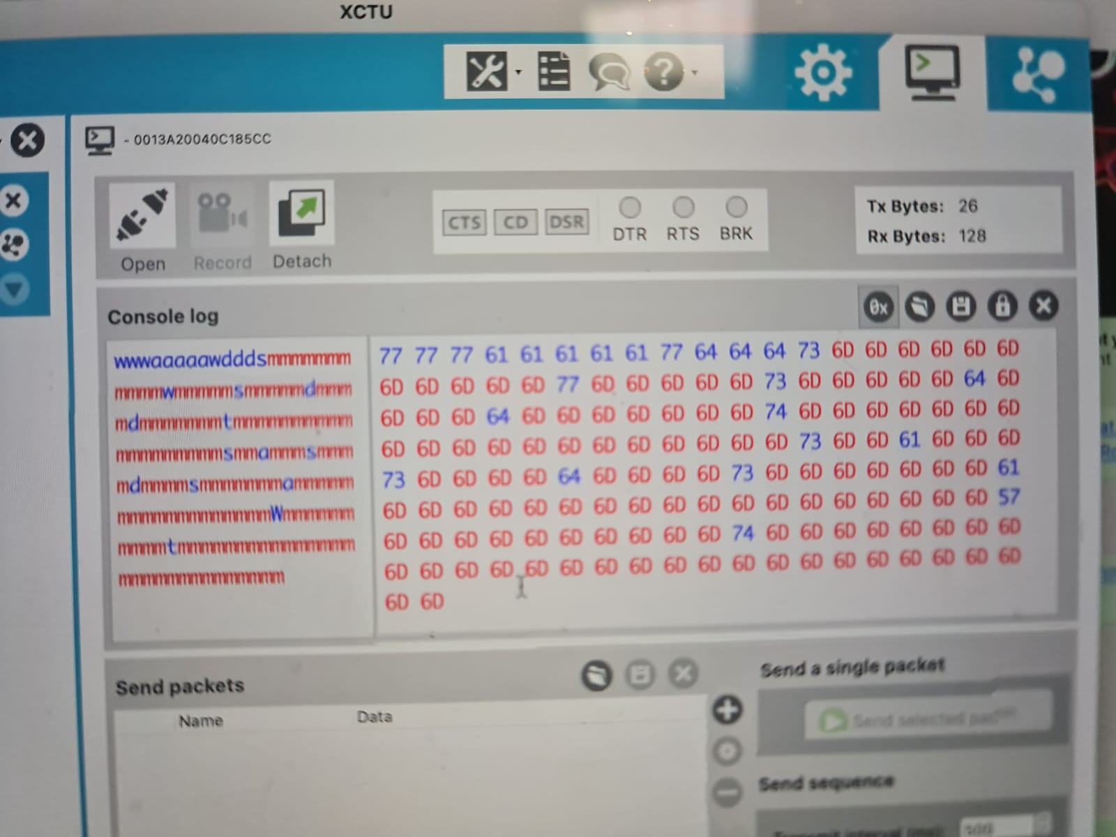
I included the <SoftwareSerial.h> library for interfacing with the XBee’s . Initially I had tested their communication and configuration and tried sending messages through XCTU which worked quite well. XCTU provided me a way to debug by seeing what messages were sent and received by the XBee.
Software
Github Link – Github_ Mr Octopus
The software consists of the p5 sketch , and two sketches for each of the arduinos . The arduino connected to the computer is called Arduino_for_comms and the one on the main robot is called Arduino_main_robot.
Arduino_for_comms reads data from p5 and forwards it to the XBee module . The XBee module on Arduino_main_robot reads this and forwards it to the arduino on the main robot. At the same time, Arduino_for_comms reads the data from XBee module and forwards it to the p5 sketch.
Arduino_main_robot reads data from the XBee module and carries out movement action according to it. At the same time, it also send data to the XBee module which forwards it to Arduino_for_comms.
One key thing to note is that Arduino to p5 communication and Arduino to Sensor communication relies on Integers , However XBee to XBee communication relies on characters. I thus needed an effective way to switch between these two data types. Neglecting this initially caused a lot of complications that are lengthy to be explained here and took a lot of time to debug but it all boils down to using the right data type.
Software side for Arduino
As mentioned, there were two Arduinos and thus two Arduino codes. The link to both of the .ino files is here :
(1) Arduino_for_comms
Link to Code- Arduino_for_comms.ino
Summary of the Code:
Listens for data from p5 sketch and sends any data it hears to the XBee module – which then forwards it to the Xbee on Arduino_main_robot . At the same time it listens to data from the Xbee module mounted on top and sends it out to the p5 sketch.
(2) Arduino_main_robot
Link to code – Arduino_Main_Robot.ino
Summary of the Code:
Listens for data from sensors – combines it to output a character and sends it to the XBee module – which then forwards it to the Xbee on Arduino_for_comms . At the same time it listens to data from the Xbee module mounted on top and moves the motors accordingly.
In addition, I had also used several Arduino sketches for unit testing motors, sensors and communication . The following is a link to these sketches :
Software Side for p5
Here is the p5 sketch:
To check and test, run it on Chrome , setup the serial , and you can change Val1 in the code to switch the sketch, press option to play introduction sound when sketch is happy and shift to play sound according to the emotional state
Description of emotional states of the robot
The p5 sketch changes according to the environment or emotional state of the robot. The robot has the following emotional states:
- Peaceful (Normal light , no touch)
- Vibing in the light (High light, no touch)
- Sadness in the dark (Low light, no touch)
- Loved normal (Normal light, Gentle touch)
- Loved Bright (Bright light, Gentle touch)
- Loved Dark (Low light, Gentle touch)
- Hurt normal (Normal light, Hit/pinch)
- Hurt dark (Low light, Hurt/pinch)
- Hurt Bright (Bright light,Hurt/pinch)
The p5 sketch changes according to the emotional states of the robot . These states are determined by the following readings from the piezo sensor and photosensor ( I tweaked them a little to adjust for light in the arts center).
For Piezosensor :
- >= 70 is counted as a hit
- >20 and <70 is counted as a pat
- <20 is counted as no touch
For Photosensor :
- >900 is counted as bright
- <900 and >550 is counted as normal light
- <550 is counted as dark .
Design elements
Visuals
I have a different image for each of the emotional states. The images are listed below :


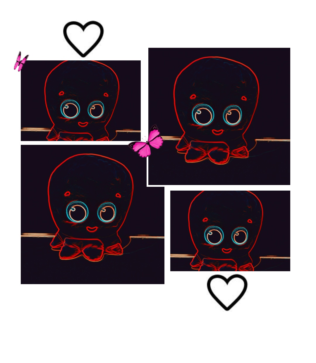


Every Visual above was generated using a mixture of snapchat filters, the LUMI app . Some features were drawn by SPen on my mobile phone. Snapchat filters were very useful for the whole visual generating process.
Audio
I used the following audio files in my project :
- Octopus Trimmed.mp3 – which is an audio that introduces the Octopus, it is a snippet of the following YouTube video : PinkFog Octopus hello
- Peace_Trimmed.mp3 – This is the peaceful sound effect that I adapted from Kung Fu Panda.
- Sad_Piano.mp3 – Sad sound sourced from Pixabay
- Loved_music.mp3 – Calm soothing sound effect from Pixabay
- Vibe_music.mp3 – Groovy sound effect from Pixabay.
The sounds are played according to the emotional state of the Octopus . The introduction sound can be played by pressing the (option) key when the octopus is in an emotional state that is NOT SAD.
Fonts
I have used the following Fonts in my project:
- ArtFully Regular.ttf
- Hartford.ttf
- NoteToSelf – Regular.ttf
- NoteWorthy Bold.ttf
- Sportfield Varsity Stacked.ttf
Summary
Here’s a summary of all assets I have used (code snippet from p5):

User Testing
The users reported that the sideways movement is a bit slow. I suspect this is due to the 6V power supplied for the motors instead of the 12V that they require (Each motor requires around 3V -> but I have supplied all 4 motors with 6 Volts) . This is fine as I do not want the robot to move too fast.
Initially I was using a click mechanism for playing sound but a user said that using the option key and the shift key would be much better so I decided to use these keys in addition to the click mechanism. This is also reflected in the Instructions sheet.
I don’t have any particular videos of User testing but I asked for advice from Lab assistants and other people working at the IM Lab. Here’s a video of a user testing movement and the introduction interaction
I realized the movement should be faster and the reason it wasn’t fast enough was because the batteries had drained and were supplying less voltage than usual so I just took the top off (which was easy since it is attached by velcro) and replaced the batteries.
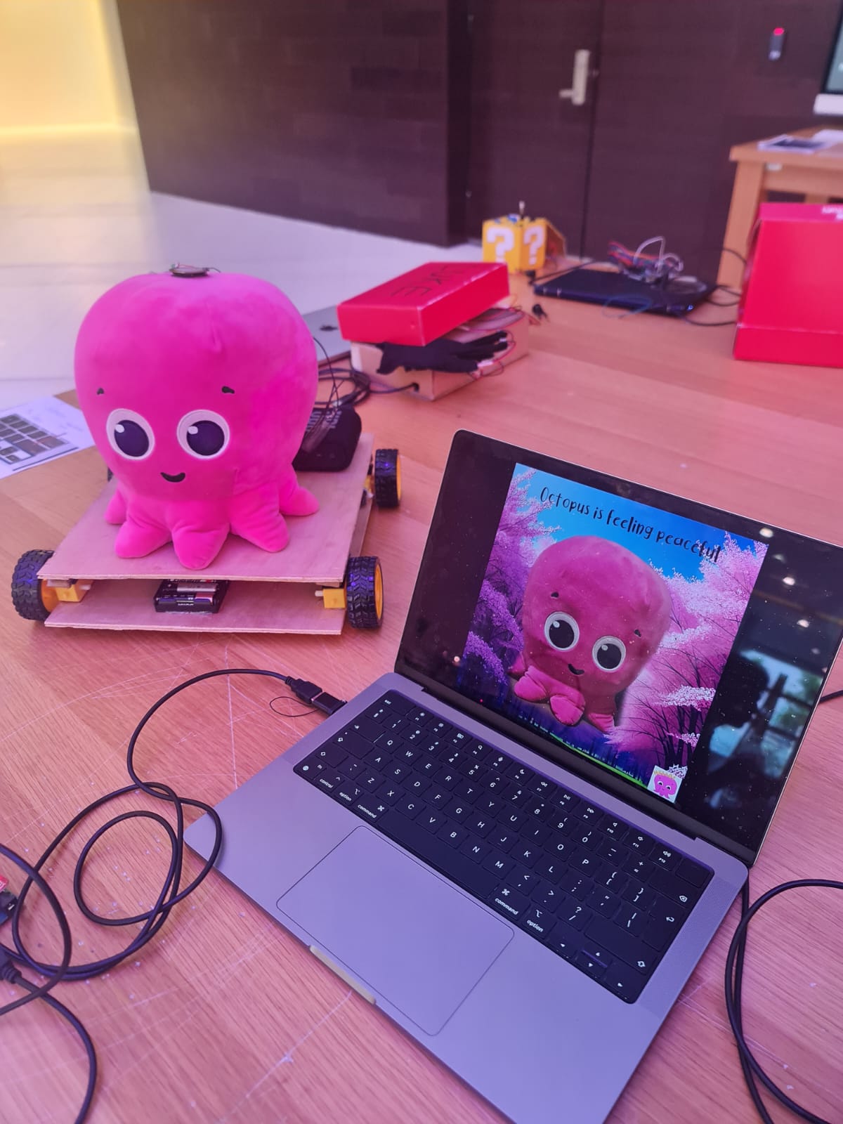
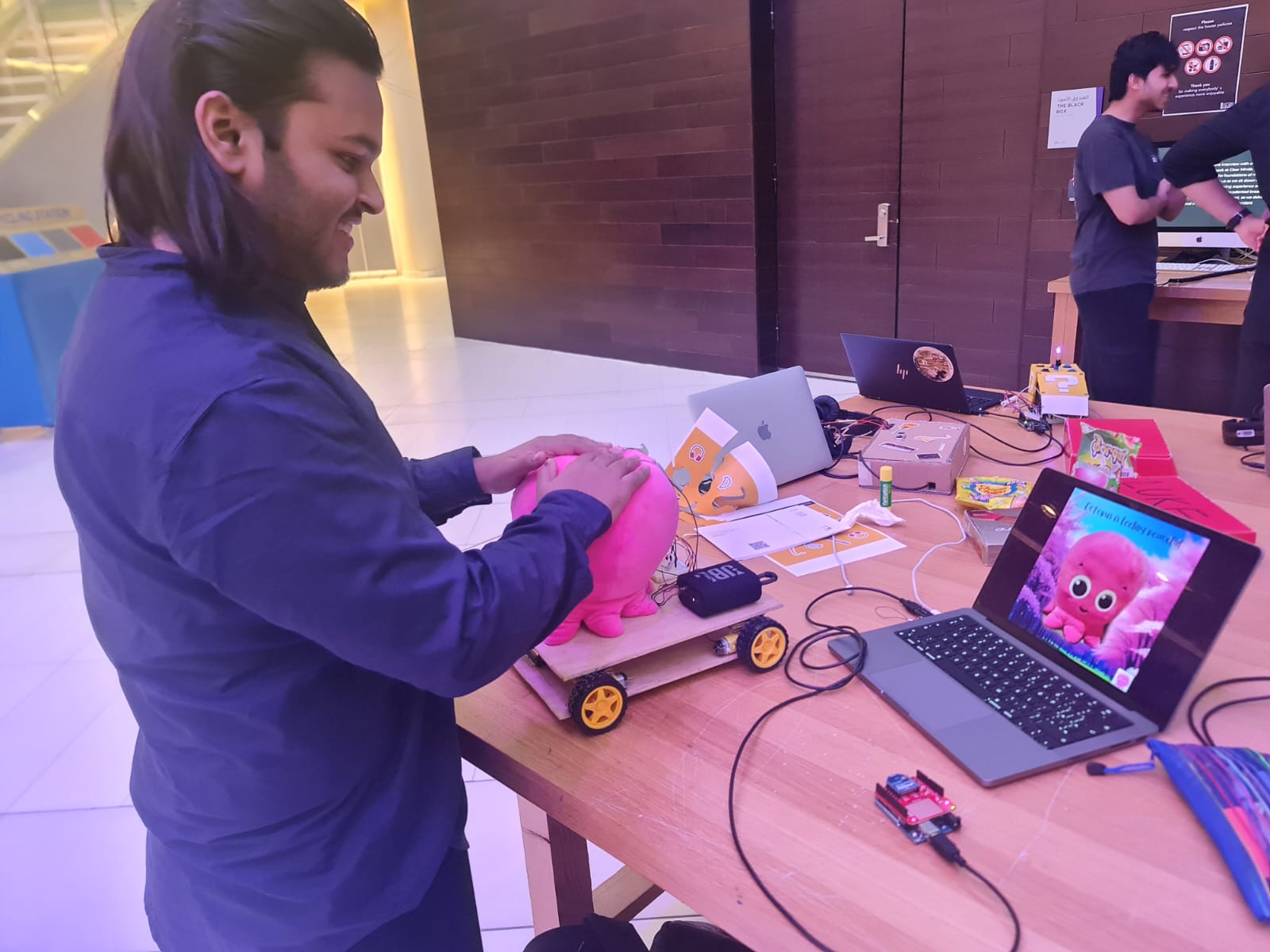
IM Showcase
The Showcase went amazing!! People gave really good reviews and a lot of people enjoyed playing with the robot and interacting with it. At times , they would drive it over to random people and say hello. Several people said that the project was technically impressive and cute.
A lot of people took photos with and of my project . There is a slight issue though – I barely took any videos 🙁 – However, I do have some recordings of people trying it out and they are attached below :
I felt very happy watching people interact with it and really enjoyed watching them get surprised when trying out different interactions such as the introduction sound and pressing with force on the piezosensor(on the top of the Octopus) that triggers hurt sound and hurt image.
Potential Future Developments
This project could be potentially improved by :
- Making a stronger frame or chassis that would enable the whole structure to move faster without risk of damage.
- Integrate more sensors such as sound sensor and human presence sensor.
- Play audio through a Music maker shield rather than using a bluetooth audio speaker.
- Easier braking system – right now , because of the way the code and character conversion works the only way to brake is to press the down key followed by either left or right arrows. With a little bit more code editing and correct power for the motors, I could fix this and change the key binding for brake to something simpler such as a spacebar.
- A system for autonomous movement
Challenges and Things learned
Heads up to anyone making something similar in the future- You have chosen an ambitious project !! The following are some challenges I faced that I can recall and how I fixed that . Hopefully, this can be of some help to you –
- Integrating power – The DAGU motors we are given in the sparkfun kit need a power of 4.5 V EACH for optimal running. This sounds like a lot and it is a lot but be mindful that anything less than this and the motors may not function properly or may turn slower than expected. This is the issue I faced when the motors were not working correctly
- Wireless Communication – Use XBees : People have used NRFL01 modules previously because they are cheaper and smaller but if XBees are available in the booking system , use them. The difference is that XBees can SEND and RECEIVE data at THE SAME TIME. Check out the sparkfun tutorial on setting them up and you should be fine . This is not possible for the NRF modules and it is a hassle to achieve wireless bidirectional communication with them (people have done it in the past , but it’s more difficult than just using XBee) . NOTE: XBee modules used pins 2 and 3 for Rf-Tf on Arduino UNO for communications so do NOT connect anything to these pins. I missed that and spent a lot of time debugging.
- Use VELCRO: Lifesaver !! I could dismantle by whole project to replace new batteries or upload code to the Arduino or rewire connections because I had connected the layers with Velcro. Velcro is super super useful .
- Soldering on a Piezosensor – Very difficult !! Try using a sensor that already has soldered wires. If not check the construction section of this documentation. I faced a lot of difficulty soldering them. Some are very sensitive and break if you apply too much pressure.
- Playing Audio in p5 – Always set play mode to ‘restart’ if you are calling play() in loop . you can use setVolume() function to adjust the audio in your sketch (you have to include a library but this is very useful) .
- Make Room for Recalibration- I ended up gluing my Arduino to a hard to reach place in the lower level . This was a serious issue as I faced difficulty trying to reprogram it . Eventually, I was able to somehow sneak the connector in. If you are using light or infrared sensors, you will HAVE TO RECALIBRATE them while setting up as the lighting during showcase is different from lighting in IM lab . Be mindful of this and make sure you can recalibrate easily.
- If using XBee, be mindful of the datatypes they can send and receive, use XCTU for debugging. I spent a lot of time debugging because I used the wrong datatype.
- Try to reuse the starter code given by professor and adapt it accordingly – it’s way easier than writing from scratch which is what I tried doing initially.
Reflections (Proud Of !!)
When I had selected this topic , I knew it was a fun challenging project to work on. Looking at past documentation, I realized that very few students had implemented bidirectional wireless communication before and this is generally difficult to implement. I spent several days trying to configure my XBees and setting the power for my project correctly. Then , I spent several hours trying to figure out how to convert between appropriate datatypes for the 5 way communication. at one point, I thought that I wouldn’t be able to complete on time .
Despite that I was able to not only set up bidirectional wireless communication, but was also able to create a great design for the p5 sketch which I am really proud of . The project at the end turned out better than my expectations and the positive reviews and appreciation from Professors and Students at the IM Showcase made me very happy !!
There were lots of things I had to learn on my own for this project – from setting up XBees, to integrating power, soldering wires the right way, testing several sensors, making a chassis, using a piezosensor- It was a great experience. At the end , I was able to deliver on the high expectations I had for myself for the final project and I am very proud of that .
Special Thanks to ……
I would like to Thank the following people . This project wouldn’t be possible without their help, support and guidance-
- Professor Aya Riad for teaching the course, following through with my project, encouraging me to make innovative projects , and helping me with ideas.
- Professor Michael Shiloh for help with debugging and testing the motors +help with soldering on the piezosensors.
- Stefania and Ume for their help with using IM equipment and support .
- All the Lab Assistants – Basil , Khadijah , Ramsha, Raya, Aadhar, Moeez, Dania, Arslan, Aya for helping and assisting me in my project as well as dealing with all of my check ins and check outs .
- Sanansh Garg for allowing me to kidnap his Octopus Plushy and for User testing.
- Swostik Pati and Sri Pranav Srivatsavai for guidance on how to set up bidirectional communication , for their amazing documentation – and for starting the joke to put a Jigglypuff on top of a car.
- Nikhil Mundra for the mini JBL Speaker that made wireless audio possible.
- All of my Classmates across all sections especially in mine.
- Everyone who came to the IM Showcase .
- Everyone else who helped me , provided support and kept company . It was a pleasure working with you all !!


 Schematic Diagram
 View on TinkerCAD
 List of Components