FINAL PROJECT – GOAL RUSH

CONCEPTS:

The game is a fast-paced, reaction-based experience inspired by the Speed Light Reaction Game, which I transformed into something I’m passionate about: football. The game requires players to quickly respond to an LED light by pressing the correct button. If they react correctly, they score a goal, but if they miss or press the wrong button, the ball hits a mannequin, simulating a failed attempt. The game incorporates visual and auditory feedback, a playlist of music inspired by FIFA, and a timer to create an engaging and immersive experience that challenges players’ speed and reaction time.

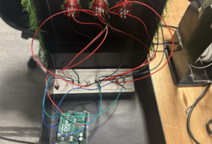
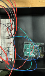
IM SHOW:

IMG_1736 2

IMG_1734 2

USER TESTING:

user_testing (1)

THE GAME:

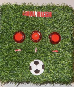
the button (the control)-

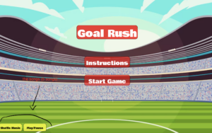
the layout

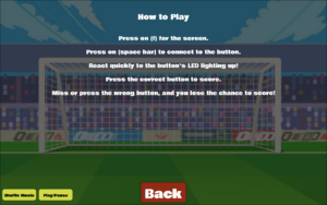
the instruction page

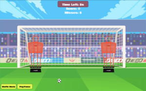
the game play page

P5 SKETCH:

SETUP:

How does the implementation work?

The game uses Arduino and p5.js software for an interactive experience.

  1. Hardware (Arduino):
    • LED button lights serve as control, which lights up signaling which button to press to score, allowing user input.
    • Serial communication sends user responses from the Arduino to P5.js.
  2. Software (p5.js):
    • Manages game visuals, including the football, goal, and mannequins.
    • Tracks scores, missed shots, and the countdown timer.
    • Plays music and sound effects to immerse players in the experience.

INTERACTION DESIGN

  • Title Screen:
    • Features:
      • Displays the game title with an bold font.
      • Includes buttons for “Start Game”, “Instructions” and “shuffle – play/pause” for music.
    • Design Choices:
      • Used bold colors and a clean layout for clarity and visual appeal.
    • Gameplay:
      • Press the matching led button that lights up to score.
      • Correct button presses make the ball move toward the goal, simulating a successful shot.
      • Incorrect or missed presses (not pressed within 1 sec) result in the ball hitting a mannequin, simulating a failed shot.
      • Additional on-screen buttons allow players to shuffle music or play/pause background tracks.
    • Feedback: The game uses visual (ball movement) and auditory (goal or miss sounds) feedback. Background music inspired by FIFA enhances the immersive experience
  • End Screen:
    • Displays the final score and missed attempts.
    • Includes buttons to restart the game or return to the main menu

DESCRIPTION OF P5.JS CODE:

The p5.js sketch manages the visuals, sounds, and game state.

  1. Key Features:
    • Dynamic Visuals: Updates scores, displays animations for goals and misses, and tracks time.
    • Audio Feedback: Plays sound effects for scoring and missing.
    • Serial Data Handling: Receives and processes data from Arduino.
  2. Code Snippets:
    • Serial Data Handling:
function readSerial(data) {
  if (data === "BUTTON:CORRECT") {
    score++;
    // Animate football to the goal
  } else if (data === "BUTTON:WRONG") {
    missedShots++;
    // Animate football to the mannequin
  }
}
  • Music Control:
function toggleMusic() {
  if (isMusicPlaying) {
    backgroundSounds[currentTrackIndex].pause();
    isMusicPlaying = false;
  } else {
    backgroundSounds[currentTrackIndex].play();
    isMusicPlaying = true;
  }
}

DESCRIPTION OF ARDUINO CODE:

The Arduino code handles LED prompts, button detection, and serial communication with p5.js.

Key Components:

  1. LED Control:
    • LEDs light up randomly, prompting user action:
void lightUpLED(int index) {
  for (int i = 0; i < 3; i++) {
    digitalWrite(ledPins[i], (i == index) ? HIGH : LOW);
  }
}
  • LEDs turn off after a button is pressed or the timeout ends:
void turnOffLEDs() {
  for (int i = 0; i < 3; i++) {
    digitalWrite(ledPins[i], LOW);
  }
}

Button Detection:

  • Checks if the correct button is pressed:
void checkButtonPress() {
  if (targetLED != -1 && digitalRead(buttonPins[targetLED]) == LOW) {
    Serial.println("BUTTON:CORRECT");
    targetLED = -1; 
    turnOffLEDs();
  } else {
    for (int i = 0; i < 3; i++) {
      if (i != targetLED && digitalRead(buttonPins[i]) == LOW) {
        Serial.println("BUTTON:WRONG");
        targetLED = -1; 
        turnOffLEDs();
        break;
      }
    }
  }
}

Serial Communication:

  • Sends formatted data to p5.js:
void sendLEDSignal(int ledIndex) {
  Serial.print("LED:");
  Serial.println(ledIndex);
}

Listens for responses from p5.js:

if (Serial.available()) {
  String command = Serial.readStringUntil('\n');
  if (command.startsWith("LED:")) {
    targetLED = command.substring(4).toInt();
    lightUpLED(targetLED);
  }
}

COMMUNICATION BETWEEN P5 AND ARDUINO:

How It Works:

  • Arduino sends data about user responses (correct or wrong button presses) to p5.js.
  • p5.js uses this data to update the game state:
    • Correct responses move the football to the goal and increase the score.
    • Incorrect responses move the football to a mannequin and increase missed attempts.
  • p5.js also sends signals back to Arduino to light up LEDs.

Challenges Overcome:

  • Initial miscommunication due to overlapping signals was resolved by implementing a debounce delay in Arduino and validation logic in p5.js.

CHALLENGES FACED:

One major challenge was managing communication between Arduino and p5.js. Initially, multiple data packets were sent for a single button press, causing disruptions in the game. To fix this, I added a debounce delay in the Arduino code:

if (magnitudeG > impactThreshold) {
  Serial.print("BUTTON:CORRECT");
  delay(200); // Debounce to avoid multiple signals
}

This ensured only one signal was sent per button press. I also validated inputs in p5.js by processing only expected packets like "BUTTON:CORRECT", which resolved signal misinterpretations.

Another challenge was ensuring strong soldering connections for the buttons and LEDs. My first attempts were unreliable, but then I secured the connections, improving hardware stability.

WHAT IM PROUD OF:

I’m proud of successfully integrating Arduino and p5.js to create a smooth and responsive game. Features like the animated football, scoring system, and FIFA-inspired music enhanced the user experience. Solving technical issues, such as serial communication and soldering, was rewarding, as they significantly improved the gameplay experience.

FUTURE IMPROVEMENTS:

One improvement would be adding a game mode where pressing the correct button contributes to building a beat or rhythm for a song. Each correct button press would play a specific musical note or drum beat, gradually creating a complete soundtrack as the player progresses. This mode would combine the fast-paced reaction element with creativity, making the game more dynamic and engaging. By turning gameplay into a musical experience, it would appeal to a broader audience and add a unique layer of interactivity. This feature could also include different difficulty levels, where faster reactions create more complex beats, challenging players’ skills and rhythm simultaneously.

RESOURCES USED:

https://www.instructables.com/Plug-and-Play-Arcade-Buttons/

https://editor.p5js.org/jps723/sketches/Byvw1lu6Z


FINAL PROJECT – USER TESTING

USER TESTING:

user_testing

FEED BACK:

At first, creating the game was challenging because I struggled to get the buttons to function the way I wanted them to. Mapping the LED buttons to the gameplay and ensuring they triggered the correct actions was particularly difficult. However, I overcame this by refining the logic for button inputs and testing repeatedly to ensure everything worked as intended. This process required a lot of trial and error, and it was hard to troubleshoot the interactions between the controls and the game logic. Despite the difficulties, resolving these issues was rewarding and helped me improve my understanding of how to create interactions in the game.

During user testing, most users were able to figure out the game easily as the instructions were clear; however, I had to explain to some users that this is a reaction-based game where they need to react to the LED button that lights up and not to focus on the defenders on the screen. While the instructions were effective, a few players needed additional clarification about the LED mapping and corresponding button. Once users understood the concept of reacting to the LED, the gameplay became much smoother. Also, I need to fix a minor issue where when the users press start, the positions of the manequins wouldn’t be where they were supposed to be until a few seconds later, it gets fixed. However, the experience worked well overall, with the audio feedback for scoring and missing enhancing the immersion. The visual design also made the game enjoyable, and the fast-paced gameplay kept users engaged. To improve the experience, I plan to add a more detailed instruction page to eliminate the need for further explanation and slightly increase the reaction time to make the game more accessible for new players. Additionally, I was inspired by the FIFA game and would like to incorporate a shuffled playlist for background music to elevate the experience further and create a more engaging atmosphere.

FINAL PROGRESS – GOAL RUSH

Finalized Concept for the Project

For my final project, I will create Goal Rush, which is a football reaction game where the player acts as a goalkeeper in a penalty shootout. The goal is to save as many penalty shots as possible by reacting to random signals. The project uses a physical setup with three buttons and corresponding LEDs to simulate the direction of the ball (left, center, or right). Each button press simulates the goalkeeper’s dive to save the ball.

The buttons, LEDs, and game logic are connected to and managed by an Arduino. The Arduino communicates with a p5.js program, which mirrors the physical gameplay with a digital goalpost, goalkeeper, and ball animations. The LEDs light up to signal where the ball is “shot,” and the player must press the corresponding button to save the goal. The correct press sends a signal to p5.js, making the goalkeeper dive in the corresponding direction. If the player reacts too late or presses the wrong button, the ball goes into the net, and a missed goal is recorded.

Arduino Program Design

  1. Buttons:
    • Button 1 (Left):
      • Connected to digital pin 2.
      • Represents the goalkeeper diving to the left.
    • Button 2 (Center):
      • Connected to digital pin 3.
      • Represents the goalkeeper staying in the center.
    • Button 3 (Right):
      • Connected to digital pin 4.
      • Represents the goalkeeper diving to the right.

What It Does:
Each button, when pressed, sends a signal to the Arduino. The program identifies which button was pressed and determines if it corresponds to the lit LED.

  1. LEDs:
    • LED 1 (Left):
      • Connected to digital pin 5.
      • Lights up to indicate the ball is being “shot” to the left.
    • LED 2 (Center):
      • Connected to digital pin 6.
      • Lights up to indicate the ball is being “shot” to the center.
    • LED 3 (Right):
      • Connected to digital pin 7.
      • Lights up to indicate the ball is being “shot” to the right.

What It Does:
The LEDs are controlled by the Arduino to light up randomly, signaling where the ball is heading. This gives the player a cue for which button to press.

  1. Wires:
    • Signal Wires: Connect each button and LED to their respective digital pins on the Arduino to transmit input and output signals.
    • Power Wires: Connect all components to the Arduino’s 5V and GND pins to ensure proper power supply.

Arduino Program Workflow:

  1. Random LED activation:
    • The Arduino randomly selects one of the LEDs (left, center, or right) to light up, signaling the ball’s direction.
    • A small delay allows the player time to react.
  2. Button Monitoring:
    • The Arduino continuously checks the state of the buttons using digitalRead.
    • If a button is pressed, the Arduino determines whether it matches the lit LED:
      • Match: Sends a success signal (-1, 0, 1 based on the button pressed) to p5.js.
      • Mismatch or No Press: Sends a failure signal to p5.js.
  3. Serial Communication:
    • Sends the button state (-1, 0, or 1) and save/miss result to p5.js, where the digital game is updated accordingly.

p5.js Program Design

  1. Digital Goalpost:
    • Displays three zones (left, center, right) where the ball can be shot.
  2. Digital Goalkeeper:
    • Moves left, center, or right based on data received from Arduino (-1 for left, 0 for center, 1 for right).
  3. Ball Animation:
    • A ball is animated to travel toward one of the three zones, matching the lit LED in the physical setup.
  4. Scoreboard:
    • Tracks successful saves and missed goals.
  5. Game Timer:
    • Limits the game duration and increases difficulty by speeding up the ball animations over time.

p5.js Program Workflow:

  1. Input from Arduino:
    • Receives data from Arduino indicating which button was pressed and whether it was correct.
    • Updates the goalkeeper’s position (left, center, or right) based on the button data.
  2. Random Shot Generation:
    • Randomly determines the ball’s trajectory (left, center, or right), mirroring the Arduino’s LED activation.
  3. Collision Detection:
    • Checks whether the goalkeeper’s position matches the ball’s trajectory when the ball reaches the goal:
      • Match: Displays a save animation and increases the score.
      • Mismatch: Displays a missed goal animation.
  4. Visual Outputs:
    • Updates the digital display to show the ball’s movement, the goalkeeper’s dives, and the game’s score and timer.

WEEK 11 – EXCERSISE

EXCERCISE 1: ARDUINO TO P5.JS COMMUNICATION

RESULT:

IMG_1537

P5.JS:

CODE (P5.JS):

let sensorValue = 0; // Variable to store sensor data

function setup() {
  createCanvas(640, 480);
  textSize(18);
  if (!serialActive) {
    setUpSerial(); // Start serial communication with Arduino
  }
}

function draw() {
  // Set the background to dark blue and purple hues based on the sensor value
  background(map(sensorValue, 0, 1023, 50, 75), 0, map(sensorValue, 0, 1023, 100, 150));

  // Map the sensor value to control the ellipse's horizontal position
  let ellipseX = map(sensorValue, 0, 1023, 0, width);

  // Draw the ellipse in the middle of the screen
  fill(255); // White ellipse for contrast
  ellipse(ellipseX, height / 2, 50, 50);

  // Display connection status
  fill(255); // White text for readability
  if (!serialActive) {
    text("Press Space Bar to select Serial Port", 20, 30);
  } else {
    text("Connected", 20, 30);
    // Display the current sensor value
    text("Sensor Value = " + str(sensorValue), 20, 50);
  }
}

function keyPressed() {
  if (key === " ") {
    setUpSerial(); // Start the serial connection when the spacebar is pressed
  }
}

// This function is called by the web-serial library with each new line of data
function readSerial(data) {
  if (data != null) {
    // Parse the sensor value from the Arduino
    sensorValue = int(trim(data));
  }
}


CODE (ARDUINO): https://github.com/aaa10159/IntroToIM/blob/a6dc11112996470e161e0ef812409366ebd219d4/week%2011%20-%20exercise%201

EXCERCISE 2: P5 TO ARDUINO COMMUNICATION

RESULT:

IMG_1541

P5.JS:

CODE (P5.JS):

let brightness = 0; // Brightness value to send to Arduino

function setup() {
  createCanvas(640, 480);
  textSize(18);

  // Check if serial is active and set it up if not
  if (!serialActive) {
    setUpSerial(); // Initialize serial communication
  }
}

function draw() {
  background(30); // Dark background
  fill(255); // White text
  text("Use the UP and DOWN arrows to control LED brightness", 20, 30);

  // Display the current brightness value
  text("Brightness: " + brightness, 20, 60);
}

function keyPressed() {
  if (keyCode === UP_ARROW) {
    // Increase brightness
    brightness = min(brightness + 10, 255); // Max brightness is 255
    sendBrightness();
  } else if (keyCode === DOWN_ARROW) {
    // Decrease brightness
    brightness = max(brightness - 10, 0); // Min brightness is 0
    sendBrightness();
  } else if (key === " ") {
    // Start serial connection when spacebar is pressed
    setUpSerial();
  }
}

function sendBrightness() {
  if (writer) {
    // Send the brightness value to Arduino
    writer.write(brightness + "\n");
  } else {
    console.error("Writer is not available. Please connect to the serial port.");
  }
}

CODE (ARDUINO):

https://github.com/aaa10159/IntroToIM/blob/64b87caff1ef02ad4c3254acbd5fcd12b89e00f0/exercise%202

EXCERCISE 3: BI-DIRECTIONAL COMMUNICATION

RESULT:

EF08D8F3-8CC4-4F3D-939A-E8996AC8E21A

P5.JS:

CODE (P5.JS):

let velocity;
let gravity;
let position;
let acceleration;
let wind;
let drag = 0.99;
let mass = 50;
let sensorValue = 0; // Variable to store wind value from Arduino
let windStrength = 0; // Wind force determined by the sensor

function setup() {
  createCanvas(640, 360);
  noFill();
  position = createVector(width / 2, 0);
  velocity = createVector(0, 0);
  acceleration = createVector(0, 0);
  gravity = createVector(0, 0.5 * mass);
  wind = createVector(0, 0);

  // Initialize serial communication
  if (!serialActive) {
    setUpSerial();
  }
}

function draw() {
  background(255);

  // Apply gravity
  applyForce(gravity);

  // Apply wind (continuously updated from sensor)
  wind.x = map(sensorValue, 0, 1023, -2, 2); // Map sensor value to a stronger wind range
  applyForce(wind);

  // Update position and velocity
  velocity.add(acceleration);
  velocity.mult(drag);
  position.add(velocity);
  acceleration.mult(0);

  // Draw the ball
  ellipse(position.x, position.y, mass, mass);

  // Check for bounce
  if (position.y > height - mass / 2) {
    velocity.y *= -0.9; // A little dampening when hitting the bottom
    position.y = height - mass / 2;

    // Notify Arduino about the bounce
    sendBounce();
  }
}

function applyForce(force) {
  // Newton's 2nd law: F = M * A
  let f = p5.Vector.div(force, mass);
  acceleration.add(f);
}

// Notify Arduino when the ball bounces
function sendBounce() {
  if (writer) {
    writer.write('1\n'); // Send the bounce signal
  }
}

// Read wind control value from Arduino
function readSerial(data) {
  if (data != null) {
    // Parse the sensor value directly into a variable for wind force
    sensorValue = int(trim(data));
  }
}

// Handle serial setup (using the serial.js file)
function keyPressed() {
  if (key === " ") {
    setUpSerial();
  }
}


CODE (ARDUINO):

https://github.com/aaa10159/IntroToIM/blob/b181568724f29fd0d2bf9f290ca3b29949e18740/exercise%203

WEEK 11 – READING

DESIGN MEETS DISABILITY

In my opinion, I can’t help feeling frustrated with how slow the world is to adopt these ideas. Why are we still obsessed with invisibility and blending in when we should be celebrating individuality? Aimee Mullins’ prosthetics are a perfect example. they’re not just tools, they’re empowering, glamorous statements of self-expression. To me, this is where design for disability needs to go, embracing boldness rather than hiding behind outdated notions of what’s “appropriate.” It’s frustrating that hearing aids, for example, are still stuck in a cycle of being made to “disappear” rather than be celebrated, unlike glasses that have evolved into full-blown fashion accessories.

I think the text makes a strong case for simplicity in design, but I also feel like it’s dancing around the bigger issue of why it takes products like Apple’s iPod to show us how simplicity can be revolutionary. Everyday products for people with disabilities shouldn’t just be functional, they should inspire pride. In my opinion, the most significant missed opportunity is the lack of integration between mainstream and disability-focused design. The examples here, like dementia-friendly radios and HearWear, are great, but they’re still treated as niche. We need to stop separating these worlds and start making design inclusive from the start.

Final project concept – Goal rush

Concept

For my final project, I want to create football inspired reaction game in which the player plays the role of a goalkeeper. The idea is to replicate penalty shootouts, where split second decisions determine whether you save the ball or let it hit the net.

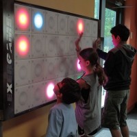
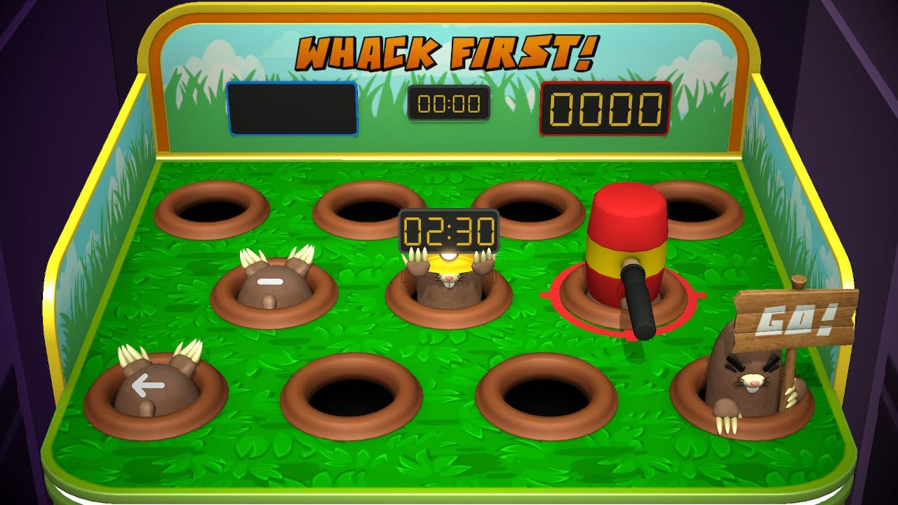
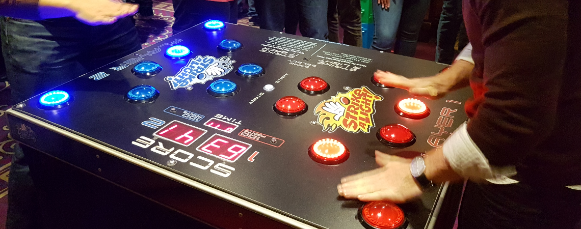
The project draws inspiration from classic arcade games like Whack-a-Mole, where players must react in time to hit the mole. It’s also inspired by the Strike-A-Light reaction game, which emphasizes quick reflexes and precise button presses, and the Interactive T-Wall, which uses a grid-based system to create engaging gameplay. These games inspired me to create something that combines physical action with real-time feedback while adding a personal twist to the football theme.

Wall Active Game « Product categories «
T-WALL
Whack-a-mole - FineProxy Glossary
WHACK A MOLE
Strike a Light - Altitude Events
STRIKE-A-LIGHT

This project is personal because it combines my passion for football with the technical skills I’ve been learning. By adapting the ideas behind arcade games and combining them with the theme of football, I was able to create something exciting and interactive. The result is a challenging and fun game, capturing the essence of football while incorporating creative design and technical elements.

How It Works

In Goal Rush, the physical setup consists of six buttons arranged in a semi-circle, similar to how a ball might travel to different parts of a goalpost during a penalty kick. Above each button is an LED that lights up to signal where the ball is “shot.” The player, acting as the goalkeeper, must press the corresponding button to make the save. If they react quickly enough and press the right button, the Arduino sends a signal to the p5.js display, where the digital goalkeeper dives to block the ball. The ball goes into the net if the player misses or presses the wrong button.

The p5.js display mirrors the physical setup with a goalpost and a goalkeeper. It shows the outcome of each attempt, whether the shot was saved or scored. The game keeps track of the player’s score, rewarding saves and displaying a missed goal animation for failed attempts. The game starts off at a steady speed but becomes faster as it progresses, challenging the player’s reflexes and ability to stay focused.

The objective is to save as many goals as possible before the timer runs out. The combination of tactile button presses and real-time visual feedback creates an experience that captures the tension and excitement of a penalty shootout.

WEEK 10 – Radio

CONCEPT:

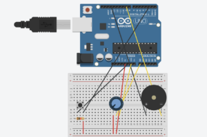
While brainstorming project ideas with Noura, we thought about how a radio works and decided it would be fun to make a simple version ourselves. Our goal was to create an Arduino “radio” that lets you switch between different songs, similar to tuning a real radio. We used a knob as the channel switch, allowing us to choose between three different songs that we got from Github and the exercises we did in class. Each channel has its own song, and turning the knob instantly switches to the next song, giving it a real radio-like feel. We also added a button that acts as a power switch to turn the radio on and off. This way, pressing the button starts the radio, and pressing it again turns it off. We even added a feature so that any song stops playing immediately when the channel changes, so you don’t have to wait for a song to finish before switching to a new one.

HOW IT WORKS:

SETUP:


HIGHIGHT:

The part Noura and I are most proud of is getting the button to work smoothly with the debounce feature. At first, the button would trigger multiple times with a single press, turning the radio on and off too quickly. By adding a debounce function, we made sure the button only registers one press at a time, making it much more reliable. A former student in IM (Shereena) helped us understand how debounce works and guided us in fixing this issue, explaining how it makes the button’s response stable and accurate.

Here’s a snippet of the debounce code we used:

// Variables for debounce
int buttonState;          // Current state of the button
int lastButtonState = LOW; // Previous state of the button
unsigned long lastDebounceTime = 0; // Last time the button state changed
unsigned long debounceDelay = 50;   // Debounce time in milliseconds

void loop() {
  int reading = digitalRead(buttonPin);

  // Check if the button state has changed
  if (reading != lastButtonState) {
    lastDebounceTime = millis();  // Reset debounce timer
  }

  // If enough time has passed, check if the button is pressed
  if ((millis() - lastDebounceTime) > debounceDelay) {
    if (reading != buttonState) {
      buttonState = reading;
      if (buttonState == HIGH) {
        radioState = !radioState;  // Toggle radio on/off
      }
    }
  }

  lastButtonState = reading;
}

This debounce function prevents accidental multiple triggers, making the button interaction smoother. We’re also proud of how the radio switches songs instantly when we turn the knob, making it feel real.

REFLECTION:

Working on this project with Noura was a nice experience, as we got to share our thoughts and class experience by working together. One of our main struggles was making the button work without triggering multiple times, which led us to use debounce for stability. While adding Debounce solved the problem, in the future, we’d like to explore other ways to troubleshoot and fix issues like this without relying on debugging alone.

For future improvements, we’d like to add more interactive features, such as volume control with an additional knob and possibly a small speaker for clearer sound. We could also include more “channels” with various songs or sound effects, giving users a richer experience. Another idea is to add an LED indicator that lights up when the radio is on and changes brightness with volume, making the design even more engaging. These changes would make our project more realistic for a radio and enhance.

CODE:

https://github.com/nouraalhosani/Intro-to-IM/blob/426c7d58639035c7822a4508f2e62dab34db0695/Radio.ino


READING WEEK – 10

Reading the rant, it made me realize how much we’ve settled for touchscreens as our main way of interacting with technology. Sure, they’re easy to use, but I think they’re holding us back from something much richer. Kids today are glued to screens, swiping and tapping all day, and I feel like it’s making them “finger-blind.”. They’re losing the chance to understand the world through real touch. Instead of feeling textures and weights, they’re just seeing everything through glass. In my opinion, that’s robbing them of a huge part of learning and growing.

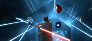
And it’s not just kids. Even for adults, I feel like we’re missing out on deeper connections with tech. Take virtual reality games. Everyone loves the visuals, but games like Beat Saber feel empty to me without any sense of touch or resistance. It’s a hollow experience, one that relies only on what we see, not what we feel. I think this disconnect leaves us with flashy visuals but no real engagement.

Beat Saber – VR

In addition, I also think that the obsession with brain-computer interfaces is just as disappointing. Sure, it sounds futuristic, but I think it’s actually a step back. The idea of controlling things with thoughts alone ignores the importance of our bodies. We’re already sitting at screens too much, and this just pushes us deeper into that immobility. I believe technology should encourage movement and real interaction, not trap us in a still, disconnected state.

“Pictures Under Glass” sums up the issue perfectly. It’s like we’re numbing one of our most powerful senses for convenience. When I pick up a book or a glass, my hands get all kinds of feedback from weight, texture, and balance. But with a screen? Nothing. Even something as simple as making a sandwich taps into a level of interaction that a screen can’t touch. In my view, designers need to stop treating screens as the final answer and start creating tech that actually respects our bodies’ abilities.

WEEK 9 – traffic light

CONCEPT:

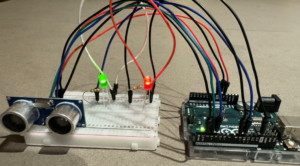
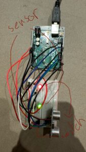
For my project, I’ll be creating a traffic light system. I got the idea for this project while driving, and I thought it would be interesting to implement this concept in my work by creating a sensor that reacts like a traffic light. My goal is to create a system that changes based on a car’s distance from the light, just like real traffic signals. I’ll use an ultrasonic sensor to detect the car’s proximity and control two LEDs: one red and one green.

In my code, I’ll program the red LED to start dim and gradually get brighter as the car gets closer, signaling the car to slow down and stop. When the car reaches a specific point, I’ll use a switch in the code to light up the green LED, showing that it’s safe for the car to proceed. This setup uses the sensor data to adjust the brightness of the red LED, while the switch allows for an easy transition to the green light, creating a basic but effective interactive traffic light system.

SETUP:

VIDEO DEMONSTARTION:

IMG_1442

HIGHLIGHT:

The part of my code I was really proud of was when I filled out the mapping and measuring distance while setting the LED brightness and figuring out a way to debug the code as it kept getting corrupted. This code snippet measures distance using an ultrasonic sensor and adjusts an LED’s brightness based on how close an object is. First, ‘pulseIn(echoPin, HIGH);’ measures the time for a sound wave to travel to an object and return, which I convert to centimeters using ‘int distance = duration * 0.034 / 2;’. I then map this distance to an LED brightness range (0-255): ‘int brightness = map(distance, 0, 100, 255, 0);’, making the LED brighter as the object gets closer. I use ‘Constrain()’ to keep the brightness within the allowed range. Finally, ‘analogWrite sets the LED brightness based on distance, and’ Serial.print() outputs the values in the serial monitor for easy debugging. This part of the code was a struggle as it was something new; however, with a couple of tries, i got it

// Measure the time it takes for the echo to return
long duration = pulseIn(echoPin, HIGH);

// Calculate the distance in centimeters
int distance = duration * 0.034 / 2; // Speed of sound is ~0.034 cm/us

// Map the distance to LED brightness
int brightness = map(distance, 0, 100, 255, 0); // Closer = brighter, max distance = dim
brightness = constrain(brightness, 0, 255);     // Keep brightness within 0-255

// Set the brightness of the distance LED
analogWrite(distanceLedPin, brightness);

// Print switch state, distance, and brightness to the Serial Monitor for debugging
Serial.print("Distance: ");
Serial.print(distance);
Serial.print(" cm, LED Brightness: ");
Serial.println(brightness);

CODE:

arduino file

REFLECTION:

For future improvements, I would like to add a yellow LED to create a full traffic light sequence, transitioning smoothly from red to green, with a yellow warning light in between. I also noticed that the brightness adjustment could be more gradual, so tuning the mapping range would improve the overall responsiveness.

RESOURCES:

https://projecthub.arduino.cc/Isaac100/getting-started-with-the-hc-sr04-ultrasonic-sensor-7cabe1


READING #WEEK 9

“Making Interactive Art: Set the Stage, Then Shut Up and Listen” by Tom Igoe was an interesting look at interactive art. It seemed like Igoe’s advice to not over-explain our work and let viewers make up their own minds about it was trying to say that art can be more than just a one-way statement. For instance, by letting people interact without being told what to do, we’re having them finish the piece through their own experiences.

This made me think of Yayoi Kusama’s “The Obliteration Room.” Igoe said that art is like directing players; the artist sets the scene but doesn’t control every action. Kusama makes a room that is all white and tells people to cover it with colorful dot stickers in any way they want. She doesn’t tell them where or how to put the dots; the audience is the only one who can change the room. It turns into a lively group work over time, with each person’s choices shaping it. I felt that this example was like Igoe’s concept of stepping back and letting go, allowing people to experience art in their own way.

This concept of letting go and allowing for freedom in interpretation also ties into Igoe’s approach in “Physical Computing’s Greatest Hits (and Misses)”. Here, he similarly emphasizes the value of exploring foundational themes and encourages creativity without fear of being unoriginal. Rather than chasing entirely new ideas, he urges creators to build upon recurring themes in physical computing, adding their own twist.

What I liked about this example was the “theremin like instruments.” It says that even though making a simple theremin is fun, it doesn’t always allow for useful interaction. This example showed me that even though the projects are easy, they can still push the people who make them to think beyond the basics and look for ways to give the interaction more meaning. Whether in art or software, I think both readings support the idea that effective interactive work emerges when the author takes a backseat, encourages individual interaction, and has faith in the audience to realize their interpretations.