
//Add abigails links
For this assignment we started by building the circuit for each part and made a circuit that would work for all of them.
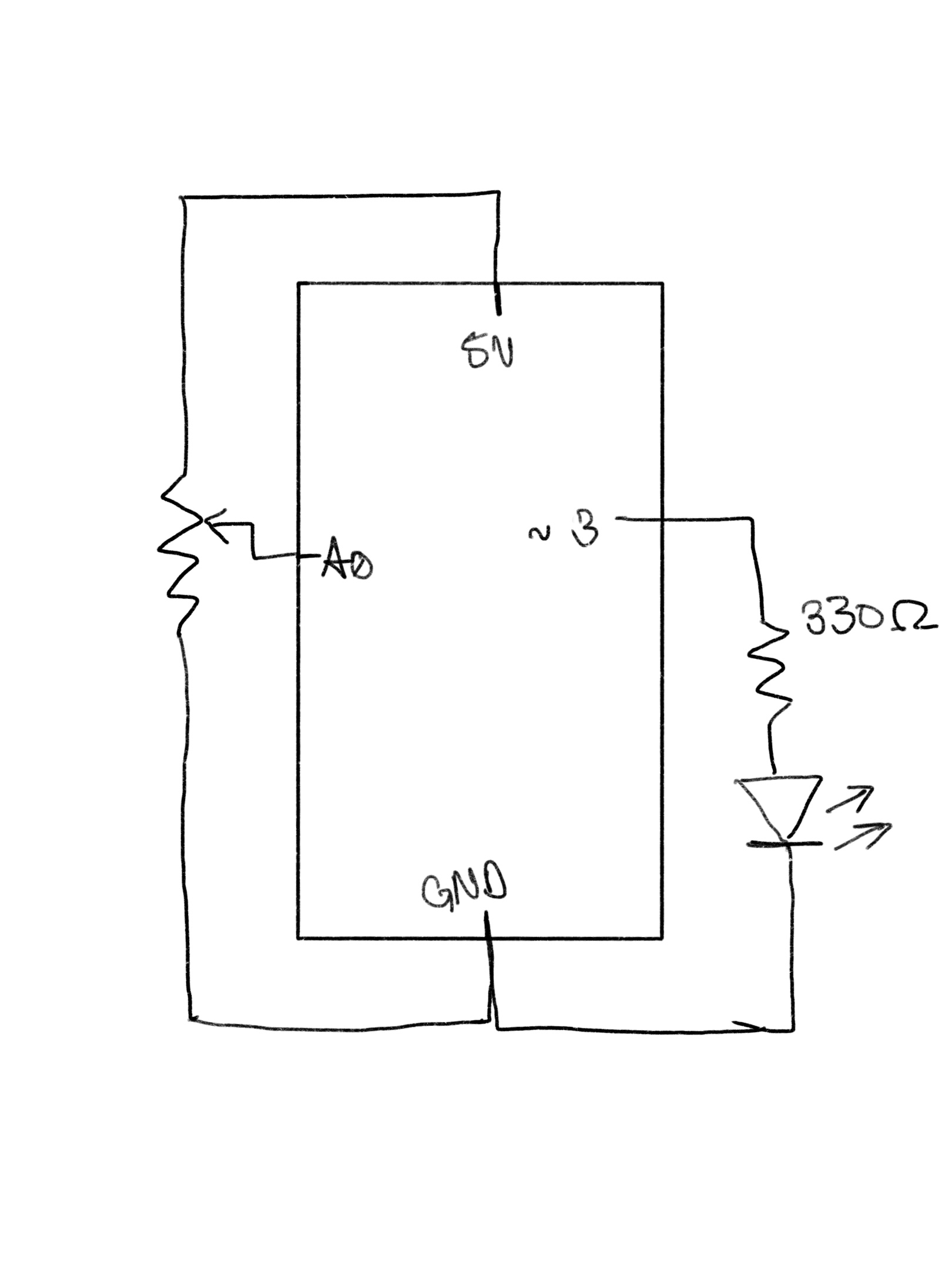
Circuit:
Part 1:
For the first part of the assignment we took inspiration from the following website to figure out an efficient way to complete the task:
Serial Input to P5.js Using the p5.serialport library
Instead of using the potentiometer to move around an ellipse, we decided to make it move around a ufo around on a background instead:

We ran into a delay problem that would make the ufo glitch around instead of moving smoothly so we figured out the optimal delay rate:
Serial.write(mappedPot);
//Serial.println(mappedPot);
// slight delay to stabilize the ADC:
delay(200);
Also during this exercise, we started experiencing disconnection issues where the Arduino and p5js would stop communication, give erratic readings or get stuck at values (170, 20, 13, and 0). After a lot of head-scratching our fix was:
Restart the computer.
By using the mapped data received directly from the Arduino we were able to move the ufo around easily:
image(ufo, inData, 150,50,30)
Part 2:
For part 2 of the assignment, we wanted to create a slider on p5js that could control the brightness of the LED as we felt it was the most intuitive way of showing light levels.
We took some coding inspiration from the following Youtube tutorial in some places:
p5.js and Arduino serial communication – control an Arduino from p5js
We made it so the slider had a length of 255 and the interval at which the bar moved was + or – 5. This allowed us to do this without including the map() function to map the values to a range of 0 to 255.
// making the slider in setup function
slider = createSlider(0, 255, 10, 5);
slider.position(50, 200);
slider.style('width', '200px');
textSize(14)
text("Use the slider to adjust brightness of the LED:", 8, 150)
outByte = slider.value()
serial.write(outByte);
Also, to make the p5js part even more interactive we added a bit of code to change the background of the canvas which made it go from a dark shade of red on lower outData() values to match the brightness of the LED.
background(outByte,0,0);
fill(255);
On the Arduino side of things we simply used the digitalWrite() function to turn on the LED and update the output values by using the following bit of code:
   digitalWrite(LED_BUILTIN, HIGH); // led on while receiving data

   int light = Serial.read();
   Serial.println(light);
Part 3:
For this part of the project we wanted to edit the code provided to make the ball fall slower because of air resistance but later we decided to add the sideways wind functionality because the ball was not slowing down noticeably.
For controlling the direction and magnitude of the wind we decided to use a potentiometer that was mapped to output values between 0 and 255.
int mappedPotentiometer = map(analogRead(potentiometer), 0, 1023, 0, 255);
Serial.write(mappedPotentiometer);
The direction of the wind on either axes could be altered using the following code in p5js:
// change wind direction
windStrength = 5;
newWindDirection = map(inData, 0, 255, -windStrength, windStrength);
wind.y = newWindDirection;  // make ball fall slower
wind.x = newWindDirection;  // make ball move on the horizontal axis
We noticed that there was a delay between the ball hitting and the LED on the circuit lighting up so we made the background change colors every time the ball hit the bottom of the screen to give us visual feedback of what we were looking at:
background(backgroundShade, 0, 10);

//where the value of backgroundShade updates everytime the ball hits the ground using //the following bit of code:
// if (positionOfBall.y > height - mass/2 - mass) {
//backgroundShade = backgroundShade + 5
//}
Video: