
Google Drive Link: https://drive.google.com/file/d/1_hd31ynpr4AzkeD99QR3nakPaNJlEiRF/view?usp=sharing
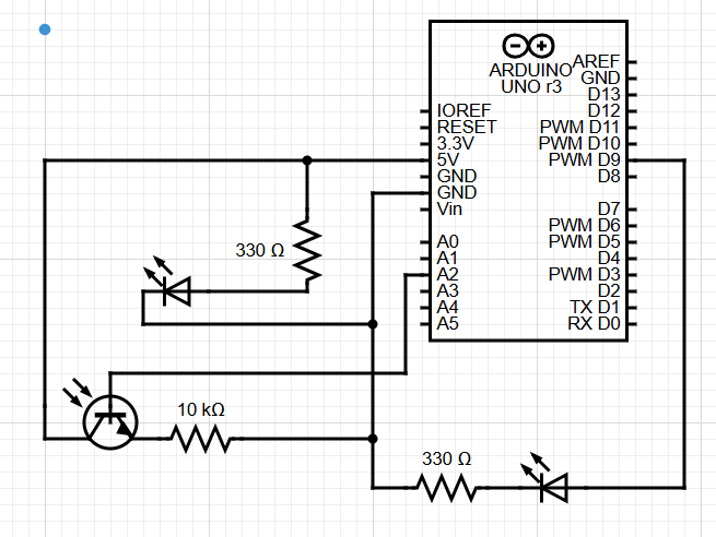
My idea for this assignment was to have a light that would automatically turn on when it was dark in the room while the other light could be manually turned on. Kind of like a smart light vs a regular light switch light. To do this is use the photoresistor to get the values of the brightness in the room and coded the arduino such that under a certain threshold, the light would automatically turn on.
The circuit diagram looked like this:
The code for it can be seen here:
const int LED_PIN = 9;
const int LIGHT_THRESHOLD = 500;
// the setup routine runs once when you press reset:
void setup() {
  // initialize serial communication at 9600 bits per second:
  pinMode(LED_PIN, OUTPUT);
  Serial.begin(9600);
}

// the loop routine runs over and over again forever:
void loop() {
  // read the input on analog pin
  int sensorValue = analogRead(A2);
  // print out the value you read:
  Serial.println(sensorValue);
  delay(1);  // delay in between reads for stability
  if (sensorValue < LIGHT_THRESHOLD) { //codes the light to turn on when brightness is low
    digitalWrite(LED_PIN, HIGH);
  } else {
    digitalWrite(LED_PIN, LOW);
  }
  delay(100);
}
Overall, it wasn’t too difficult. I just struggled a bit with getting the wires in the correct places and accidentally blew a light because the resistor wasn’t plugged in all the way. It’s tricky dealing with so many wires on the board, I wish it could look more streamlined.