
Initial Idea
The goal of this project was to explore the interaction between analog and digital sensors and how they can be used to control outputs creatively. Specifically, the task was to use at least one analog sensor and one digital sensor to control two LEDs, one through digital means (on/off) and the other through analog means (brightness control). The initial idea was to keep the components simple but effective: a push-button as a digital switch and a potentiometer as an analog input, controlling a red and green LED, respectively.
Execution
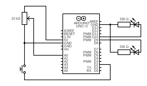
The red LED was connected in series with a 330-ohm resistor and controlled by a push-button, which toggled it on or off based on the button state. The green LED was also connected with a 330-ohm resistor and its brightness was adjusted using a 10k potentiometer wired to an analog input pin. The analog value was read from the potentiometer and mapped to a PWM value to vary the green LED’s brightness.
Here is a diagram:
const int potPin = A0;
const int buttonPin = 2;
const int ledDigital = 10;
const int ledAnalog = 9;

bool ledState = false;

void setup() {
  pinMode(buttonPin, INPUT_PULLUP); // button active LOW
  pinMode(ledDigital, OUTPUT);
  pinMode(ledAnalog, OUTPUT);
}

void loop() {
  // Read potentiometer value
  int potValue = analogRead(potPin); // 0 - 1023

  // Map it to PWM range
  int brightness = map(potValue, 0, 1023, 0, 255);
  analogWrite(ledAnalog, brightness);

  // Read button
  if (digitalRead(buttonPin) == LOW) {
    delay(200); // debounce
    ledState = !ledState;
    digitalWrite(ledDigital, ledState);
  }

  delay(50); // loop delay
}
Highlights
-
The logic worked exactly as planned: the button cleanly toggled the red LED, and the potentiometer provided smooth brightness control for the green LED.
-
The circuit was clean, and the schematic clearly represents the wiring and design intent.
-
I’m proud of how the components were chosen and integrated in a way that’s both simple and pedagogically effective, perfect for demonstrating basic input/output handling on Arduino.
What Could Be Improved
-
Debouncing the push-button in code could be refined further to prevent unintended toggles.
-
A creative twist (e.g., combining analog and digital inputs for more complex LED behaviors or using a different type of analog sensor like an LDR) could elevate the interactivity.
-
Next time, I might also add a small OLED screen or serial output for live feedback on sensor values for better debugging and visualization.