Concept
When thinking about concept of my project, I decided to use a light sensor for controlling LEDs in an analogue fashion. I thought initially about making it as an interactive artwork, where the brightness of many LEDs will be controlled by the lighting of the room and the way the users manage light sensors themselves. However that idea didn’t work, because I made a mistake of connecting wires to wrong digital inputs (without PWM~), which led to unsuccessful fading of the LEDs. I realized my mistake too late, and already had switched my idea to something more fun and engaging. As lights were just switching on and off when I covered the light sensor with my finger, it reminded me of DJ Set where you press specific buttons and different sounds occur. I decided to do the same, but replacing sounds with LEDs. I had three LEDs that would be lighted using light sensors. And I also included an LED that was switched on using slide switch, to add digital inputs to the circuit, since light sensors were connected to analog inputs.
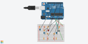
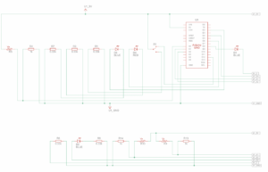
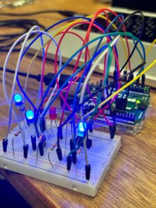
Arduino Setup
As you can see, I just followed the rhythm of the song with my DJ Set.
Highlight of the code
int sensorValue = analogRead (A0);
Serial.println (sensorValue);
sensorValue = constrain (sensorValue, 10,200);
brightness = map (sensorValue, 15, 140, 0, 255);
analogWrite (ledPin2, brightness);
delay (10);

int sensorValue2 = analogRead (A1);
sensorValue2 = constrain (sensorValue2, 10,200);
brightness1 = map (sensorValue2, 15, 140, 0, 255);
analogWrite (ledPin3, brightness1);
delay (10);

int sensorValue3 = analogRead (A2);
sensorValue3 = constrain (sensorValue3, 10,200);
brightness2 = map (sensorValue3, 15, 140, 0, 255);
analogWrite (ledPin4, brightness2);
delay (10);
I think the hardest part of the coding was just with assigning correct numbers and pins to each function. I decided to use “constrain” and “map” functions that we learned on our lesson, because when building my project in IM Lab I found the light sensor values on Serial Monitor vary only from 15 to 140, hence I mapped them to 255 range, so that brightness could be manipulated. As it can be seen from the Arduino setup and the video, there are a lot of wires on the breadboard, which was another challenge of connecting them just right and not fail the code.
Reflection
In my next improvements of the project, I wish to experiment with different types of sensors, such as temperature, ultrasonic and sound sensors. It would give my project higher difficulty and also interest. Also, I am very eager to learn and employ Piezo Speaker in my next projects, as a further development of the DJ set. Moreover, it would make sense if I would use bigger breadboard and make connections more clear, reducing unnecessary wires. I would also want to connect RGB LED, as it gives higher flexibility and room for experimentation.


