Concept
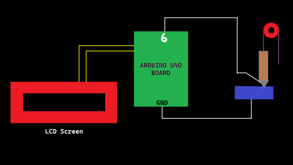
This assignment is the most unique one as at the most basic level, we had to utilize the physical systems around us to make or break a circuit. That’s why I decided to use an everyday tool- the pulley to control the flow of electricity. Rather than pressing a button or flipping a switch, the user plays a more active role in balancing forces. The switch itself is a rotating beam with a conducting end, which is lifted or dropped through a pulley mechanism onto a conductive plate. By carefully adding or removing weights, the user must balance or offset gravity to either make or break the connection. A simple two dimensional diagram of the same looks like this:
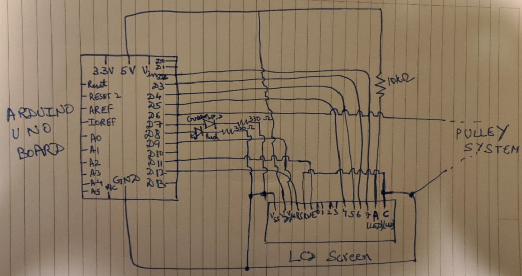
And the circuit schematic is:
The Physics behind it
When the weight of the external weights added create enough torque to lift the heavy end of the beam, the lighter end of the beam (the one having the conducting pin), moves down to touch the conducting plate, completing the circuit and prompting the “LOW” state (because of the Pullup Input).
This state is pivotal, as it is needed to switch which LED lights up in the Arduino. Simply put, we use the red LED for stopping the user to add weight in the pan (which is associated to the “HIGH” state of the switch) and green LED to continue adding the weights (which is associated to the “LOW” state of the switch).
Thus, the Gravity Switch, which uses a Simple Pulley mechanism, Physics and Arduino actualy behaves as a “Toggle Switch,” but we don’t user our hands in a direct way. We simply rely on Gravity to do the connecting part for us.
Code Implementation
The only library imported was the LCD Library “Liquid Crystal.h”.
Now, according to the code:
// Including the required libraries
# include <LiquidCrystal.h>

// Initialize the library with the numbers of the interface pins
LiquidCrystal lcd(12, 11, 5, 4, 3, 2);
const int contrast = 90;
const int contrastPin = 9;

// Defining the Global Variables
// Defining the LED pins
const int redLEDPin = 8;     // Pin used for reading the state of the switch of Red LED
const int greenLEDPin = 7;   // Pin used for reading the state of the switch of Green LED

// Defining the switch pin
const int switchPin = 6;     // Pin used for reading the switch state to decide which LED lights up
int switchState;
int previousSwitchState = -1;

// Setup Function
void setup() {
  // Setting the Pin to Input to read its state
  pinMode(redLEDPin, OUTPUT);
  pinMode(greenLEDPin, OUTPUT);
  pinMode(switchPin, INPUT_PULLUP);

  // Initialize the LCD and set up the columns and rows
  lcd.begin(16, 2);
  delay(500);

  // Setting up the contrast for LCD Display as not using Potentiommeter
  analogWrite(contrastPin, contrast);
  Serial.begin(9600);
}

// Loop Function
void loop() {
  switchState = digitalRead(switchPin);

  // Only clear and update the LCD when the switch state changes
  if (switchState != previousSwitchState) {
    lcd.clear();  // Clear the screen only when the state changes

    if (switchState == LOW) {
      lcd.setCursor(0, 0);
      lcd.print("Switch is ON.");
      lcd.setCursor(0, 1);
      lcd.print("Add more weight!");

      Serial.println("SWITCH STATE IS HIGH ");
      digitalWrite(greenLEDPin, HIGH);
      digitalWrite(redLEDPin, LOW);
    }

    else {
      lcd.setCursor(0, 0);
      lcd.print("Switch is OFF.");
      lcd.setCursor(0, 1);
      lcd.print("HALT THE WEIGHTS");

      Serial.println("SWITCH STATE IS LOW");
      digitalWrite(redLEDPin, HIGH);
      digitalWrite(greenLEDPin, LOW);
    }

    previousSwitchState = switchState;  // Update the previous state
  }

  delay(100);
}
In the code, I have used the pins 2, 3, 4, 5, 11 and 12 for the D4, D5, D6, D7, Enable, and RS pin on the LCD Display. I have used a fixed 10k Ohm resistor instead of the potentiometer for the contrast level (As we don’t want to use our hands directly in any part of the project).
Also, Pin 6 is the main switch pin which is responsible for reading the state, and the entire circuit (+ LCD) behaves according to the state.
Head Scracthing Software Problems faced
In communicating with the LCD Screen, some problems were faced, notably the random toggling of the switch input when it was not connected. This was caused by a floating input pin – a common issue in digital electronics. A floating pin picks up electrical noise, resulting in irregular behavior. The solution involved enabling the internal pull-up resistor using “INPUT_PULLUP” on the switch pin. This ensures that the switch pin has a default state of HIGH when not pressed, making the input stable and reliable. (I got to know about this from the Arduino Forum: https://forum.arduino.cc/t/arduino-input-seems-to-be-randomly-toggling/448151)
Another issue was the LCD displaying random characters in a flow instead of the expected text. This issue had multiple causes: frequent clearing of the display, incorrect contrast settings, and potential timing issues during initialization. The frequent use of lcd.clear() in every loop iteration was causing the screen to flicker and show inconsistent outputs. By refactoring the code to only clear the LCD when the switch state changed, the display became stable and only updated when necessary, improving both performance and readability.
Demonstration Video
Problems associated
- If the user puts too weight, the beam or the conducting pin can bend or break, which will make the circuit useless.
- One can also lift the beam by themselves to make the pin touch the conducting plate, but that defeats the purpose of the assignment.
- I also wanted a smaller more heavier block which has the Pin 6 installed as the main weight, but the closest I could get was that block in the demonstration video.
- I wanted to use the Slot weights like these:
which are typically used in Physics experiments (but I could not find them anywhere *sad noises*)


