Overview Video Link
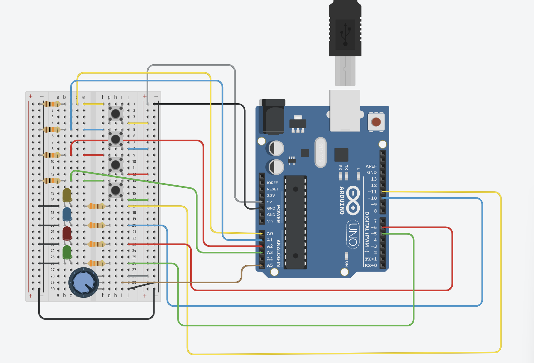
The production goal for this week was to understand and play with the analog and digital components in the kit. Then with the input of the components, apply the readings to at least two LED bulbs. Just for fun, I decided to use 4 because I wanted them to glow in a random pattern with varying brightness. With the potentiometer, I decided to showcase how it can be linked to multiple LEDs to control their brightness.
Difficulty and Success of the Process
I felt the most difficult part of the process was the coding and software. Alongside getting use to the IDE, I think connecting the wires to the correct input ports and then referencing the port in the code was a bit confusing to me. Since some of the input ports on the Arduino do not have Pulse Width Modulation (PWM) that converts digital inputs into analog results, I initially was connecting leads to port 13 that didn’t have PWM functionality resulting in my LED blinking when I didn’t want them to and other fault design. With a quick Google search, it seemed like pins 3,5,6,9,10,11 have PWM functionality and changing my routing to those pins resolved most of my issues. As such, my recommendation for others starting out is to use those pins when working with analog measurements while using digital components.
On the other hand, I found great success in connecting multiple LEDs on my breadboard and then connecting the various parts in the IDE. I had a lot of fun organizing and visualizing the routing and see how each of the components would work together. I really loved how the random pattern turned out, but I think in the future I would like to find a way to connect the brightness control with the pattern. With the potentiometer, I ended up connecting each individual light with the meter, but not when the pattern was being displayed. I also wished I had more buttons to play around as well. However, I am still happy with the overall design and look forward to future projects.
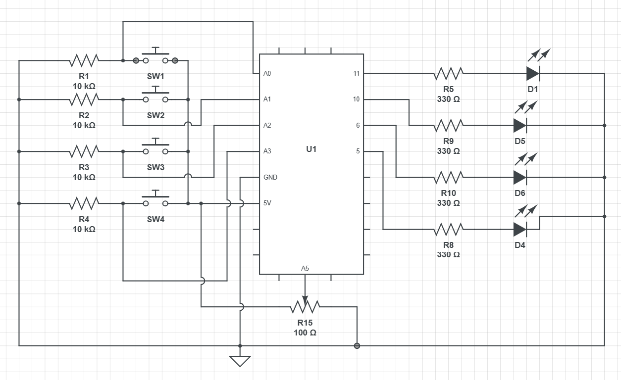
Schematic (TinkerCAD)
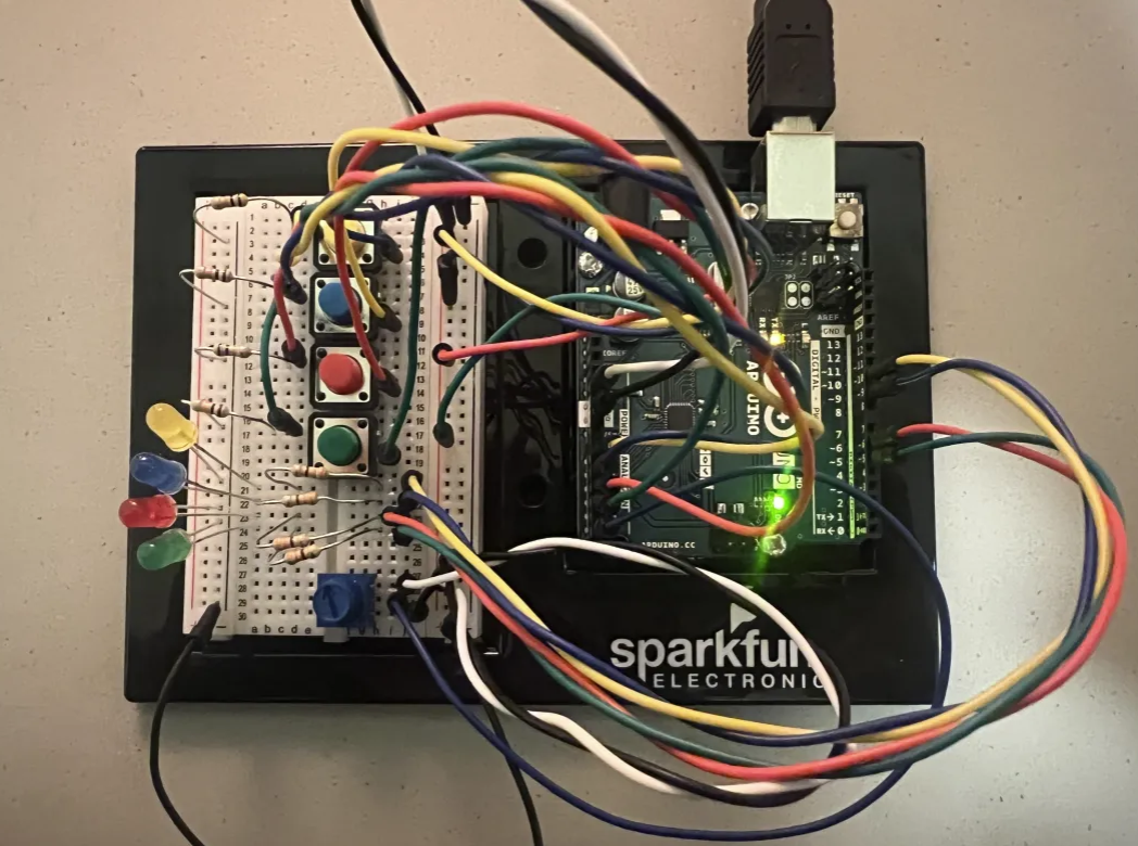
IRL Photo


