intro
How tough can designing a switch be? Presumably not much—but it’s the contrary. While the circuit to utilize a switch may be one of the simplest ones in the electronics world, to what extent can that switch ‘make sense’ as well as be creative and ergonomically intuitive? From the distance-triggered switch I rushed in class to a coin-classifier that utilizes the different diameters of different coins, both of these prototypes I made in the course seem too ‘basic’ in terms of being so realistic (aka. boring). At the end of the day, setting off from the concept of ‘using body parts,’ I came up with the idea of a ‘Sleepiness Detector’ that would act as an automatic alarm (visually with LEDs and sonically with a buzzar) when the user (if there is one) closes their eyes.
process
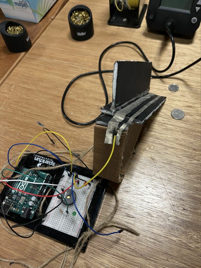
Although the first two prototypes are discarded, I would still give credit to them here as a chronicle:
Still, the second prototype did give me some inspiration about using the conductive fabric to form the later artificial eyelids. While the code below is relatively simple, I would say the most difficult part of this product is to ‘install’ artificial eyelids to my eyes—maybe this is where collaboration was a necessity.
/*
+---------+               +--------+
| Switch  |  eyes         | LED R  |
|         |               |        |
| Terminal|--- Pin 2 ---  | Anode  |--- Pin 9 (Arduino)
|         |               |        |
| Terminal|--- GND        | Cathode|--- GND (through 220Ω resistor)
+---------+               +--------+

                         +--------+
                         | LED G  |
                         |        |
                         | Anode  |--- Pin 10 (Arduino)
                         |        |
                         | Cathode|--- GND (through 220Ω resistor)
                         +--------+

                         +---------+
                         | Buzzer  |
                         |         |
                         | Positive|--- Pin 11 (Arduino)
                         |         |
                         | Negative|--- GND
                         +---------+
*/

#define SWITCH_PIN 2   // Pin connected to the switch
#define RED_LED_PIN 9  // Pin connected to the red LED
#define GREEN_LED_PIN 10 // Pin connected to the green LED
#define BUZZER_PIN 11   // Pin connected to the buzzer

void setup() {
    pinMode(SWITCH_PIN, INPUT_PULLUP); // Set switch pin as input with pull-up resistor
    pinMode(RED_LED_PIN, OUTPUT);       // Set red LED pin as output
    pinMode(GREEN_LED_PIN, OUTPUT);     // Set green LED pin as output
    pinMode(BUZZER_PIN, OUTPUT);        // Set buzzer pin as output
}

void loop() {
    // Read the state of the switch
    int switchState = digitalRead(SWITCH_PIN);

    if (switchState == LOW) { // Switch is ON (active low)
        digitalWrite(RED_LED_PIN, LOW);      // Turn off the red LED
        digitalWrite(GREEN_LED_PIN, HIGH);   // Turn on the green LED
        tone(BUZZER_PIN, 1000);              // Play sound at 1000 Hz
    } else { // Switch is OFF
        digitalWrite(RED_LED_PIN, HIGH);     // Turn on the red LED
        digitalWrite(GREEN_LED_PIN, LOW);    // Turn off the green LED
        noTone(BUZZER_PIN);                   // Turn off the buzzer
    }
}
schematics & illustration
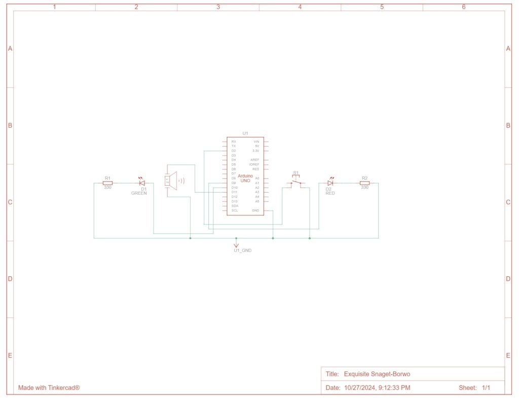
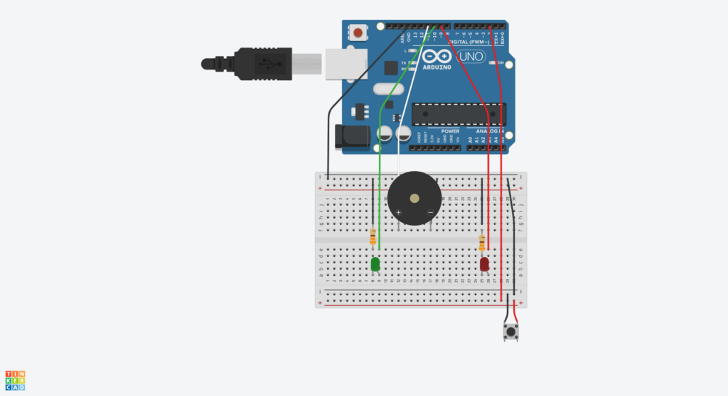
Both of the graphs are generated with TinkerCAD
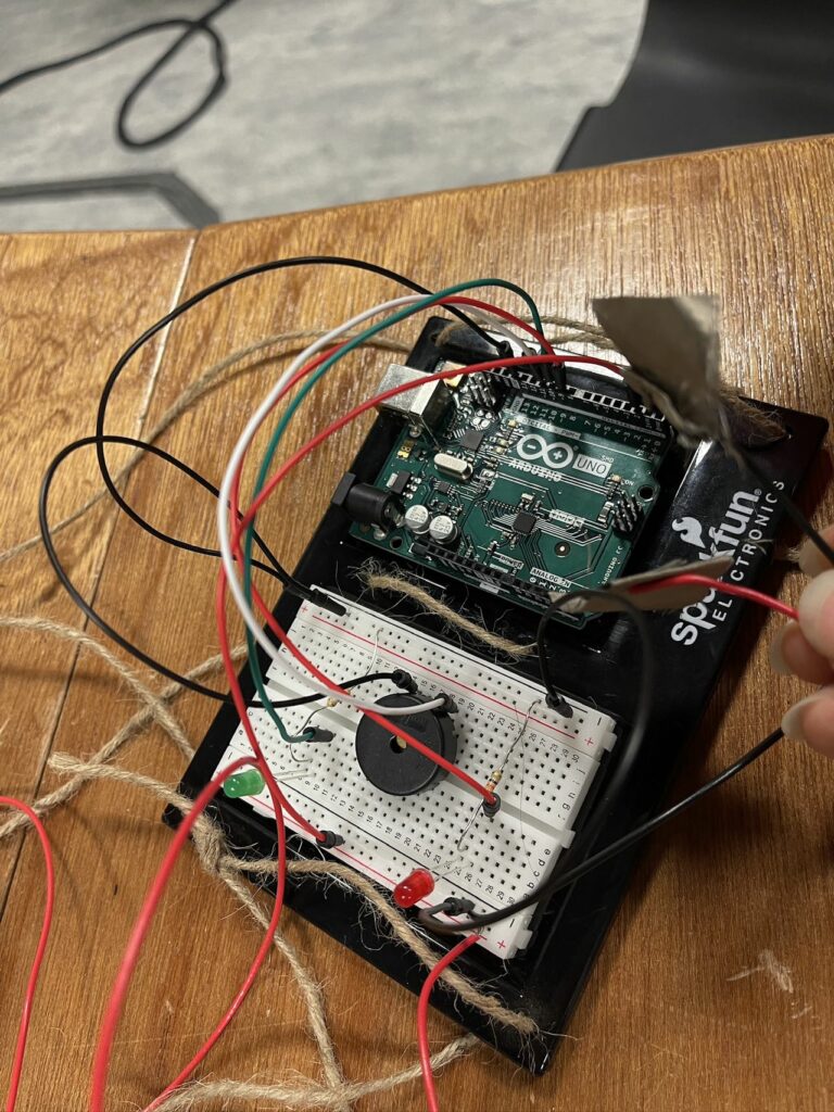
Product Demo
Hindsight
Obviously, the method I used to install eyelids was not wise enough to replicate easily. If this is actually to be a thing, then there must be some more mature way to detect if eyes are closed.


