My concept and inspiration for the final project came from a wish to make something related to cameras/photo-taking/film. Initially, I wanted to make a “camera on wheels”, but then I realized the camera lens would be on my laptop and therefore couldn’t add wheels to it, haha. So, I changed my idea but stuck with the camera concept.
I really enjoy taking photo booth pictures. In fact, I will always push my friends to take them with me if I see a photo booth anywhere. I have collected these grid images from all around the world – Beirut, Abu Dhabi, Paris, New York, Madrid, London, Dubai… And I still have them all saved. They are, to me, a beautiful way of keeping memories in a non-digital fashion, which we tend to towards these days with our phones. I also enjoy the photo booth app on the phone, but the grid layout that results is not the same as a typical, “retro” photo booth.
So, I decided to create a photo booth, which generates four images as a vertical grid!
How to use it
This project is composed of two parts: my laptop with a p5 sketch, and a “camera” I built out of cardboard, inside which there is the Arduino and breadboard. The p5 sketch begins with a start page, that states “photo booth”. There are also instructions: the first step is to click on the screen (when the images are downloaded, the user needs to press on the screen to return to the chrome page); the second step is to press record on the camera to start taking the images.
Once the record button on the camera is pressed, a message is sent from Arduino to p5 to start the photo booth session. Simultaneously, a LED turns on for 20 seconds (which is the length of each session). The four images are taken at five second intervals, with a countdown starting at three seconds. After the twenty seconds have passed, the images are downloaded as a grid, and the user can airdrop it to their phone. Moreover, when the images are done, the start page is displayed again.
Codes
To achieve this, I created a short code on Arduino and a longer one on p5.
Arduino code & circuit
const int BUTTON_PIN = 2;
const int LED_PIN = 13;

bool ledState = false;
int lastButtonState = LOW;
unsigned long startTime = 0; // variable to store the time the button was pressed
const unsigned long interval = 20000; // interval of 20 seconds to indicate when the LED must turn off

void setup() {
  pinMode(BUTTON_PIN, INPUT);
  pinMode(LED_PIN, OUTPUT);
  Serial.begin(9600);
}

void loop() {
  int reading = digitalRead(BUTTON_PIN);

  // checking if the button was pressed
  if (reading != lastButtonState) {
    lastButtonState = reading;
    if (reading == HIGH) {

      ledState = true; // turn LED on
      digitalWrite(LED_PIN, HIGH);
      Serial.println("START"); // send "START" to p5
      startTime = millis(); // start recording the time of button press
    }
  }

  // checking if 20 seconds have passed since the button was pressed
  if (ledState && (millis() - startTime >= interval)) {
    ledState = false; // turn LED off
    digitalWrite(LED_PIN, LOW);
    Serial.println("STOP"); // when 20 seconds have passed, send "STOP" to p5
  }
}
p5 code snippets
→ a function to start the countdown between each image.
function startCountdown() {
  countdownValue = 4; // start the countdown with "nothing"
  clearInterval(countdownTimer); // clear the existing timer, necessary after the first image is taken after the sketch is played
  countdownTimer = setInterval(() => {
    countdownValue--;
    if (countdownValue === 0) {
      // when count is down to 0
      clearInterval(countdownTimer); // stopping the timer
      captureImage(); // capturing an image after the countdown
      countdownValue = 4; // resetting the countdown value back to 4
      setTimeout(startCountdown, interval); // 1-second delay before restarting the countdown
    }
  }, interval); // repeat the function at 1-second intervals
}
→ a function to capture and save the images, with a sound that plays when each image is taken.
function captureImage() {
  if (recording) {
    sound1.play(); // playing the sound when an image is captured

    images[captureIndex] = videos[captureIndex].get(); // capturing the image from each of the four video feeds
    captureIndex++;

    // when the four images are taken, recording is stopped and images are saved as a grid
    if (captureIndex >= 4) {
      stopRecording();
      saveImages();
    }
  }
}
→ determining the countdown value which is then displayed (3, 2, 1 only).
→ function to start recording, which is later activated when the button of the camera is pressed, in a “START” state.
function startRecording() {
  if (!recording) {
    recording = true;
    captureIndex = 0;
    images = [null, null, null, null]; // reset the images array to clear previous session
    clearInterval(countdownTimer); // clear the timer from the previous session

    // clearing the video feeds
    for (let i = 0; i < 4; i++) {
      videos[i].hide(); // hide the video to clear the old feed
      videos[i] = createCapture(VIDEO); // create a new video capture
      videos[i].size(width / 3, height / 3); // set size for each video feed
      videos[i].hide(); // hide the video feed
    }

    startCountdown(); // start the countdown before the first image is captured
  }
}
→ function to stop recording, which is activated by the “STOP” message received by Arduino after the twenty seconds have passed.
// function to stop recording
function stopRecording() {
  print("Recording ended");
  if (recording) {
    recording = false;
    clearInterval(countdownTimer); // clear the countdown timer completely
  }
}
→ function to read the serial data from Arduino.
// read serial data from arduino
function readSerial(data) {
  if (data != null) {
    if (data == "START") { // when data from arduino is "START"
      displayStartPage = false; // switch to the photo booth page
      startRecording(); // start recording
    } else if (data == "STOP") { // when data from arduino is "STOP"
      displayStartPage = true; // display start page
      stopRecording(); // stop recording
    }
  }
}
Sketch
And here is a link to the full screen sketch:
https://editor.p5js.org/alexnajm/full/LVOvvvioq
What I am proud of
I am particularly proud of finally being able to understand how serial communication works. For me, I had a hard time processing it in practice, although in theory it did make sense. Applying it for this project which I made from scratch, as compared to the exercises we did in class, enabled me to better grasp the concept of serial communication.
Additionally, I am proud of how this project has evolved. I had a few ideas in between which truly were not challenging enough. I am not saying that this project is super complex, but it definitely took time and effort to try and understand how everything works in order to achieve this final result.
Challenges
I encountered multiple challenges, first, creating serial communication from scratch. Again, it was a bit hard for me to apply the concepts.
Another challenge was getting the feeds and countdown to reset after each session. At first, the images from the previous session remained on the feeds, which means the user couldn’t see a live version but only the images taken. Gladly, I was able to figure it out – same for the countdown.
Areas for future improvement
Eventually, I would like to create a better design for the p5 sketch. As of now, I feel like it’s a bit… bland.
I would also like to try to incorporate filters, which the user can choose from before taking the images. This was a bit hard as the images cannot be downloaded with the filter, and I did not want the grid to look different than the images displayed on the sketch.
This is a game that seeks to provide engagement via the unknown. That is, a game that uses the concepts of darkness and ghosts. Take, for example, the video game series Five Nights at Freddy’s, whose gameplay loop consists in administrating the energy left in order to prevent the enemies from reaching the protagonist; PhotoGhost is almost the same. In this game, the player has to traverse a dark area that gets filled with ghosts over time, and in order to avoid losing, the player has to fill the battery by going to the battery refill areas. Also, as part of the core gameplay concept, the player can listen to some of the noises that the piezo buzzers make according to the location of the ghost.
Figure 1. Physical component with cover on, while in development.Figure 2. Physical component from a top perspective, while in development.Figure 3. Box finishedFigure 4. Box Finished from a different perspective.
2.2 Pictures of the Arduino set-up
Figure 5. Arduino wiring complete, which is inside the box.
2.3 Pictures of the game in p5.js
Figure 6. TutorialFigure 7. Gameplay, but the lights are turned off.Figure 8. Gameplay, but the lights are turned ON and a ghost is visible.
3. Implementation
3.1. Interaction Design
When the player arrives at the controller, it will be observable that there are:
4 Green buttons placed as a D-PAD.
One white button that is put further away from the rest of the components.
One photoresistor and one blue LED close to each other.
Four piezo buzzers that are coming on different sides: two on the left and two on the right. Each one is located on a different corner.
A hole where the data is sent to the Arduino.
While the visual design is rather basic, it seeks to be portable, easy to read, and comfortable to use.
Basically, what the Arduino code does is the following:
It prepares the assigned pins, and then it waits to receive the communication with p5.js.
Once communication is established, it starts reading the inputs of the green buttons (movement) and the white button (for the flashlight) in binary to check which is being pressed. Also, it checks for the current value of the flashlight, the location of the enemy, the assigned piezo speaker, and some controls (currentflashlightstatus and flashlightcountdown) to avoid sending data when it is not needed.
Once it receives data from p5.js, it checks where the enemy is according to the value sent to the piezo speakers and plays a tune to indicate to the player the current position of the enemy.
if (SpiezoPinUL == 2) {
  tone(piezoPinUL, 500);
} else if (SpiezoPinUL == 0) {
  noTone(piezoPinUL);
}

if (SpiezoPinUR == 2) {
  tone(piezoPinUR, 500);
} else if (SpiezoPinUR == 0) {
  noTone(piezoPinUR);
}

if (SpiezoPinDL == 2) {
  tone(piezoPinDL, 500);
} else if (SpiezoPinDL == 0) {
  noTone(piezoPinDL);
}

if (SpiezoPinDR == 2) {
  tone(piezoPinDR, 500);
} else if (SpiezoPinDR == 0) {
  noTone(piezoPinDR);
}
If the player is currently standing in a flashlight recharger, it starts reading the data coming from the photoresistor; this is done in this way to avoid exploits. At the same time, a blue LED is turned on, indicating that the photoresistor is receiving data.
When finished, the photoresistor stops sending data, the blue LED is turned off, and it sends all the processed data to p5.js.
//I send you data and you send me more data!
Serial.print(brightness);
Serial.print(",");

//Flashlight
Serial.print(buttonFlashlight);
Serial.print(",");

//Movement
Serial.print(move_up);
Serial.print(",");
Serial.print(move_left);
Serial.print(",");
Serial.print(move_down);
Serial.print(",");
Serial.println(move_right);
3.3. Description of p5.js code and embedded example
The p5.js implementation was tricky. Before explaining the code, here is an embedded version of it. In the same embedded file, you can find the code for it:
Keep in mind that due to not having the Arduino control, it is possilbe to use WASD to move, F to turn the light ON and OFF, and BACKSPACE to skip the serial port screen.
In the p5.js code, the following is happening:
The game first checks where the player is at the moment, whether it be the menu, the game over screen, or the gameplay. This is to arrange the code for better readability.
function draw() {
  if (gamestate == 0) {
    menu();
  } else if (gamestate == 1) {
    game();
  } else if (gamestate == 2) {
    credits();
  } else if (gamestate == 3) {
    gameover();
  }
}
The game first waits for the player to set up the Arduino connection in order to start receiving input. This part of the code is inside the class file Menu.js:
display_mainmenu() {
    push();
    background(250);
    fill(0);
    textSize(60);
    text("PhotoGhost.", 240, 150);
    textSize(25);
    text("by Marcos Hernández", 280, 190);
    textSize(10);
    text(
      "I do not own any of the images and sounds in this game. They belong to the respective authors.",
      10,
      595
    );
    fill(200);
    noStroke();
    rect(300, 160, 230, 10);
    rect(570, 160, 10, 10);
    stroke(255);
    fill(0);
    textSize(30);
    if (!serialActive) {
      text("Press Space Bar to select serial port", 160, 400);
    } else {
      text("Press the white button to start", 200, 400);
    }
    pop();
  }
Once the player finishes the tutorial by pressing the white button, they are immediately transported to the game. The timer starts, and every 60 frames, it adds a second, the flashlight battery gets reduced, and enemies are moved at set intervals. Also in this part, the game checks for multiple things, such as the random placement of the player, enemies, and the flashlight recharger. Here is an example of how it works with enemies:
if (time == 0 && enemyspawnercontrol == 0) {
    enemyspawnercontrol = 1;
    while (spawningenemy == true) {
      xtospawn = int(random(30, width));
      ytospawn = int(random(30, height));
      if (
        (xtospawn < player.x - 20 || xtospawn > player.x + player.w + 20) &&
        (ytospawn < player.y - 20 || ytospawn > player.y + player.h + 20)
      ) {
        enemy = new Enemies(xtospawn, ytospawn, 20, 20);
        enemies.push(enemy); //Add into the list of enemies.
        break;
      } else {
        //Nothing, it repeats lol.
      }
    }

    //Spawn enemy every 15 seconds.
  } else if (time % 15 == 0 && enemyspawnercontrol == 0) {
    enemyspawnercontrol = 1;
    while (spawningenemy == true) {
      xtospawn = int(random(30, width));
      ytospawn = int(random(30, height));
      if (
        (xtospawn < player.x - 20 || xtospawn > player.x + player.w + 20) &&
        (ytospawn < player.y - 20 || ytospawn > player.y + player.h + 20)
      ) {
        enemy = new Enemies(xtospawn, ytospawn, 20, 20);
        enemies.push(enemy); //Add into the list of enemies.
        break;
      } else {
        //Nothing, it repeats lol.
      }
    }
}
In a short explanation, the game first checks that the time is zero to spawn the first enemy in a location far from the player. Notice that a while loop is employed in order to avoid the enemy spawning accidentally inside the player and ending the game. After that, the enemy is saved into the array and displayed in order to be seen when the flashlight is ON.
The player hitbox is divided into four parts, in a squarely manner, to check where the ghosts (enemies) are in order to send the current position of the ghost to the Arduino to play the sound to the corresponding piezo buzzer:
5. Inputs are processed when they are mapped from the data received from Arduino with the following function:
function checkMovementPlayer() {
  //Check if the button is still pressed and if the player is dead.
  if (buttonnotpressed == 0 && player.dead != 1) {
    if (move_right == 1 && player.x < width - 60) {
      player.x += 40;
      buttonnotpressed = 1;
    }

    if (move_left == 1 && player.x > 40) {
      player.x -= 40;
      buttonnotpressed = 1;
    }

    if (move_down == 1 && player.y < height - 40) {
      player.y += 40;
      buttonnotpressed = 1;
    }

    if (move_up == 1 && player.y > 40) {
      player.y -= 40;
      buttonnotpressed = 1;
    }

    //Check if all buttons are not pressed in order to rehabilitate the button pressing.
  } else if (
    move_right == 0 &&
    move_left == 0 &&
    move_down == 0 &&
    move_up == 0
  ) {
    buttonnotpressed = 0;
  }
}
It is made in this way to only allow one input at a time that does not repeat, at least for the green buttons. Since if the button is held, it will send many HIGH (1) values to move into the corresponding position. This can cause many troubles when moving, so the variable buttonnotpressed is implemented to only allow one input. The flashlight can be held.
Lastly, the game checks if the game ended via the player either colliding with a ghost, which is checked with the hitbox, or if the player ran out of battery.
This is a brief summary, as there are more things happening in the backend, but there are the most relevant functions.
3.4. Description of communication between Arduino and p5.js
Arduino and p5.js communicate in the following way, in the following order:
As previously mentioned, Arduino waits for p5.js to send the data in order to send and receive data.
Once communication is established, p5.js checks for any input coming from Arduino, and it is the same in Arduino’s part, and both sides map this information:Arduino code for receiving the data and mapping it:
value = Serial.parseInt();  //We read the value here.

SpiezoPinUL = Serial.parseInt();  //We read the values of the piezos here.
SpiezoPinUR = Serial.parseInt();
SpiezoPinDL = Serial.parseInt();
SpiezoPinDR = Serial.parseInt();

currentflashlightstatus = Serial.parseInt();

flashlightcountdown = Serial.parseInt();
Arduino code sending:
//I send you data and you send me more data!
Serial.print(brightness);
Serial.print(",");

//Flashlight
Serial.print(buttonFlashlight);
Serial.print(",");

//Movement
Serial.print(move_up);
Serial.print(",");
Serial.print(move_left);
Serial.print(",");
Serial.print(move_down);
Serial.print(",");
Serial.println(move_right);
p5.js code (Receiving, as in mapping, and sending):
function readSerial(data) {
  //First battery gets sent, then the rest of the values of the buzzers, and finally the current status of the flashlight.
  if (data != null) {
    let arduinoReceivedData = split(trim(data), ",");

    //Check if it is the right length to then process the data.
    if (arduinoReceivedData.length == 6) {
      chargingvalue = int(arduinoReceivedData[0]);
      buttonFlashlight = int(arduinoReceivedData[1]);
      move_up = int(arduinoReceivedData[2]);
      move_left = int(arduinoReceivedData[3]);
      move_down = int(arduinoReceivedData[4]);
      move_right = int(arduinoReceivedData[5]);
    }
    //print(arduinoReceivedData);

    //Collect brigthness value to charge it.
  }

  let sendToArduino =
    int(hud.currentbattery) +
    "," +
    SpiezoPinUL +
    "," +
    SpiezoPinUR +
    "," +
    SpiezoPinDL +
    "," +
    SpiezoPinDR +
    "," +
    int(flashlight.statusflashlight) +
    "," +
    int(flashlight.insideflashlightcharger) +
    "\n";

  writeSerial(sendToArduino); //Send
}
3. After both parts receive this data, they perform the corresponding actions as mentioned in the respective sections of both codes.
4. User testing video
Here is a video for the user testing, it was done without making any comment or question to the player:
What was interesting is that the player did not noticed that the flashlight button could be used in gameplay until the last portion of the video. Therefore, I should start thinking in a solution for this.
5. Aspects I am proud of
I am proud that, for the first time in my life, I could work with my hands to a higher level. I am not used to soldering, wiring, and making code for serial communication, it was a challenge, but the fact that I could improve on it makes me more than happy.
As for the code, it was not really a challenge since the project that I did for the midterm was significantly harder to do, so the initial implementation was easy. Although, when it comes to the loop of receiving data from Arduino and sending it, that is where the troubles happened. Again, I am happy that I could figure out the physical and programming part, it took a lot of time and all-nighters, but at the end, it was helpful in improving my programmer skills.
6. Future improvements
I would like to improve the following aspects:
Better tutorial, since players do not use the flashlight function that much.
Improve the graphics, since they are rather simplistic.
Improve audio detection of the ghosts.
Add a physical layout to the game to increase the variety of outcomes.
Improve the wiring of the Arduino.
Improve the design of the box which is used to interact with the game.
With that said, I am satisfied with the end results as they are.
7. I.M. Showcase
After adding some future improvements (the day after this was posted) I showcased the project in the I.M. showcase. In general, everything went fine, although I had to adjust quickly the mapping of the values of the photoresistor as well as increase a bit of the volume of the piezo buzzers; although this was done, it was still hard to hear them. Nevertheless, the flashlight mechanic was more than enough to keep players engaged. Here is some footage:
And some photos:
Figure 9. The set-up in the I.M. showcaseFigure 10. Playing.Figure 11. Picture I took when I noticed someone was playing without my intervention.
At its core, the Meditative Moth consists of a physical setup with an ultrasonic sensor, mounted on a servo motor, which detects objects within its range. This data is then transmitted to a p5.js sketch running on a laptop, where a virtual moth mirrors the movements of the physical sensor on screen. Adding another layer to the experience, a stage light follows the virtual moth’s path, creating an immersive and dynamic visual display.
The interaction is simple yet profound. As the sensor detects objects, the virtual moth flutters and dances across the screen, its movements guided by the presence and position of the objects. This interplay between the physical and digital, the real and the virtual, encourages us to reflect on our own attention and how we engage with the world around us.
The question of control in the Meditative Moth project adds a layer of intrigue to its artistic interpretation. Whether your movements directly guide the moth’s flight, with the spotlight following in its wake, or you command the spotlight, drawing the moth towards its illumination, the experience delves into the complexities of attention. The first scenario emphasizes conscious direction, where you actively choose your focus, while the second highlights the subconscious forces that influence our attention, drawing us towards certain stimuli. Ultimately, the ambiguity of control invites contemplation on the intricate interplay between conscious choice and subconscious influence, prompting us to explore the depths of our own attention and its ever-shifting nature.
Arduino and p5 files:
Arduino code:
#include <Servo.h>

// Define servo and sensor pins
const int servoPin = 9;
const int trigPin = 10;
const int echoPin = 11;

// Define variables for servo movement and distance
int distance;
int targetAngle = 90;  // Initial servo position
int sweepDirection = 1; // Sweep direction: 1 for right, -1 for left
int sweepAngle = 30;    // Angle to sweep from the target angle
int minDist = 50;

Servo myServo;

void setup() {
  myServo.attach(servoPin);
  pinMode(trigPin, OUTPUT);
  pinMode(echoPin, INPUT);
  Serial.begin(9600);
}

void loop() {
  // Scan for objects by sweeping the servo
  scanForObjects();

  // Track the object if found
  if (distance < minDist) {
    trackObjects();
  }
  delay(50);
}

void scanForObjects() {
  //Serial.println("scanning");
  for (int angle = 20; angle <= 120; angle += 2) {
    myServo.write(angle);
    delay(50);
    distance = getDistance();
    Serial.print(angle);
    Serial.print(',');
    Serial.println(distance);
    if (distance < minDist) {
      //Serial.println("target found");
      targetAngle = angle;
      return;
    }
  }
}


void trackObjects() {
  while (distance < minDist) {
    distance = getDistance();
    //Serial.println("tracking");
    myServo.write(targetAngle);
  }
  sweepForObjects();
}

void sweepForObjects() {
  //Serial.println("sweeping");
  int currentAngle = targetAngle;
  for (int i = 0; i < 2; i++) { // Sweep left and right
    for (int angle = currentAngle; angle >= 20 && angle <= 120; angle += sweepDirection) {
      myServo.write(angle);
      delay(50);
      distance = getDistance();
      Serial.print(angle);
      Serial.print(',');
      Serial.println(distance);
      if (distance < minDist) {
        //Serial.println("target found while sweeping");
        targetAngle = angle;
        trackObjects(); // Return to tracking
        return;
      }
    }
    // Change sweep direction
    sweepDirection *= -1;
  }
  // If the object is not found during sweeping, return to scanning
  scanForObjects();
}

int getDistance() {
  long duration;
  int distanceCm;

  digitalWrite(trigPin, LOW);
  delayMicroseconds(2);
  digitalWrite(trigPin, HIGH);
  delayMicroseconds(10);
  digitalWrite(trigPin, LOW);

  duration = pulseIn(echoPin, HIGH);
  distanceCm = duration / 29 / 2;

  return distanceCm;
}
p5 Project (the project will not display anything without an Arduino):
p5 Project (non-interactive version, no Arduino needed):
Implementation:
Here’s a breakdown of the different components:
Physical Setup: The ultrasonic sensor and servo motor act as the eyes of the project, constantly scanning for objects and relaying their positions.
Arduino Code: The Arduino acts as the brain, controlling the servo motor and sending angle and distance data to the p5.js sketch via serial communication.
p5.js Sketch: The sketch receives the data and translates it into the movements of the virtual moth and spotlight on the screen. The moth’s flight path, as well as the spotlight’s location, directly corresponds to the detected object’s position.
Everything put togetherConnection between sensor and motor, using Velcro padsAll the internal wiring before the project was put togetherAn error message after my laptop updated
User interactions
Reflections and Future Directions:
One of the project’s highlights is the successful implementation of the tracking algorithm within the Arduino code. Although it may not be as good as I initially wanted it, this is more of a hardware issue than a code issue. This intricate dance between the physical and virtual environments forms the foundation of the entire experience. Additionally, the integration of physical and virtual elements creates a truly captivating and thought-provoking experience for the audience.
At the end of the project, right before the deadline, I ran into a pretty severe error after my laptop updated which prevented me from connecting my Arduino to p5. I tried many ways to debug, and eventually even tried getting a new laptop from the library. None of that worked, however when I plugged the Arduino into the new laptop, something in it updated, and the next time I plugged it into my laptop, the project started working again.
Looking ahead, there are many possibilities to enhance the Meditative Moth:
Enhanced Visuals: Refining the visual representation of the moth and the stage light effects could create an even more mesmerizing and aesthetically pleasing experience.
Auditory Expansion: Introducing music and crowd cheering, could deepen the audience’s engagement and further enrich the meditative aspects of the project.
Movement Exploration: Experimenting with different movement patterns and behaviors for the virtual moth could evoke a wider range of emotional responses and add another layer of depth to the project.
IM Fest
The moth did not see much time on-stage during the IM Festival. There are a multitude of reasons why. For one, it was not a game, thus it would struggle to retain people’s attention. In a hall full of fun games, a small art project would hardly catch anyone’s attention, especially since it is not immediately apparent what the message of the project is.
Additionally, people struggled with the intuitiveness of the controls. It was not entirely clear from the project that the was an optimal distance for the sensor to track the viewer. Many people, I noticed, would try to activate the sensor by putting their hands in front of it, this never worked. I think I should have put some tape on the floor to indicate the optimal range to interact with the moth.
My monitor would often turn off during the festival, obviously obscuring the moth. I tried running a YouTube video in the background, however this failed to keep the monitor active.
I would occasionally see the sensor activate when people would pass it. This would grab their attention, but not enough for them to care for the whole project. Additionally, I would see the sensor sometimes tracking people who were interacting with the adjacent projects. This at least told me that the sensor and servo were doing exactly what I wanted them to do. Unfortunately, not many people were paying attention to see it.
The Fruit Ninja project recreates the classic fruit-slicing game using hand tracking and an accelerometer. Players slice virtual fruits displayed on the screen by moving their hands, which are tracked by a camera and the ml5 handpose model. The vertical movement of the virtual knife is controlled by an accelerometer connected to an Arduino.
Implementation
Hand Tracking: The p5.js sketch utilizes the ml5 handpose model to track the user’s hand movements through the camera. By calculating the average position of hand landmarks, it determines the x-axis position of the virtual knife.
Accelerometer Input: The Arduino reads the y-axis values from the accelerometer and transmits them to the p5.js sketch via serial communication. This data controls the vertical movement of the virtual knife on the screen.
Fruit and Bomb Generation: The p5.js sketch generates fruits and bombs at the bottom of the screen, propelling them upwards in a projectile motion.
Collision/slicing Detection: The sketch detects collisions between the virtual knife and the fruits/bombs. When a fruit is sliced successfully, it splits in two, the player’s score increases, and a slicing line appears. Hitting a bomb results in a penalty, a visual effect (like a flashbang), and the loss of a life.
TheArduinocodereadstheaccelerometer‘sy–axisvaluesandtransmitsthemtothep5.jssketchthroughserialcommunication.Italsoincludesabuttontoresetthebasepositionoftheaccelerometerforcalibration (if needed for debugging reasons if the user was too far away from the screen).
const int buttonPin = 2;    // Button pin
const int xPin = A0;        // X-axis analog pin (unused)
const int yPin = A1;        // Y-axis analog pin connected to ADXL335

// Calibration values
const float xZero = 512.0;  // Raw ADC value at 0g for X (unused)
const float yZero = 512.0;  // Raw ADC value at 0g for Y

// Variables
float baseX = 0, baseY = 0;

void setup() {
  Serial.begin(9600);
  pinMode(buttonPin, INPUT_PULLUP);  // internal pull-up resistor

  // Read initial values
  baseX = analogRead(xPin);
  baseY = analogRead(yPin);
}

void loop() {
  // Read the button state
  static bool lastButtonState = HIGH;
  bool currentButtonState = digitalRead(buttonPin);

  // Check for button press to reset the base position
  if (lastButtonState == HIGH && currentButtonState == LOW) {
    baseX = analogRead(xPin);  // Unused
    baseY = analogRead(yPin);
  }
  lastButtonState = currentButtonState;

  // Read current accelerometer value for Y-axis
  float yVal = analogRead(yPin);

  float yG = (yVal - baseY);

  // Send data to p5 through serial
  Serial.println(yG, 3);  // Using 3 decimal places for precision

  delay(100);  // Reduce data rate
}
VisualEffectsandGameplay:Thevisualelements,includingfruitslicing, and bombexplosions,enhancethegameplayexperienceandprovidesatisfyingfeedbacktotheplayer.
Since we are learning physical computing, I am particular interested the human and computer interaction. The relationship of between human and a machine is very bare bone in my project. The human is the controller, while the motor is being controlled. However, I feel that it should not be always like that. In the time of AI development where the machines are getting awareness of the surroundings, machines should not be only controlled. Therefore, for this project, I want to give some basic controls to the motor so that it will not always be under human’s control.
The main components of the project is the handpose model of the ML5.js library. Use its model, the hands are used as a controller for the motor. There are different types of actions that the users can interact with the project. First is the simple hand poses such as showing the palm, fist, turn it to 90 degrees. Each of this will give a different command to the motor which are stop, go, turn left/right respectively.
Since the recognition of the hand joints are done by the handpose library, I just need to give the conditional actions based on the position of the fingers. It is quite difficult to recognize the correct patterns of the of different hand poses initially. There are a lot of trial and errors to identify different hand patterns.
There are a lot of illustration on the screen as the instructions of the project. However, I further made a small icon of the Arduino car as a small companion with the users. This will display the direction in which the user is giving the command by moving in that direction.
Below is a block of code for recognizing the hand poses and giving the corresponding order:
However, you can notice that there is no command for going backward. This is the decision of the motor. Currently, there is no actual machine learing algorithm in the project, the project is just using simple decision making that is giving a portion of decision to the motor. The motor only decides to go back if and only if there is an obstacle blocking its way. This is done using a ultrasonic distance sensor. When the value is smaller than a certain threshold. After it detect an obstacle, the motor will automatically go backward and turn 180 degrees. Below is portion of code for that:
  if (rand) {
    digitalWrite(ain1Pin, HIGH);
    digitalWrite(ain2Pin, LOW);
    analogWrite(pwmAPin, potVal);

    // digitalWrite(bin1Pin, LOW);
    // digitalWrite(bin2Pin, LOW);
    analogWrite(pwmBPin, 0);
  }
  else{
    digitalWrite(bin1Pin, LOW);
    digitalWrite(bin2Pin, HIGH);
    analogWrite(pwmBPin, potVal);

    // digitalWrite(ain1Pin, LOW);
    // digitalWrite(ain2Pin, LOW);
    analogWrite(pwmAPin, 0);

  }

  unsigned long currentMillis = millis();

  if (currentMillis - previousMillis >= interval) {
    // save the last time you blinked the LED
    previousMillis = currentMillis;
    back = false;
  }
}
Furthermore, to give it some human actions, if it is in contact with one of the obstacles, it will express itself by saying that it don’t want to do that. However, since the showcase situation may be too noisy, the sound will be played in the p5.js side using the computer’s speaker.
P5.js and Arduino Communication:
The hand pose are detected in the p5.js side. Since I have 2 different wheels, I have 2 different variables for the left and the right wheels, the communication of the p5.js to the Arduino sketch is the status of the left and right control variables. The Arduino is then use those information to run the corresponding action.
Below is the Arduino code for processing the p5.js information (p5.js code for this has already be included in the earlier section):
For the communication from Arduino back to p5.js, since the small illustration on the screen need to also display the status of going backward, this information in sent to p5.js to know when the motor is going backward to display accordingly. Below is the block of code for that:
I am really like the way the motor can run by itself without the commands. It is similar to use the state of the surrounding and make the decision by themselves. Even though this is not a machine learning project so it can not think by themselves, a very bare bone of intelligence can be simply made by Arduino.
Also, the implementation of ml5 library is also something new to me. It took me quite a bit of time to figuring out the correct number for the difference threshold of the hand poses. It still does not work that smoothly due to the errors in hand detections.
It was quite difficult to make sure that while the motor is taking the control, the user can no longer control the which direction it can move. Initially, I thought I should done it in the p5.js side where if the variable “back” is true, it can stop sending the information to the Arduino. However, this just stop the whole communication between the p5.js and Arduino. Therefore, I made it to be controlled in the Arduino side. So the variable called “back” is used to control the state and it can only be reset after the motor finish doing its role.
Apart from this is that I need to implement the decision of turn itself 180 degrees right after running backward for a while. Since I cannot use delay which will cause the motor to stop running, I used Blink without Delay technique to set the status and duration of the turning. Below is an illustration of this logic:
unsigned long currentMillis = millis();

if (currentMillis - previousMillis >= interval) {
  // save the last time you blinked the LED
  previousMillis = currentMillis;
  back = false;
}
Improvements:
One of the things that I want to do is that the illustration on the screen can be mapped to the actual distance travelled by the motor. However, since the power of the motor is not the same as speed, I was not able to implement this.
Also, I would like to allow the motor to have more decision making and not just return and simple speech. I think this also require complex analysis of the roles between the human and the machine.
IM Showcase:
The showcase went smoothly general. However, there are minor problems with the motor running. For example, the wire is stuck which is preventing the motor to run. One of the motor for some reason is significantly weaker than the other, so the device does not go in a straight line. Also, because of the lighting in the room, the ML5 library failed to detect the hand poses multiple times. I recognize that the environment plays a big role in keeping the project running smoothly.
Image:
Below are the videos of the user interaction during the show:
Pi’s moving Castle is a p5js + Arduino interactive game by Pi.
Pi has a moving castle, but it is broken down by the presence of rust gremelins in the machinery. You have to help Pi eliminate these gremelins so that the castle can walk again.
Here’s a more visually appealing version of the story.
Documentation Video
instagrammable goodies
DeMo & Concept
So the project consists of 2 parts. A p5js computer game, and a castle with walking legs and some user inputs (potentiometer and a switch). You control a cannon on the computer screen, using the potentiometer to rotate the cannon and shoot it with the switch. But there is a catch, Some of the gremelins, you cannot aim at them directly, so you need to make the cannonballs bounce off the walls to deliver justice to these monsters. Finally once you have cleared all the monsters, the castle can start walking and will physically walk. Below is a demo video of me playing the full experience.
Arduino Code
The arduino code is below. It always send back serial data with the potentiometer and switch readings back to the computer, and it will wait for a single serial int. If computer sends a 1, castle walks, and if computer sends a 0, it stops walking. Depending on the game state it changes.
#include   // Include the Servo library

Servo myServo;  // Create a servo object
Servo myServo2; // Create a servo object
float lastVoltage = -1; // Variable to store the last voltage
// Arduino code for button, which detects the counts
const int buttonPin = 2;  // the number of the pushbutton pin
const int ledPin = 3;    // the number of the LED pin

// variables will change:
int buttonState = 0;         // variable for reading the pushbutton status
int lastButtonState = HIGH;  // variable for reading the last pushbutton status
unsigned long lastDebounceTime = 0;  // the last time the output pin was toggled
unsigned long debounceDelay = 50;    // the debounce time; increase if the output flickers
int pressCount = 0;  // count of button presses


//Potentiometer
float floatMap(float x, float in_min, float in_max, float out_min, float out_max) {
  return (x - in_min) * (out_max - out_min) / (in_max - in_min) + out_min;
}


void setup() {
  pinMode(ledPin, OUTPUT);   // initialize the LED pin as an output
  pinMode(buttonPin, INPUT_PULLUP);  // initialize the pushbutton pin as an input with internal pull-up resistor
  myServo.attach(9);  // Attach the servo signal pin to digital pin 9
  myServo2.attach(10); // Attach the servo signal pin to digital pin 10
  Serial.begin(9600); // Initialize serial communication at 9600 bits per second
  stopRotation(); // Stop servos by default
}

void loop() {
   int reading = digitalRead(buttonPin);

  //Output potentiometer
  // Read the input on analog pin A0:
  int analogValue = analogRead(A0);
  // Rescale to potentiometer's voltage (from 0V to 5V):
  float voltage = floatMap(analogValue, 0, 1023, 0, 5);


  // check if the button state has changed from the last reading
  if (reading != lastButtonState) {
    // reset the debouncing timer
    lastDebounceTime = millis();
  }

  if ((millis() - lastDebounceTime) > debounceDelay) {
    // if the button state has changed:
    if (reading != buttonState) {
      buttonState = reading;

      // only toggle the LED if the new button state is LOW
      if (buttonState == LOW) {
        digitalWrite(ledPin, HIGH);
        pressCount++;  // increment the press count
      } else {
        digitalWrite(ledPin, LOW);
      }
    }
  }

  // save the reading. Next time through the loop, it will be the lastButtonState:
  lastButtonState = reading;

  Serial.print(pressCount);  // print the count to the serial monitor
  Serial.print(",");
  Serial.println(voltage);          // Print the distance to the Serial monitor
  delay(100);                        // Short delay before next measurement


  if (Serial.available() > 0) { // Check if data has been received
    int state = Serial.read() - '0'; // Read the first byte available and convert from ASCII
    if (state == 1) {
      rotate(); // Rotate servos
    } else if (state == 0) {
      stopRotation(); // Ensure servos are stopped
    }
  }
}

void rotate() {
  myServo.writeMicroseconds(4000); // Example value for rotation
  myServo2.writeMicroseconds(4000); // Adjust if necessary
}

void stopRotation() {
  myServo.writeMicroseconds(1500); // 1500 usually represents a stopped servo
  myServo2.writeMicroseconds(1500); // Adjust if necessary
}
p5js Sketch
In the game, players help Pi clear rust gremlins from a mechanical castle using a turret that shoots cannonballs, controlled by a physical potentiometer and switch. The game mechanics include obstacles where cannonballs need to be bounced off boundaries to hit some gremlins. The game features a visual and auditory loading sequence with gremlin and turret images, background music, and sound effects for actions like shooting and gremlin deaths. The Arduino setup facilitates interaction by receiving turret control signals from the potentiometer and switch, while sending back movement commands to make the castle walk when the game is completed.
The embedding of the p5js sketch is below (Note that you need the castle to play the game).
Communication between Arduino and p5js
As mentioned above, the communication between p5js and Arduino is serial data. Arduino sends 2 values (a float reading for potentiometer, and an int counting the number of times the button has been clicked). This controls the rotation of the cannon and firing of the cannon in the game.
From the computer (p5), Arduino only receives one number all the time that is either 1 or 0. This dictates whether or not to move the castle and make it walk (it walks when the game is complete.)
What I am proud of
I am particularly very proud of the visual design, the storyline and the walking mechanism. This looks almost unreal to me, I was not expecting that sticking the midjourney textures on an Amazon cardboard box would look sooo good.
Future Improvements
For future improvements, I will integrate what the users have told me during the user tests.
Inspired by one of my childhood favorite games, Cooking Mama, I aimed to create a cooking simulation game called Sizzling Steak. Sizzling Steak is an interactive game simulating the experience of the whole steak cooking process from buying the ingredients to putting the sauce on the stake. This game simulates the experience of buying ingredients, cooking a steak on a grill, and putting sauce on the steak through a series of mini-games using various sensors and resistors.
First, the user has to buy ingredients for making the steak. This stage simulates the experience of shopping for ingredients. The player controls the cart using the button switch to avoid obstacles and collect necessary ingredients.
Once the user collects some ingredients, the user proceeds to the cooking the steak stage. In this stage, the player uses a potentiometer to control the fire level on the grill, which is related to the timing of the flipping time. The greater value of the potentiometer indicates a shorter interval of flipping time. When it is time to flip the steak, the LED button lits up, and the player must press the LED button to flip the steak at the right moment. Flipping too late would cause the steak to be burnt. And the game immediately ends if the steak is burnt. So, the user should flip the steak at the perfect time for a couple of times to succeed in this stage.
After successfully cooking the steak, the player moves on to putting sauce on it. Here the user should squeeze the sauce bottle with the flex sensor to control the amount of sauce applied. The player must apply the right amount of pressure to achieve the perfect sauce coverage on the steak.
Game pages (without buttons)
Here are some pages and elements I have designed for the interface of this project. I have utilized Canva to design the pages to be utilized in this project:
start page
Stage 1 instructions
Stage1 lost page
stage 2 instructions
stage 2 lost page
stage3 instructions
stage3 lost page
game ending page
Project Images
Prototype Development:
Final Product:
User Testing
For the user testing, I have let some of my friends play the game I made without giving them any instructions ( the game’s instruction page was there though) and see how they use it. Thankfully, all of my friends were able to immediately figure out how to play the game. After playing the game, I asked my friends whether there were parts that were confusing and they told me that the game was actually very intuitive. So, there was no particularly confusing part. However, I have discovered that many of them find stage 1 quite difficult to collect 5 ingredients. Hence, as of now, to adjust the level of difficulty, I made the game-winning condition for stage 1 to be collecting 3 ingredients.
How does the implementation work?
User interaction design
From the brainstorming stage of this project, I wanted to ensure that the player could easily understand and engage with the game mechanics. I attempted to do so by making the instructions for each stage as clear and concise and making the physical component of the project as intuitive as possible. Before the “first” attempt of each stage, there is an instruction to guide the user on how to play the game. I especially have put lots of effort into creating the instructions page for stage 1. While I found the mini-games for stages 2 and 3 to be quite intuitive, I recognized that stage 1, involving collecting ingredients, might be more challenging. To address any confusion that may be caused, I added images of the ingredients that the player needs to collect to clarify the game mechanics.
In terms of the physical components of the game, I tried to make it intuitive by utilizing objects similar to those utilized in making the steak. First of all, I have utilized a cute little potentiometer that resembles those attached to the gas stoves to indicate that this is attached to control the “fire intensity”. Then, I inserted the flex sensor into the sauce bottle to signify that the player must “squeeze” the bottle to play the mini-game for stage 3.
Communication between Arduino and p5.js
In this project, both Arduino and p5.js send data to each other. The Arduino sends the value of different sensors (two buttons, potentiometer, and the flex sensor) to the p5.js while the p5.js sends the “signal” to light up one of the buttons. The Arduino sends a string of the values of the sensors split by commas and the p5.js splits this string to an array of consisting different elements (each element being the sensor value) and utilizes these elements when needed. The p5.js also sends the signal in a string form. In stage 2, when it is not time to light up the button, the p5.js sends “0\n” and sends “1\n” when it is time to light up the button. The Arduino interprets this sent value using the Serial.parseInt().
Arduino Code:
//stage 1 button led;
int led1 = 3;
int button1 = 2;
//stage2 button led;
int led2 = 5;
int button2 = 4;


void setup() {
 Serial.begin(9600);
 pinMode(LED_BUILTIN, OUTPUT);
 pinMode(led1, OUTPUT);
 pinMode(led2, OUTPUT);
  // Initial blink without using delay
 digitalWrite(led1, HIGH);
   while (Serial.available() <= 0) {
   Serial.println("0,0"); // send a starting message
 }


}


void loop() {


 // Handling incoming data
 while (Serial.available()) {
   digitalWrite(LED_BUILTIN, HIGH); // LED on while receiving data
   //interpreting the received data from p5.js
   int lightup = Serial.parseInt();


   //reading the sensors
   int buttonState = digitalRead(button1);
   int sensor1 = analogRead(A5);//potentiometer
   int buttonState2= digitalRead(button2);
   int sensor3= analogRead(A3);//flex sensor


   //sending data to p5.js
   Serial.println(String(buttonState) + "," + String(sensor1) + "," + String(buttonState2)+ "," +String(sensor3));


   //changing the behavior of the led button based on the data sent from p5.js
   digitalWrite(led2,lightup);
   }
}
The Arduino code is quite simple. After starting the handshake with the p5.js, when the serial communication is available, it starts handling the incoming data. Using Serial.parseInt(), it reads and interprets the data from the p5.js. Then, utilize that data in changing the stage of LED using digitalWrite() later on in the code. As shown in the snippet, the Arduino reads the state and the values of the sensors and buttons using digitalRead() and analogRead(). The buttons’ states are read through digitalRead() and the values of the flex sensor and potentiometer are read through analogRead(). Then, it prints with a new line using Serial.println() to send data to p5.js.
P5.js Code
Since the p5.js code is very lengthy, here I also attach the link to the entire sketch of the p5.js code (for easier access)
Since my game consists of three mini-games and additional pages, flags were must. The most important flag of my game was gameState. I made gameState as a global variable, and then changed the value of it accordingly to the stage of the game. Here, I will explain the code snippets of different variables of gameState, which are when gameState= “connect port”, “stage1”, “stage2” and “stage3”
The following is how the game worked in each value of gameState:
The game starts with the gameState being “connect port”. Here, if the user connects port using the space bar and makes the serial active, the gameState changes to “start”
When gameState= “stage1”
//stage 1
 if (gameState == "stage1") {
   //boost condition
   if (int(stage1Data) == 1) {
     if (!boostSound.isPlaying()) {
       boostSound.play();
     } else {
       boostSound.stop();
       boostSound.play();
     }
     boost = true; //boost flag to trigger the gamer (cart) to jump
   } else {
     boost = false;
   }

   //background image
   imageMode(CORNER);
   image(stage1bg, 0, 0, windowWidth, windowHeight);

   //calling gamer related functions
   gamer.move();
   gamer.show(cartimg);
   gamer.jump();

   //creating obstacles(unnecessary ingredients) and needed ingredients
   if (millis() - lastObstacleTime > obstacleInterval) {
     //x and y positions of the obstacle
     let obstacleX = windowWidth + 100;
     let obstacleY = windowHeight * 0.75;
     //x and y positions of the ingredient
     let ingredientX = windowWidth + 100;
     let ingredientY = windowHeight * 0.75;
     //initiating the obstacle and ingredient class
     let newIngredient = new Ingredients(ingredientX, ingredientY);
     let newObstacle = new Obstacles(obstacleX, obstacleY);

     //randomly choosing if ingredient or obstacle will be created

     let choice = random(0, 2);

     if (choice >= 1) {
       ingredients.push(newIngredient);
     } else {
       obstacles.push(newObstacle);
     }

     lastObstacleTime = millis();
   }

   for (let i = ingredients.length - 1; i >= 0; i--) {
     ingredients[i].update(-5); //speed of the ingredient coming towards the cart
     ingredients[i].show(ingredientsimg); //depicting the cart
     ingredients[i].checkCollisionGamer(gamer, metIngredientSound); // checking if the ingredient met the gamer

     //removing ingredients if they are off the screen
     if (ingredients[i].position.x + ingredients[i].size / 2 < 0) {
       ingredients.splice(i, 1);
     }
     //letting the ingredients disappear if they meet cart
     else if (metGamer == true) {
       ingredients.splice(i, 1);
       count++;
       metGamer = false;
     }
   }

   for (let i = obstacles.length - 1; i >= 0; i--) {
     obstacles[i].update(-5); //speed of the obstacle coming towards the cart
     obstacles[i].checkCollision(gamer); //checking collision with the cart (gamer)
     obstacles[i].show(obstaclesimg); //depicting the obstacle image

     // removing obstacles if they are off-screen
     if (obstacles[i].position.x + obstacles[i].radius < 0) {
       obstacles.splice(i, 1);
     }
   }
   //if the user collected 3 ingredients it proceeds to the next step.
   if (count == 3) {
     stage1results = "won";
   }
 }

 //results page for stage1
 if (
   gameState == "stage1" &&
   (stage1results == "won" || stage1results == "lost")
 ) {
   metIngredientSound.stop();
   boostSound.stop();
 }

 if (gameState == "stage1" && stage1results == "won") {
   completeSound.play();
   gameState = "stage2instructions";
 } else if (gameState == "stage1" && stage1results == "lost") {
   failSound.play();
   gameState = "stage1lost";
 }

 if (gameState == "stage1lost") {
   imageMode(CORNER);
   image(page3, 0, 0, windowWidth, windowHeight);
   //restart button
   image(
     button3,
     windowWidth / 2 - windowWidth * 0.1,
     windowHeight * 0.75 - windowHeight * 0.05,
     windowWidth * 0.2,
     windowHeight * 0.1
   );
 }
The stage 1 utilizes the same logic as my midterm project for Introduction to Interactive Media. The boost flag is triggered when the received data from the Arduino is 1. When this boost flag is triggered, the cart jumps in the game. Then, using the image() the background image is depicted. The gamer (cart) related functions are called. The game. move() is a function that is responsible for ensuring that the cart always stays inside the canvas and updates the position of the cart with gravity. The gamer.show() is the function responsible for depicting the cart itself and the gamer.jump() is responsible for the “jump” when the boost is triggered. The if (millis() – lastObstacleTime > obstacleInterval) statement controls the creation of obstacles and ingredients. It checks if enough time has elapsed since the last obstacle/ingredient was created. If so, it generates a new obstacle/ingredient. Then, using random(), we choose if it will be the ingredient or obstacle and we will let it be part of the game. If the choice is greater than or equal to 1, it adds an ingredient to the ingredient list; otherwise, it adds an obstacle to the obstacle list. We go through the list of ingredients and the list of obstacles to depict them, check collision with the gamer, and update them. When the ingredient collides with the gamer (Cart), it adds to the count, but when the obstacle meets the gamer, the stage1results will change to “lost”. When the user collects 3 ingredients, the stage1results becomes “won” which eventually allows the user to proceed to stage 2.
When the gameState is “stage2”, the fireIntensity is mapped to the potentiometer value from the Arduino and flipped is the value of the button sent from the Arduino. When the fireIntensity is not NaN, i.e., there is a value coming from the Arduino side, timeToFlip is mapped to the fireInensity in the inverse manner, i.e., as the fireIntensity grows larger, timeToFlip becomes smaller. And we depict the image of steak using the steak.draw(). Then, when the flipped==1, i.e., the button is pressed, the steak.flip() . In this steak.flip(), all “flipping related” properties are included. This function is responsible for updating the flipCount, which is counted when the user flipped the steak in perfect timing, and checking whether the steak is “burnt” because the user flipped it too late. When the steak is burnt, the player loses. When the flipCount becomes 6, the stage2results becomes “won” and the player eventually gets a chance to play the third stage
When gameState== “stage3”, addPerPress is mapped to the flex sensor data sent from the Arduino. This addPerPress affects the sauceamount which influences sauce.drawSauce(), a function that depicts the sauce. In sauce.drawSauce(), the addPerPress is continuously being added to the sauceamount. Variables calledsauceWidth and sauceHeight are mapped with the sauceamount. As these variables are utilized in “resizing” the sauce image, as the addPerPress increases, the size of the image increases. The sauce.drawPercentage() depicts the progress of the sauce being released. 100% here indicates that it is in the perfect amount. The color of the text changes based on the percentage range of the sauceamount.
What are some aspects of the project that you’re particularly proud of?
Honestly, I am so proud of the aesthetics of my project. The starting point of this project was to make “something aesthetically pleasing yet interactive and easy to play with”. So, I have put lots of effort into making the interface of the project cute. Believe or not, but it took me longer to deal with Canva to create the pages and elements used in the project. As much as I’ve put great effort into making the interface, I am very proud of the visual aspects of my project.
Challenges faced and how you tried to overcome them
While I did not encounter super “big” challenges working on this project, I have encountered a few minor challenges, which took me quite a long time to figure out. First of all, I have encountered serial communication stopping all of a sudden when the p5.js sketch is ongoing. I was very confused as I thought that I coded everything properly. However, it turned out that I did not initiate the handshake properly between the Arduino and the p5.js. It was just that it worked out of luck. So, following the slides from the class, I rewrote my Arduino code. Another issue I encountered was concern regarding the resizing of elements. While all the elements were resized with the resize of window size, the classes that were initiated inside the setup() were not resized as the setup() is only called once. So, I tried to utilize noLoop(), if-else statements, and other functions, but nothing worked. However, when I ultimately tried to re-initiate the classes that are initialized in the setup() in the windowResized(), it worked. I guess this is because the windowResized() is called only when the window is literally being resized unlike draw() which is continuously being drawn.
What are some areas for future improvement?
My project could be improved in many ways. One way I could improve my project is to add more stages. For instance, chop some garnishes and cook them as well. Also, I think it would be interesting to make the user select the steak doneness (rare, medium, well done) and adjust the flipping time and flipping count accordingly. Another improvement could be that there will be a judge evaluating the steak that the user cooked. I think these could make my game more interesting and fun.
IM SHOWCASE DAY
A video of someone playing my game :
Some pictures from the Showcase:
The pictures above are some pictures of people playing my game that I took. My game was way more popular than what I have thought! Many people came to play my game. People especially loved the stage 3 of my game. Lots of people asked me how I made the “squeezing” the sauce physically affect the game itself ((Thanks to the flex sensor!)) From brainstorming to the showcase, this journey of creating the final project was stressful yet very fun. As always, I have truly enjoyed making the game and working with the Arduino. I cannot believe how the time flies so fast and all IM projects are done. This journey was truly unforgettable and learning experience.
For my final project, I am creating a Sign Language Glove, aimed at facilitating communication and improving accessibility for individuals who are deaf or hard of hearing. It is limited it to fingerspelling words using the American Sign Language alphabet for now. The glove incorporates flex sensors on each finger which detects how much the finger is bent. Arduino will process this data and send the finger configurations to a p5.js sketch, which will interpret the gestures and recognize the corresponding letters of the alphabet. The p5.js screen will display the recognized letters visually and audibly using text-to-speech.
There will be two options the user can select from: translating ASL to English and translating English to ASL. For the first program, the user spells out a word using the sign for each letter and p5 will read it aloud. For the second program, users will have the option to input a word via keyboard to display the corresponding ASL sign for each letter on the screen. This interactive system enables individuals that use sign language to have two-way communication with non-sign language users effectively.
let fsrVal = 0;  // Force Sensitive Resistor Value
let smoothfsrVal = 0; // Global Variable to not have jitter for image

let backgroundImage;  // Classroom Image
let teachImageHappy;  // Play state teacher Image
let teachImageMad;    // Win State teacher Image
let teachImageProud // Lose State teacher Image

let gameStarted = false;  // Flag for Game Start
let gameOver = false;     // Flag for Game Over
let gameWon = false;      // Flag for Game won
let gameStartTime;  // Variable for timer
let dogBarkSound; // Variable for Dog barking
let barkTimeout; // Variable for when the dog cannot bark
let lastBarkTime = 0; // Variable to hold when dog stopped barking
let winSound; // Variable to hold the win sound
let gameOverSound; // Variable to hold the game over sound
let winSoundPlayed = false; // Variable to track if win sound has been played
let gameOverSoundPlayed = false; // Variable to track if game over sound has been played
let gameMusic; // Variable to hold the game music sound
let gameMusicPlayed = false; // Variable to track if game music has been played
let showingInstructions = false; // Flag to track if we are currently showing instructions

// It is necessary to preload the images in
function preload() {
    backgroundImage = loadImage('class.jpeg');

    teachImageHappy = loadImage('teacher_woman_happy.png');

    teachImageMad = loadImage('teacher_woman_mad.png');

    teachImageProud = loadImage("teacher_woman_teaching.png")
    dogBarkSound = loadSound('dog_bark.mp3');

    winSound = loadSound('win.mp3');

    gameOverSound = loadSound('gameover.mp3');

    gameMusic = loadSound('gameMusic.mp3');
}

function setup() {
    createCanvas(window.innerWidth, window.innerHeight);
    textSize(18);

    // Serial Point button logic
    const connectButton = createButton('Connect to Serial');
    connectButton.position(width / 2 - connectButton.width / 2, height / 2 - connectButton.height / 2);
    connectButton.mousePressed(setUpSerial);


    // Play button logic
    const playButton = createButton('Play');
    playButton.position(width / 2 - playButton.width / 2-15, height / 2 - playButton.height / 2);
    playButton.mousePressed(startGame);
    playButton.hide();
    styleButton(playButton);

    // Instruction button logic
    const instructionsButton = createButton('Instructions');
    instructionsButton.position(width / 2 - instructionsButton.width / 2 -20, height / 2 +40);
    instructionsButton.mousePressed(displayInstructions);
    instructionsButton.hide();
    styleButton(instructionsButton);

    // Restart button logic
    const restartButton = createButton('Restart Game');
    restartButton.position(width / 2 - restartButton.width / 2 -25, height / 2 +15);  // Positioned below the "Play" button
    restartButton.mousePressed(restartGame);
    restartButton.hide();
    styleButton(restartButton);

    // Main Menu button logic
    const mainMenuButton = createButton('Main Menu');
    mainMenuButton.position(width / 2 - mainMenuButton.width / 2 -25, height / 2 + 75);
    mainMenuButton.mousePressed(goToMainMenu);
    mainMenuButton.hide();
    styleButton(mainMenuButton);

    // Button branding for further use
    window.connectButton = connectButton;
    window.playButton = playButton;
    window.instructionsButton = instructionsButton;
    window.restartButton = restartButton;
    window.mainMenuButton = mainMenuButton;


    // Background game music was intially too loud
    gameMusic.setVolume(0.035);

    noLoop();  // Stop drawing until the game starts
}

// Buttons needed to be style
function styleButton(button) {
    button.style('background-color', '#FFFFFF'); // White background
    button.style('color', '#000000'); // Black text
    button.style('border', '2px solid #000000'); // Black border
    button.style('padding', '10px 20px'); // Larger padding for bigger size
    button.style('font-size', '16px'); // Larger font size
    button.style('cursor', 'pointer'); // Cursor pointer on hover
}

function draw() {
    if (serialActive) {
      // After connection I prefer the button to no longer be present
        window.connectButton.hide();

        if (showingInstructions) {
            // Instruction state needed these buttons hidden
            window.playButton.hide();
            window.instructionsButton.hide();
        } else {
            window.playButton.show();    //If not in instruction state the play button can be shown
            window.instructionsButton.show(); // And the instructions button can be shown
        }
        // button logic/visibility during/post-game
        if (gameStarted && !gameOver && !gameWon) {
            window.playButton.hide();
            window.instructionsButton.hide();
            updateGame();
        } else if (gameOver) {
            displayGameOver();
        } else if (gameWon) {
            displayGameWin();
        }
    } else {
        displayClassCrashOutScreen();
    }
}


function updateGame() {
    // Tracking time logic (CHATGPT USED TO HELP SET THIS UP)
    let elapsedTime = (millis() - gameStartTime) / 1000;

    // Start playing game music when the game starts
    if (!gameMusicPlayed && gameStarted) {
        gameMusic.play();
        gameMusic.loop(); // if game music ends early loop it
        gameMusicPlayed = true; // Set the flag to true after playing the music
    }

    // Stop game music when the game ends
    if ((gameOver || gameWon) && gameMusic.isPlaying()) {
        gameMusic.stop();
    }

    // Check win condition (CHATGPT WAS USED)
    if (fsrVal >= 250 && !gameWon) {
        gameWon = true;
        dogBarkSound.stop(); // Stop the dog bark sound if it's playing
        winTime = elapsedTime; // Record the time taken to win
    }

    // Check game over condition (CHATGPT WAS USED)
    if (elapsedTime >= 45) {
        gameOver = true;
        dogBarkSound.stop(); // Stop the dog bark sound if it's playing
        return;
    }

    background(backgroundImage);  // Set the loaded background image
    displayGameElements(elapsedTime);
}

// Code credit to Professor AARON SHERWOOD (Thank you for your help professor)
function displayGameElements(elapsedTime) {
    scaleFactor = 1;
    smoothfsrVal += (fsrVal - smoothfsrVal) * 0.01;
    push();
    imageMode(CENTER);
    let teachWidth = (teachImageHappy.width / 2) + smoothfsrVal * scaleFactor;
    let teachHeight = (teachImageHappy.height / 2) + smoothfsrVal * scaleFactor;
    image(teachImageHappy, width / 2, height / 2, teachWidth, teachHeight);
    pop();

    fill(255);
    textStyle(BOLD)
    stroke(0)
    strokeWeight(4)
    text("Connected", 90, 30);
    text('Pages = ' + fsrVal, 100, 70 );
    textSize(30);
    text('Time: ' + elapsedTime.toFixed(2) + 's', width - 150, 30);
}

function displayGameOver() {
    stopBarking();
    background(backgroundImage);
    fill(255);
    textSize(27);
    text("Game Over", width / 2, height / 2 - 45);
    textSize(22);
    text("Teacher's Pet :(", width / 2, height / 2 - 5);
    //code to indicate which buttons to hide and show
    window.restartButton.show();
    window.playButton.hide();
    window.mainMenuButton.show();
    window.instructionsButton.hide();

    // Teacher Image scaling and position
    let scaledWidth = teachImageProud.width * 0.5;
    let scaledHeight = teachImageProud.height * 0.5;
    image(teachImageProud, width / 2 + 130, height / 2 - 125, scaledWidth, scaledHeight);


    if (!gameOverSoundPlayed && !gameOverSound.isPlaying()) {
        gameOverSound.play();
        gameOverSoundPlayed = true;
    }

    if (gameMusic.isPlaying()) {
        gameMusic.stop();
    }
}

function displayGameWin() {
    stopBarking();
    background(backgroundImage);
    fill(255);
    textSize(27);
    text("You Got Detention!!!", width / 2, height / 2 - 45);
    textSize(22);
    // Display the time taken to win
    text("Time Taken: " + winTime.toFixed(2) + "s", width / 2, height / 2 - 5);

    // Teacher Image scaling and position
    let scaledWidth = teachImageMad.width * 0.5;
    let scaledHeight = teachImageMad.height * 0.5;
    image(teachImageMad, width / 2 + 130, height / 2 - 125, scaledWidth, scaledHeight);

    //code to indicate which buttons to hide and show
    window.restartButton.show();
    window.playButton.hide();
    window.mainMenuButton.show();
    window.instructionsButton.hide()


    if (!winSoundPlayed && !winSound.isPlaying()) {
        winSound.play();
        winSoundPlayed = true;

    }

    if (gameMusic.isPlaying()) {
        gameMusic.stop();
    }
}

function displayClassCrashOutScreen() {
    background(backgroundImage);
    fill(255);
    stroke(0)
    strokeWeight(4)
    textStyle(BOLD)
    textAlign(CENTER);
    textSize(27)
    text("CLASS CRASH OUT", width / 2, height / 2 - 35);
}

// Play Through Logic (CHATGPT WAS USED)
function startGame() {
    gameStarted = true;
    gameOver = false;
    gameWon = false;
    gameStartTime = millis();
    gameMusicPlayed = false;
    showingInstructions = false;
    playDogBark();
}

function restartGame() {
    gameStarted = true;
    gameOver = false;
    gameWon = false;
    fsrVal = 0;
    smoothfsrVal = 0;
    gameStartTime = millis();
    window.restartButton.hide();
    window.mainMenuButton.hide();
    stopBarking();
    gameMusicPlayed = false;
    winSoundPlayed = false;
    gameOverSoundPlayed = false;

    playDogBark();
    loop();
}

function goToMainMenu() {
    stopBarking();
    gameStarted = false;
    gameOver = false;
    gameWon = false;
    gameMusic.stop();
    gameMusicPlayed = false;
    winSoundPlayed = false;
    gameOverSoundPlayed = false;
    showingInstructions = false;

    stopBarking();

    loop();
  //code to indicate which buttons to hide and show
    window.restartButton.hide();
    window.mainMenuButton.hide();
    window.playButton.show();
    window.connectButton.show();

    background(backgroundImage);
    fill(255);
    textStyle(BOLD)
    textAlign(CENTER);
    textSize(27)
    text("CLASS CRASH OUT", width / 2, height / 2 - 35);
}


function displayInstructions() {
    background(backgroundImage);
    fill(255);
    textSize(27);
    textAlign(CENTER, CENTER);
    text("Your objective: Prank your friend", width / 2, height / 2 -75);
  text("Time Limit: 45 seconds", width/2, height/2 -35)
  text("Feed the dog 250 HW pages", width/2, height/2)

    //code to indicate which buttons to hide and show
    window.mainMenuButton.show();


    window.playButton.hide();
    window.instructionsButton.hide();
    window.restartButton.hide();

    showingInstructions = true;
}

// Dog bark Logic
function playDogBark() {
    dogBarkSound.play();
    // Dog barks at random intervals
    let nextBarkIn = random(5000, 7500);
    barkTimeout = setTimeout(playDogBark, nextBarkIn); // Schedule the next bark
}

function stopBarking() {
    clearTimeout(barkTimeout);
}


// This function will be called by the web-serial library
// with each new *line* of data. The serial library reads
// the data until the newline and then gives it to us through
// this callback function
function readSerial(data) {
  ////////////////////////////////////
  //READ FROM ARDUINO HERE
  ////////////////////////////////////

  if (data != null) {
    // make sure there is actually a message
    // split the message
    let fromArduino = split(trim(data), ",");
    // if the right length, then proceed
    if (fromArduino.length == 1) {
      // only store values here
      // do everything with those values in the main draw loop

      // We take the string we get from Arduino and explicitly
      // convert it to a number by using int()
      // e.g. "103" becomes 103
      fsrVal = int(fromArduino[0]);

    }

    //////////////////////////////////
    //SEND TO ARDUINO HERE (handshake)
    //////////////////////////////////
    let sendToArduino = 0 + "\n";
    writeSerial(sendToArduino);
  }
}
Concept:
My final project concept initially centered on creating a controller for my midterm video game project. However, after a discussion with my professor, I was inspired to shift towards a design imbued with deeper thematic meaning and enhanced interactivity. This push led me to thoroughly repackage and rework my midterm project. Through multiple iterations, I developed a concept that stands distinctly apart from its predecessor. In this new version, players engage in a real-world task—feeding a dog—which in turn affects the game by enlarging the teacher on screen. This innovative interaction model is something I am proud to call largely original and distinct from my previous work.”
Include some pictures / video of your project interaction
*Disclaimer had trouble uploading images so I compiled images into a youtube video
How does the implementation work?
In implementing my project concept using Arduino and p5.js, I utilized the lab’s resources to construct a Force Sensitive Resistor (FSR). This involved using Velostat, a folded piece of paper, two strips of copper tape, and ordinary tape. Once assembled, I connected the FSR to the Arduino using crocodile clips attached to jumper cables. For the visual component, I crafted the “dog” from the SparkFun kit box, using three cardboard pieces (two triangles and one rectangle) to form its structure, and added a cartoon dog’s face for a playful touch. The ‘HW’ blocks, integral to the game’s interactivity, were made from wooden blocks wrapped in paper and secured with tape.
Description of interaction design
For the interactivity aspect of my project, under Professor Aaron’s guidance, I established a serial connection enabling the Force Sensitive Resistor (FSR) to communicate with my p5.js sketch. The interface in p5.js features an image of a cartoon teacher that increases in size as the FSR value rises. To address the issue of the image size increasing too rapidly, I introduced a global variable, smoothFsrVal, and applied the formula smoothFsrVal += (fsrVal - smoothFsrVal) * 0.01 to moderate the growth. To ensure the game remained engaging and not overly prolonged, I set a specific FSR value goal of 250, which, when reached, triggers a win state. Additionally, a timer limits the gameplay to 45 seconds, after which a game over state is activated if the goal isn’t met. The p5.js sketch also includes standard interactive elements such as a ‘Connect to Serial’ button, main menu, play, instructions, and restart buttons—all designed with engaging graphics and set against a classroom-themed background
Arduino Code:
void setup() {
  // Start serial communication so we can send data
  // over the USB connection to our p5js sketch
  Serial.begin(9600);

  // Blink them so we can check the wiring


  // start the handshake
  while (Serial.available() <= 0) {
    Serial.println("0");

    delay(50);
  }
}

void loop() {
  // wait for data from p5 before doing something
  while (Serial.available()) {

    int handshakeRead = Serial.parseInt();

    if (Serial.read() == '\n') {

      int sensor = analogRead(A0);
      delay(5);

      Serial.println(sensor);
    }
  }

}
Description of Arduino code:
In the setup function of the Arduino code, serial communication is initiated at 9600 baud to enable data transfer over the USB connection to the p5.js sketch. This setup includes a procedure introduced in class by Professor Aaron called starting a ‘handshake’—a method used to ensure that the connection is established before proceeding. The Arduino sends a zero (‘0’) repeatedly every 50 milliseconds until it receives a response from the p5.js sketch, indicating that the serial connection is ready. In the main loop, the code continuously checks for incoming data from the p5.js sketch. Once data is received, it reads the data to complete the ‘handshake’, ensuring that each transmission begins only after the previous has been fully processed. It then reads the analog value from pin A0, where the Force Sensitive Resistor (FSR) is connected. This sensor value is briefly paused (a delay of 5 milliseconds is introduced for stability), and then sent back over the serial connection to the p5.js sketch, which uses this data to influence the game dynamics, such as adjusting the size of the cartoon teacher’s image based on the FSR readings
Embedded Sketch:
Description of p5.js code:
Initialization and Preloading: Variables are declared for game state management (like gameStarted, gameOver, gameWon), user interface elements (buttons), sounds, and images. The preload() function loads these resources (images and sounds) to ensure they’re available before the game starts.
Setup Configuration: The setup() function creates the game canvas and initializes interface elements such as buttons. Each button is positioned and styled, and their visibility is managed based on game states. Notably, the game music’s volume is adjusted, and the canvas’s draw loop is paused until the game starts.
Game State Management: Buttons trigger changes in game states. For example, the ‘Play’ button starts the game and triggers gameplay logic encapsulated within other functions like startGame(). Buttons like ‘Restart’ and ‘Main Menu’ facilitate game flow by resetting states or navigating the user interface.
Dynamic Content Rendering: The draw() function acts as the central loop where game logic is continuously checked and updated based on the game’s state. It manages what is displayed on the screen, updates gameplay elements like the timer, and reacts to changes in game state (e.g., transitioning to a win or lose screen).
Game Interactivity and Feedback: Interaction with the physical hardware (FSR value) is integrated into the game logic. The value from the sensor influences the gameplay, affecting visual elements like the teacher’s image size based on the smoothed sensor values. Audio cues are played corresponding to game events like winning or losing, and game music loops during gameplay.
Auxiliary Functions: Functions like displayGameOver() and displayGameWin() manage the display elements during these states, showing appropriate messages and images, and managing audio playback. Utility functions like styleButton() apply consistent styling to buttons across the game.
Serial Communication: The readSerial(data) function handles incoming data from the Arduino. It parses this data to update the force sensor value, which in turn affects the game logic and visuals.
Description of communication between Arduino and p5.js:
If the paragraphs mentioned above do not paint a clear enough picture here is the bullet point representation on how my Final project is communicating between p5.js and Arduino
Part 1:
Arduino Setup:
The Arduino initiates serial communication at 9600 baud rate using Serial.begin(9600);. This sets up the Arduino to send and receive data over the USB connection to the computer where the p5.js script runs.
A handshake mechanism is implemented in the setup() function where the Arduino continually sends a zero (‘0’) until it receives any serial data from p5.js, ensuring that both sides are ready to communicate before proceeding.
p5.js Setup:
In p5.js, the serial connection setup is implied within functions like setUpSerial(), which would be responsible for establishing this link, although the specific implementation details aren’t provided in the snippet. The script is prepared to handle incoming data through a callback function that processes each line of data received.
Part 2:
Data Sending (Arduino to p5.js):
Inside the loop() function on the Arduino, there’s a check for any available serial data (Serial.available()). If data is available, it reads the next integer from the serial buffer, which is part of the handshake or command from p5.js.
After the handshake is confirmed (a newline character is detected), the Arduino reads an analog value from pin A0 (connected to the Force Sensitive Resistor) and sends this value back to p5.js using Serial.println(sensor);.
Data Receiving and Sending (p5.js to Arduino):
In p5.js, the received data is handled by the readSerial(data) function. This function parses incoming serial data to update the force sensor value (fsrVal), which is then used within the game logic to modify game elements, such as the size of the teacher image in the interface.
The script also sends data back to Arduino, likely as part of a continual handshake or control commands, maintaining synchronization between the hardware inputs and the software responses.
Part 3:
Game Element Updates: The fsrVal from the Arduino directly impacts game dynamics. For example, an increase in the FSR value causes the teacher image to grow in size, visually representing the game’s progress based on real-world actions (like pressing the FSR).
Dynamic Adjustments: The smoothfsrVal variable in p5.js smooths out the rapid changes in the sensor value to ensure the game’s visual feedback doesn’t appear jittery or overly responsive to noise in sensor readings.
What are some aspects of the project that you’re particularly proud of?
I’m particularly proud of the DIY Force Sensitive Resistor (FSR) sensor that I constructed for this project. Building the primary component of my project from scratch, using only the resources available in the lab and guidance from various YouTube tutorials, was immensely fulfilling. There was no pre-built FSR sensor available that fit my needs, which presented a significant challenge. Tackling this obstacle head-on, I was able to problem-solve and innovate under pressure. This not only enhanced my technical skills but also boosted my confidence in handling and overcoming complex engineering problems on my own. The successful integration of this self-made sensor into the project stands as a testament to the creative and technical prowess that I developed throughout this endeavor.
What are some areas for future improvement?
One of the primary areas for future improvement in my project is the gameplay loop. While it successfully fulfills its basic purpose, it currently lacks sustained entertainment value. Introducing more sound effects and enhanced user feedback could significantly enrich the gaming experience, making it more engaging and dynamic for players. Additionally, the build quality of the interactive controller needs reinforcement. Given that the gameplay involves objects frequently being thrown at the controller, constructing a sturdier framework is essential—especially since the dog’s face component is particularly vulnerable. Another critical area for improvement is the sensitivity of the FSR value. Currently, balancing the sensor’s responsiveness so that it is neither too sensitive nor too unresponsive is a significant challenge. This aspect of the project requires a deeper understanding and more refined coding skills, but I am confident that with time and continued learning, I can develop a more robust and precise response mechanism for a better gameplay experience.
Embark on an exciting treasure hunt adventure in a mystical world filled with hidden riches and formidable foes. In this immersive game, you’ll take on the role of either a skilled hunter or a stealthy ninja, depending on your taste.
Your quest begins in a green plain, where ancient treasures lie scattered, waiting to be discovered. However, time is of the essence, as you’ll have a limited duration to uncover the hidden treasures . Utilize your character’s agility and the radar to navigate through the treacherous terrain, avoiding obstacles and evading any lurking dangers.
As you progress through, the challenge intensifies. In level 2, you’ll find yourself navigating through a desolated space, where slimes, slimy creatures with a voracious appetite, roam freely. These formidable foes will stop at nothing to impede your treasure-hunting endeavors, so you’ll need to stay vigilant and employ strategic maneuvers to outmaneuver them.
To aid you in your quest, you’ll have access to a powerful radar system. By activating the radar, you’ll receive visual cues indicating the proximity of nearby treasures. However, use this ability judiciously, as it has a limited cooldown period, during which you’ll be vulnerable to potential threats.
Will you have what it takes to overcome the obstacles, outsmart the slimes, and emerge victorious with a bountiful collection of treasures? Prepare yourself for an adventure like no other, where quick reflexes, strategic thinking, and unwavering determination will be the keys to your success.
Immerse yourself in this captivating treasure hunt, where every step brings you closer to uncovering the secrets of a long-forgotten civilization. Embrace the thrill of the chase, and let your adventurous spirit guide you through this extraordinary journey.
Implementation
Interaction design:
In terms of interaction design, I had to consider two types of interaction, use interaction with the game, and the interaction between the arduino board the p5js. In terms of the serial communication, arduino sends 4 different values: buttonX, buttonY, positionX and positionY of the thumb joysticks. In the P5js code, the readSerial function splits and trims the incoming data, and each of the variables assigned to the respective incoming value. As for the p5js part, it sends the detected value, which then controls the led.
As for user interaction, I attempted to make the instructions as clear and concise as possible, but even then there were certain aspects of the game that were slightly vague. Inside the game, the user goes through 3 instruction panel, one introducing the game and stating the objectives, second one showing the remote controller instructions and the third one between the 2 levels that explains the content of level 2. Then there are 2 options waiting for the user for winning and losing condition. Furthermore, there is another panel after instructions that allows the user to choose from two given characters. Within the game states, there were also elements of interaction that were needed, for instance to represent the cooldown of the radar, I made a pulsing effect that only starts when the radar is in cooldown. Also, when the character is in contact with the slime, their animation changes for a brief second to let the user know they are defeated. When the treasure is found, it will stay on the map for brief period of time and then vanishes, increasing the counter.
P5JS Code:
P5js code is where the main game mechanics are implemented. Firstly, in the preload function, I had to load the sprites, sound, background picture and slime array. In the setup function, I configured the hunter, ninja and the slime sprites’ animations and other necessary changes. In the draw function, there are multiple game states such as intro, choose, level1, between, level2, win, and lose. Moreover, there are several helper functions at the bottom part of the code, the helps with the in game mechanics.
Game State “intro”:
Displays the background image (bg1).
Shows the title “Treasure Hunt” and a description of the game with instructions on how to play.
Prompts the user to press the space bar to start the game.
Game State “instructions”:
Displays the background image (bg2).
Shows the title “Instructions” with details about controls (joystick for movement, green button for confirmation, red button for radar activation with cooldown).
Prompts the user to press enter to continue.
Game State “choose”:
Displays the background image (bg3).
Presents the options to choose a character between “Ninja” and “Hunter” and how to select (using the green button and joystick button).
Allows the player to choose a character by moving the joystick and pressing the green button.
Transitions to “level2” if a character is selected.
Game State “level1”:
Displays the background image (bg4).
Updates the timer and displays the remaining time.
Spawns treasure chests and updates the treasure count based on collected treasures.
Handles character movement and treasure detection based on the chosen character (Ninja or Hunter).
Updates the game state to “between” when all treasures are collected.
Game State “between”:
Displays the background image (bg3).
Presents a transition message to indicate the start of the next level (“Level2”).
Waits for the player to click to continue and transitions to “level2” when clicked.
Game State “level2”:
Displays the background image (bg1).
Resets the timer and displays the remaining time for the new level.
Spawns new treasure chests and updates the treasure count based on collected treasures.
Handles character movement, treasure detection, and enemy interactions (slimes).
Updates the game state to “win” if all treasures are collected or to “lose” if the timer runs out or the character is attacked by slimes.
Game State “win”:
Displays the background image (bg2).
Stops the game’s background sound.
Congratulates the player on winning, displays the time taken, and prompts to restart by clicking the green button.
Game State “lose”:
Displays the background image (bg3).
Stops the game’s background sound.
Informs the player of losing and prompts to restart by clicking the green button.
P5js Code Snippet:
if (chosenCharacter === "ninja"){
      hunterSprite.position.x = -200;
      updateSprite(ninjaSprite, "walk", 2);//function that enables the movement of sprite
      removeFoundTreasure(ninjaSprite, treasures);//function that removes the found treasures
      if (buttonY && canDetectTreasure) {
        detected = checkSurroundingForTreasure(ninjaSprite);
        canDetectTreasure = false; // Disable treasure detection for cooldown
        setTimeout(() => canDetectTreasure = true, 3000); // Enable detection after 3 seconds
  }
    } else if (chosenCharacter === "hunter"){
      ninjaSprite.position.x = -200;
      updateSprite(hunterSprite, "walk", 2);
      removeFoundTreasure(hunterSprite, treasures);
      if (buttonY && canDetectTreasure) {
        detected = checkSurroundingForTreasure(hunterSprite);
        canDetectTreasure = false; // Disable treasure detection for cooldown
        setTimeout(() => canDetectTreasure = true, 3000); // Enable detection after 3 seconds
  }
    }
Arduino:
The Arduino code sets up a system to interface with a thumb joystick, two buttons with LED indicators. The pins for these components are defined at the beginning: `D_pin` for the joystick switch, `Y_pin` for the Y output of the joystick, and `X_pin` for the X output. Two digital pins, `button1Pin` and `button2Pin`, are designated for the buttons, while `gledPin` and `rledPin` are used for green and red LEDs, respectively. In the setup function, the pins are configured accordingly – `D_pin` is set as an input for the switch, and the LED pins are set as outputs. Additionally, the serial communication is initialized at a baud rate of 9600.
The main loop of the code continuously reads the analog values from the X and Y outputs of the joystick, as well as the digital states of the two buttons. It also listens for incoming serial data. When serial data is available and ends with a newline character, the code parses the data into an integer (`serialValue`). If `serialValue` is 1, it turns on the green LED and turns off the red LED; otherwise, it does the opposite. The joystick position (X and Y values) and button states are then sent to the serial port in a comma-separated format for external processing or monitoring. Finally, a small delay of 200 milliseconds is included before the loop repeats, allowing for consistent and controlled operation of the system.
Arduino Code Snippet:
void loop() {
  int posX = analogRead(X_pin);
  int posY = analogRead(Y_pin);

  button1State = digitalRead(button1Pin);
  button2State = digitalRead(button2Pin);

  if (Serial.available()) {
    int serialValue = Serial.parseInt();//incoming detection value
    if (Serial.read() == '\n'){
      if (serialValue == 1) {
        digitalWrite(gledPin, HIGH); // Turn LED on
        digitalWrite(rledPin, LOW);
    } else {
        digitalWrite(gledPin, LOW);  // Otherwise, turn LED off
        digitalWrite(rledPin, HIGH);
      }
    }
  }
  //sending data to p5js
  Serial.print(posX);
  Serial.print(",");

  Serial.print(posY);
  Serial.print(",");

  Serial.print(button1State);
  Serial.print(",");

  Serial.println(button2State);

  delay(200); // create a small delay before repeat loop
}
Part That I Am Proud Of:
Within this project, I am proud of the different sprite interactions that I was able to utilize. Whether it is founding the treasure or being in contact with the sprite, they were all very interesting to think and code. Furthermore, I am also proud of the hardware construction of the project, especially implementing joystick and building the outer box, the hard part was putting and sticking the board inside the ox, but luckily I had relatively bigger box.
One of the biggest challenges I faced was rather mysterious one. My laptop was not recognizing the arduino board. I have tried different cords, laptops, microcontrollers but it was not working, but apparently the problem was the wire that was connected to the 5v in the microcontroller. It started working after I changed the wire. Another aspect of the project that was difficult for me was soldering the led buttons. Somehow the melted alloy kept falling of after some time, which made me quite frustrated. Due to this, I spent relatively longer time soldering the wires and making sure that they are well connected.
Future Improvement:
There are definitely some improvements needed, whether it is in game mechanics or hardware aspect. For instance, there could be more variety of characters added to the game, so that users would have more variety. Since it is a level based game, there are always the opportunity to make more levels. Also, it could be better to use the collected treasures to procure something, whether it is a good boots to speed up or a better radar with wider range, making the game smoother and coherent. As for the hardware aspect, I would make more input possibilities like piezo speaker in order to let the user know if the radar detects a treasure or not. This could be much better choice than led lights. Furthermore, I would update the box so that it would look like and actual gaming console like xbox or playstation.
The IM show went well. Several people played the game, but due to the small radar and large map, people took a bit long time to win the game, otherwise it went very smoothly. Because I keep the serial communication too long, there were times were it was not responding to the buttons, so I had to constantly refresh it, in case it did not work.


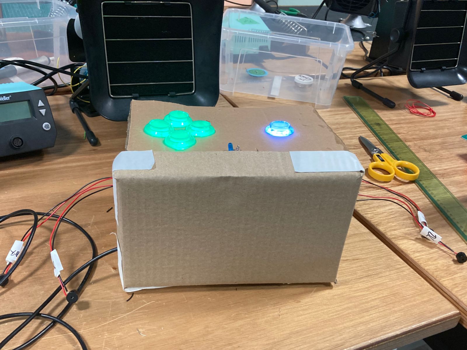
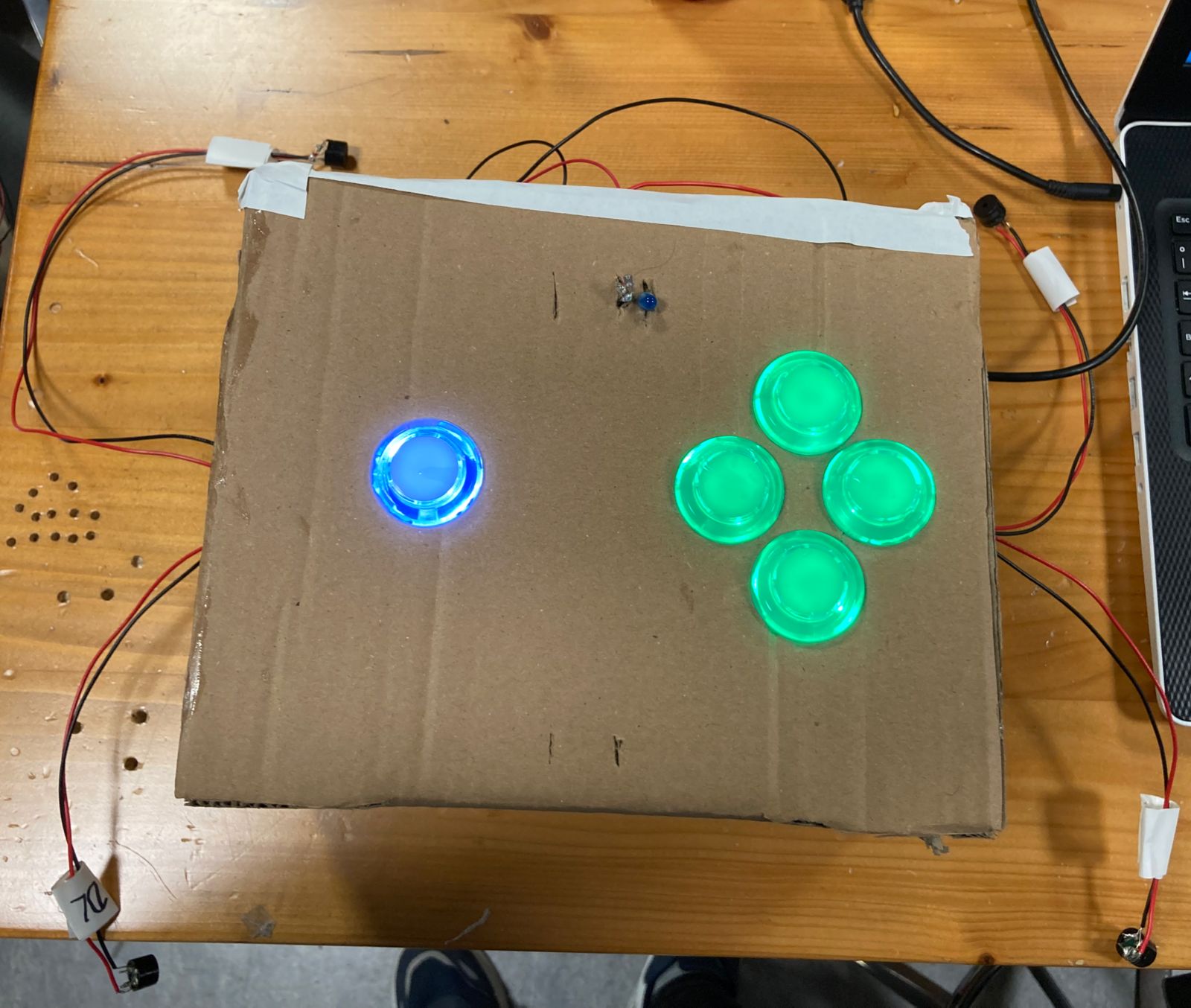
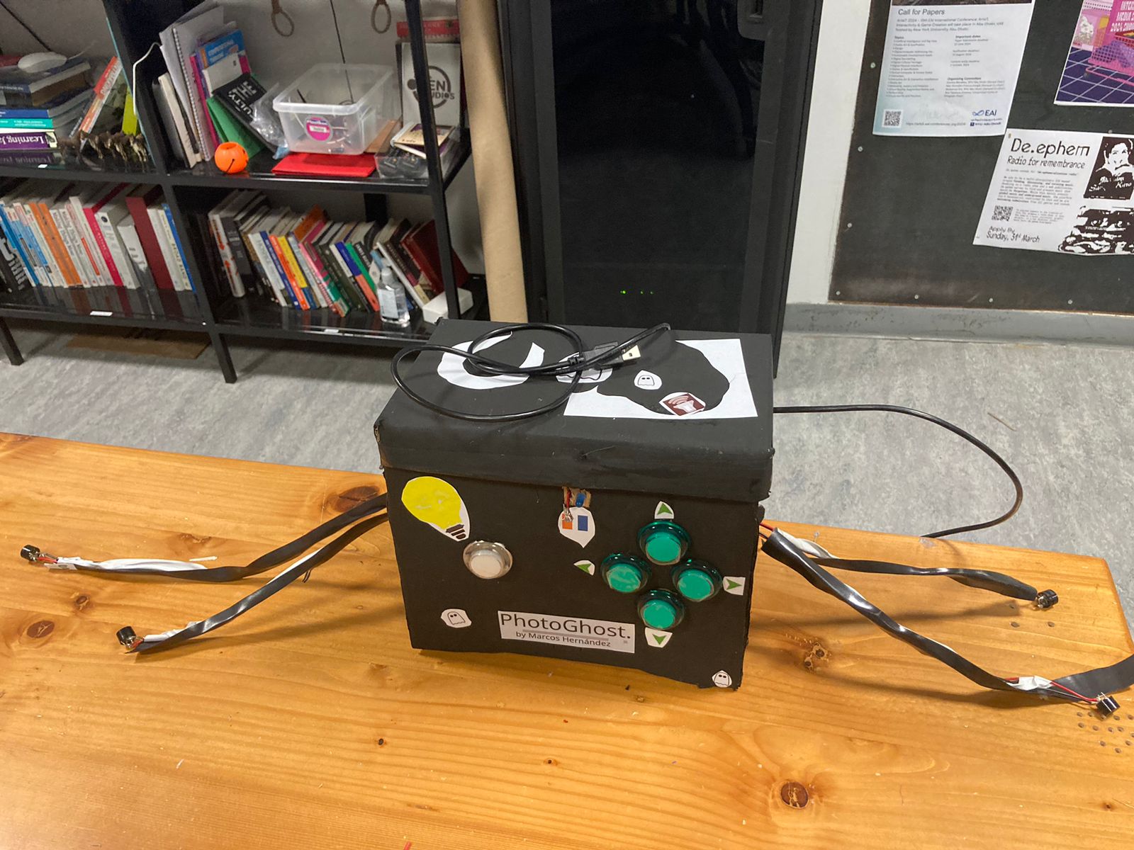
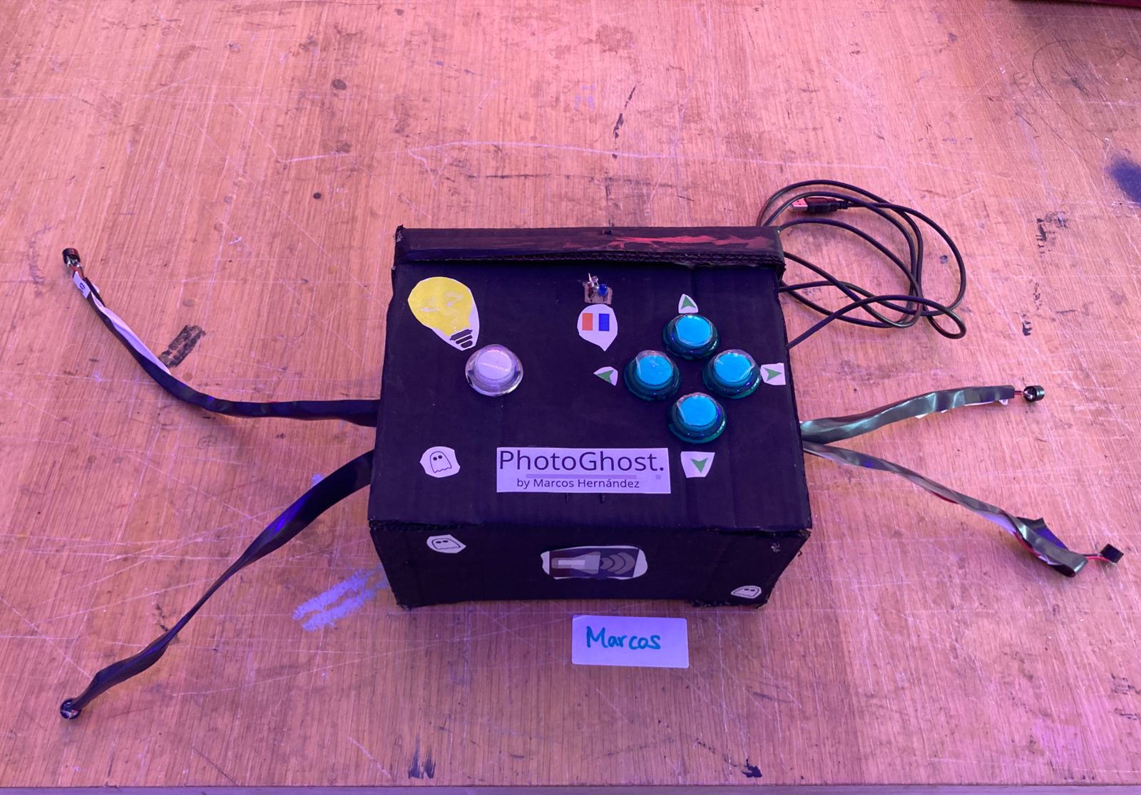
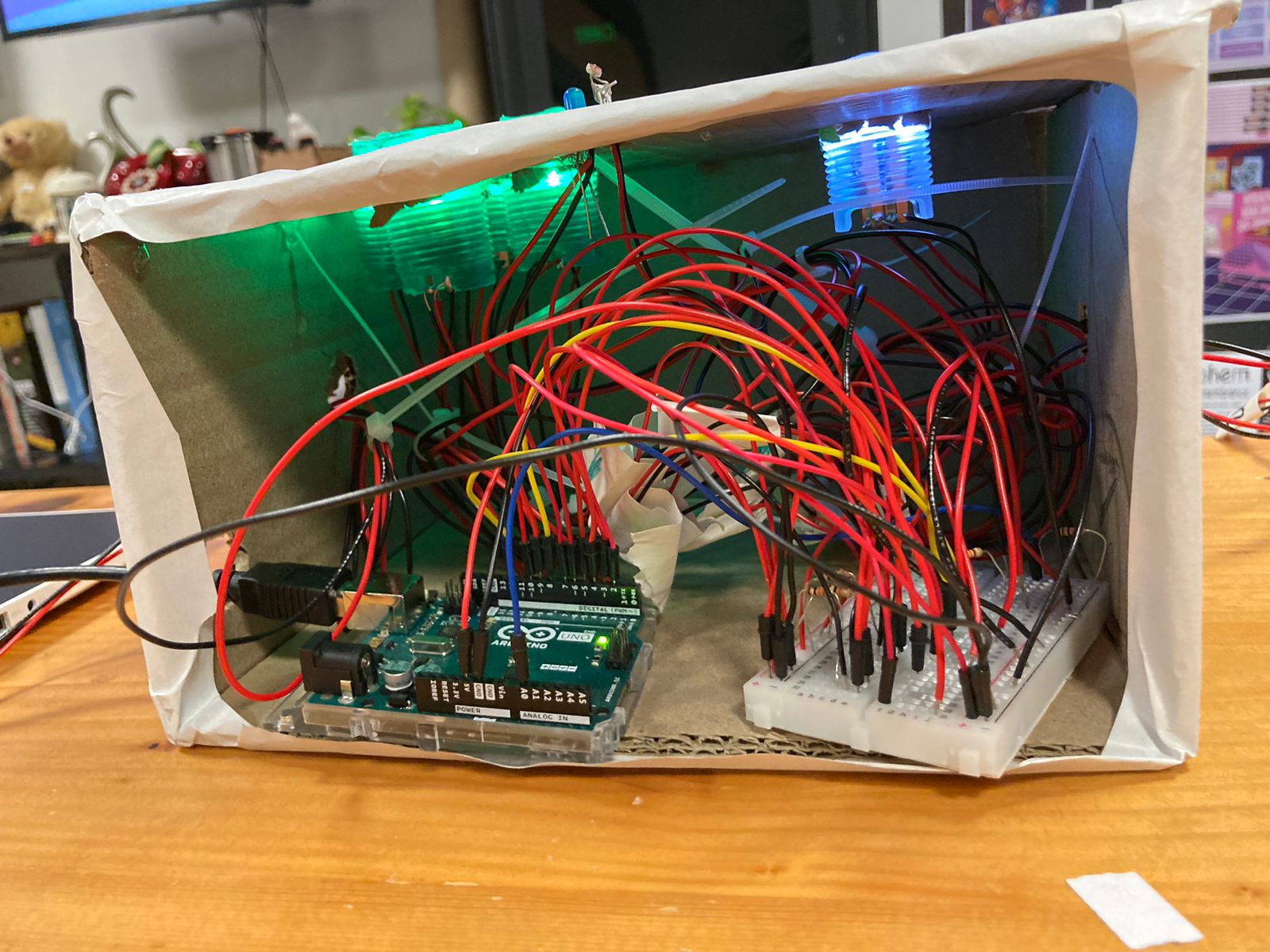
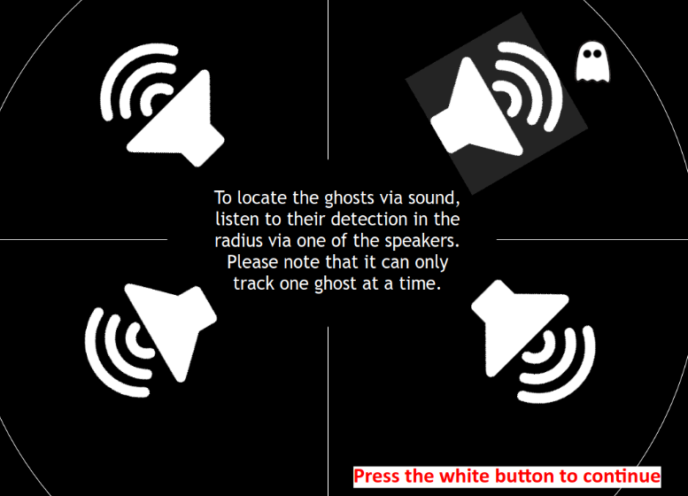
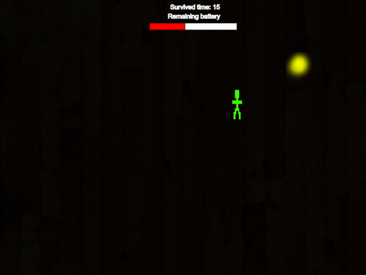
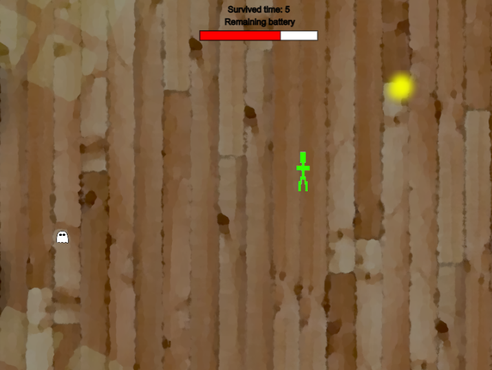
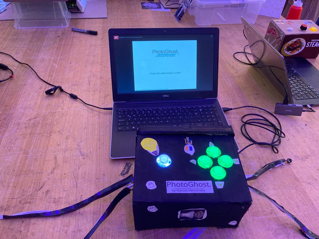
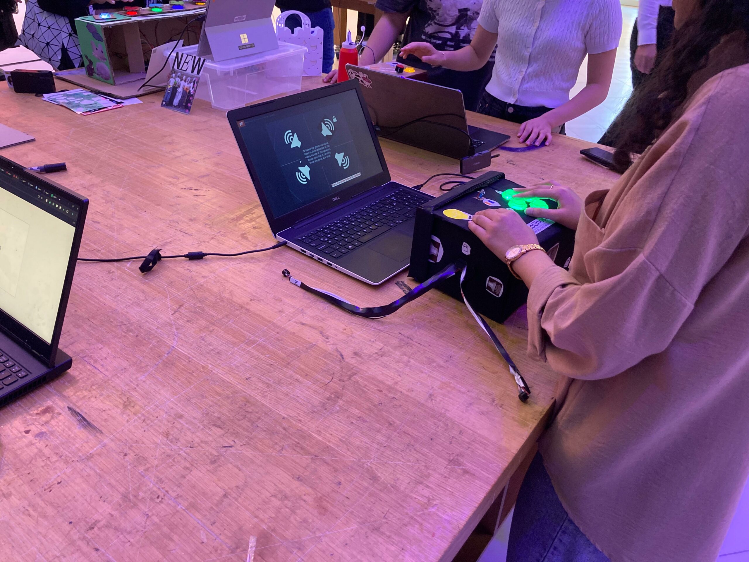
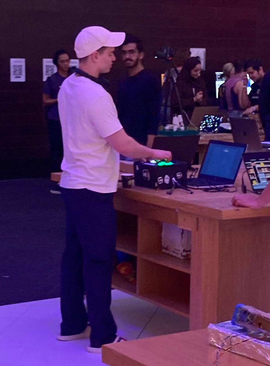
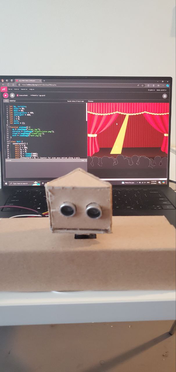
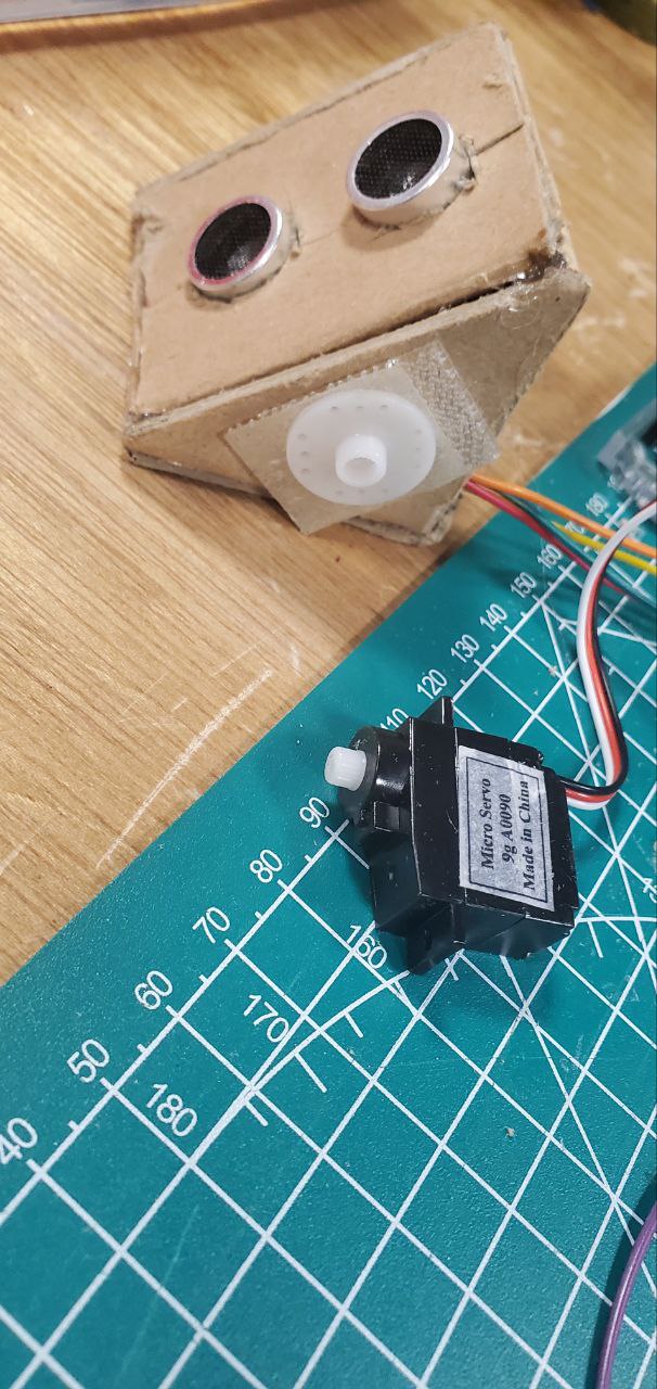
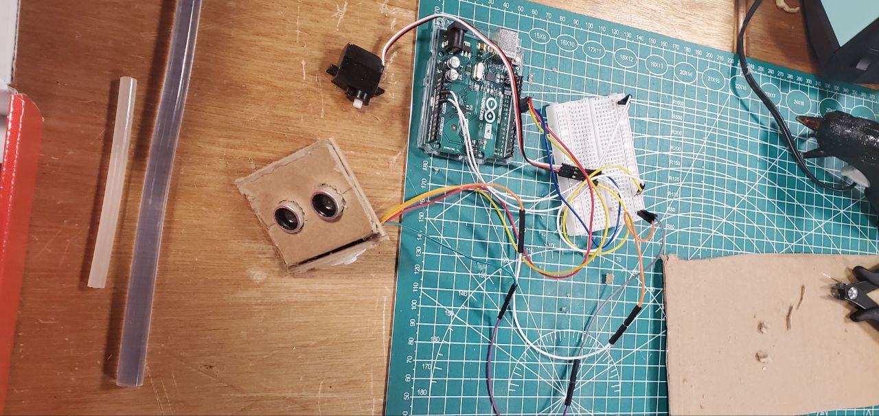
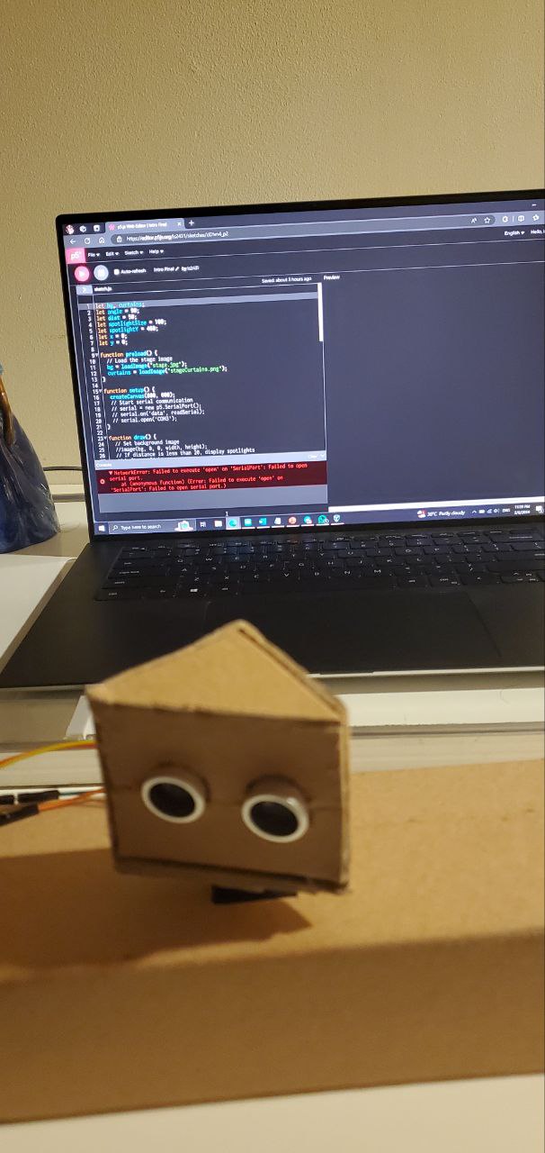
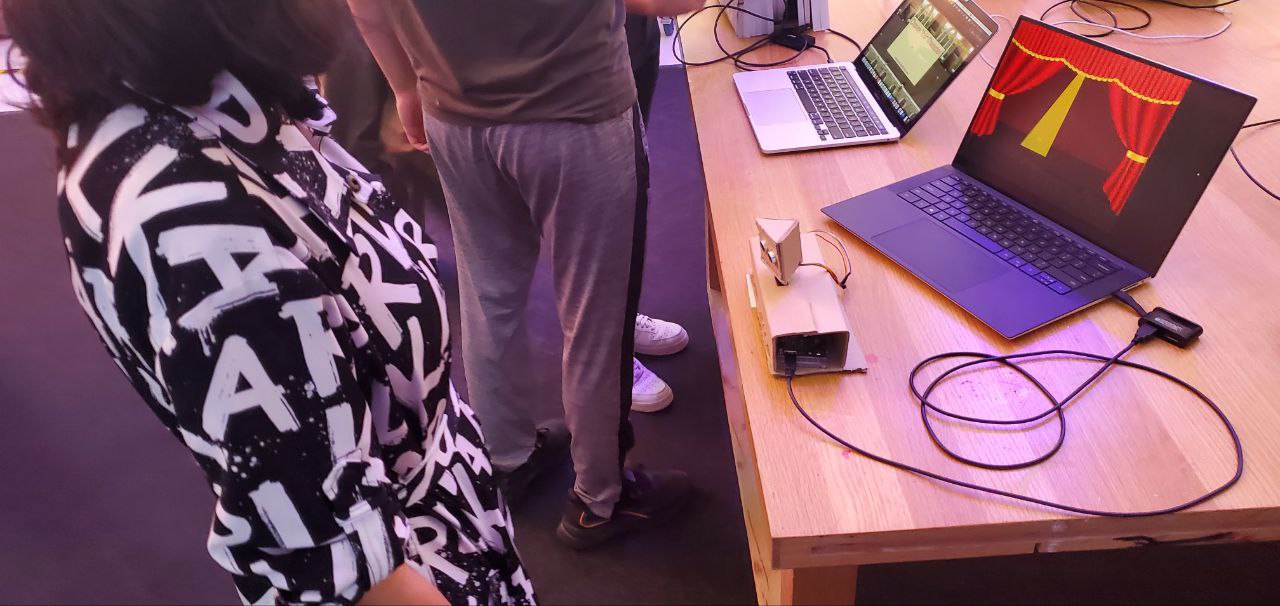
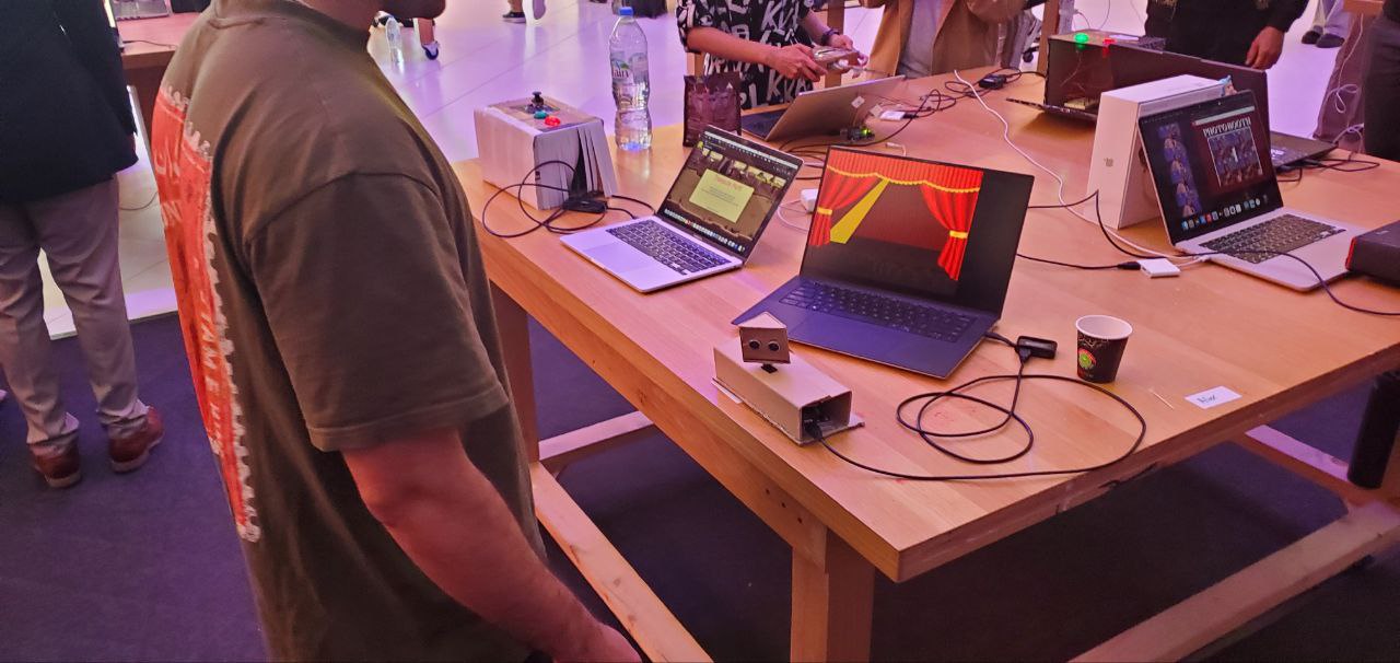
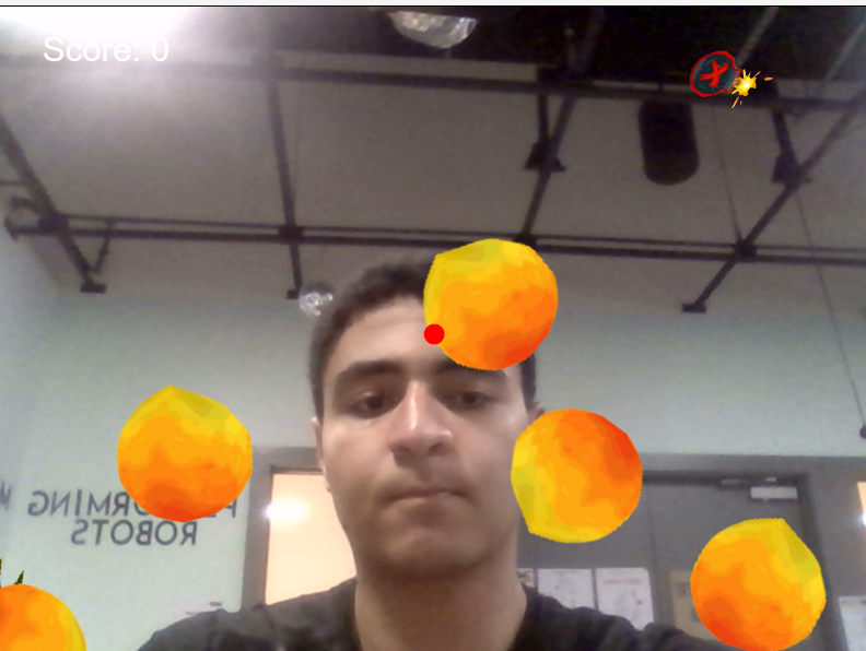
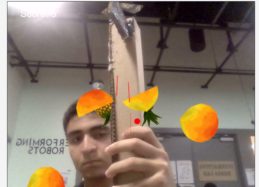
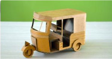
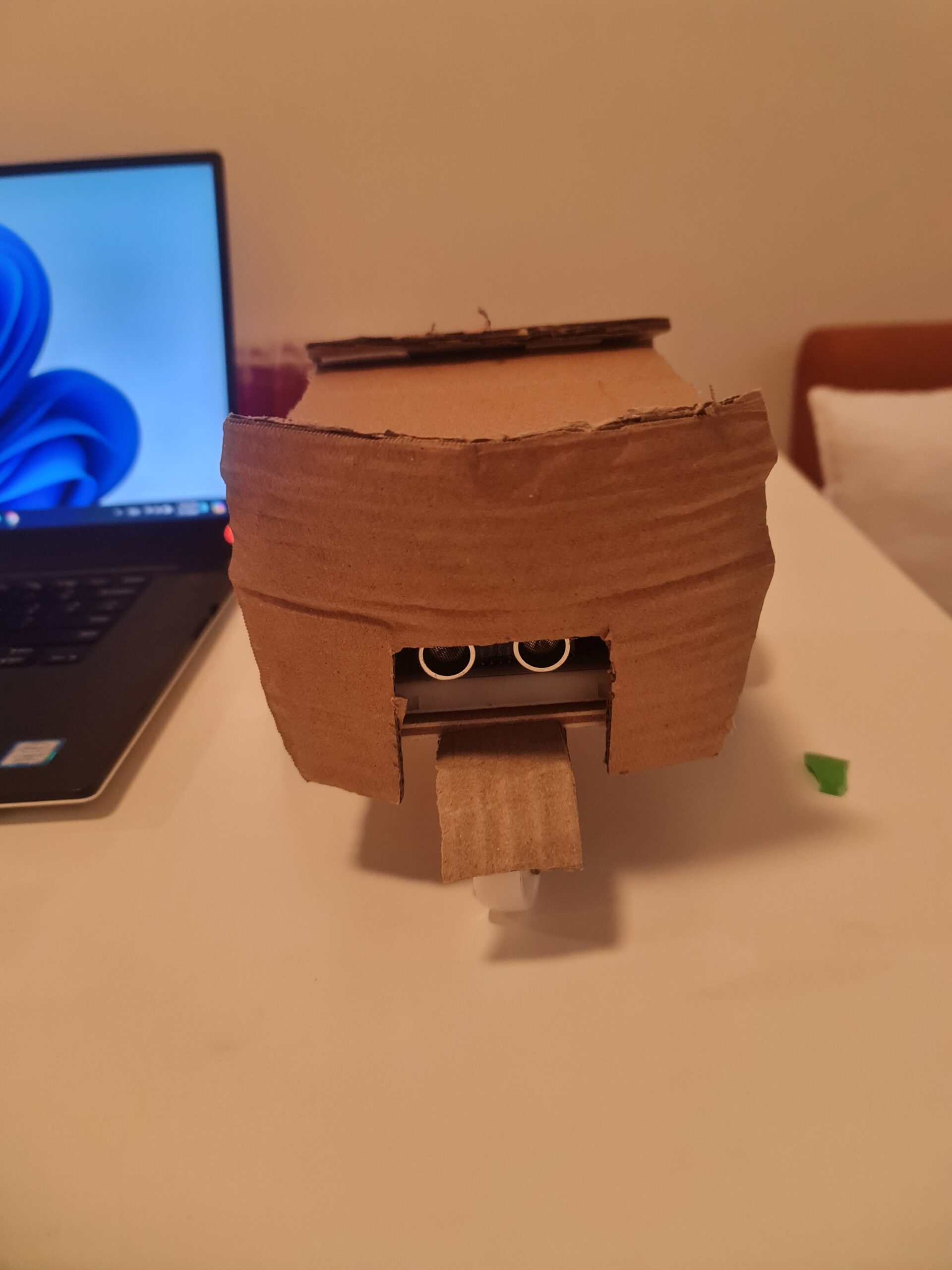

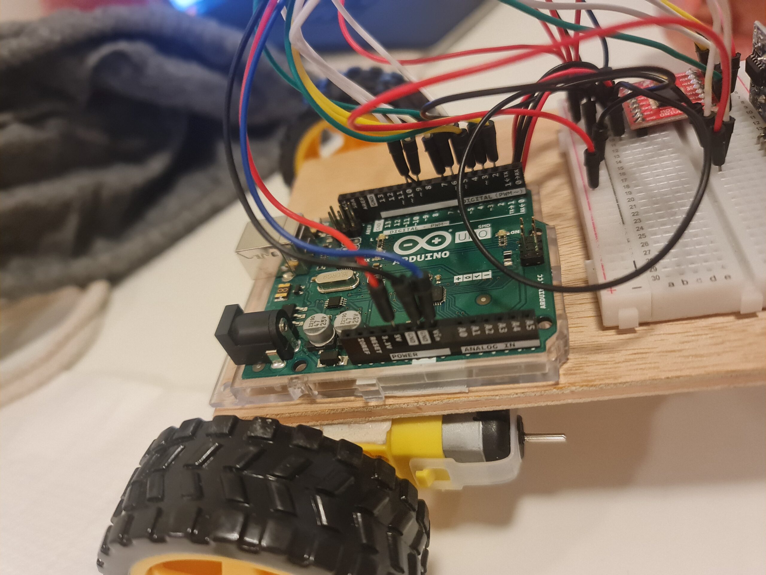
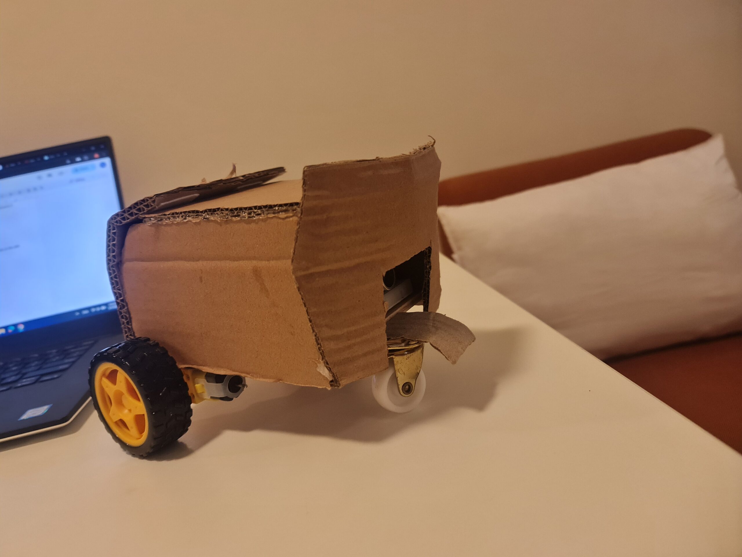
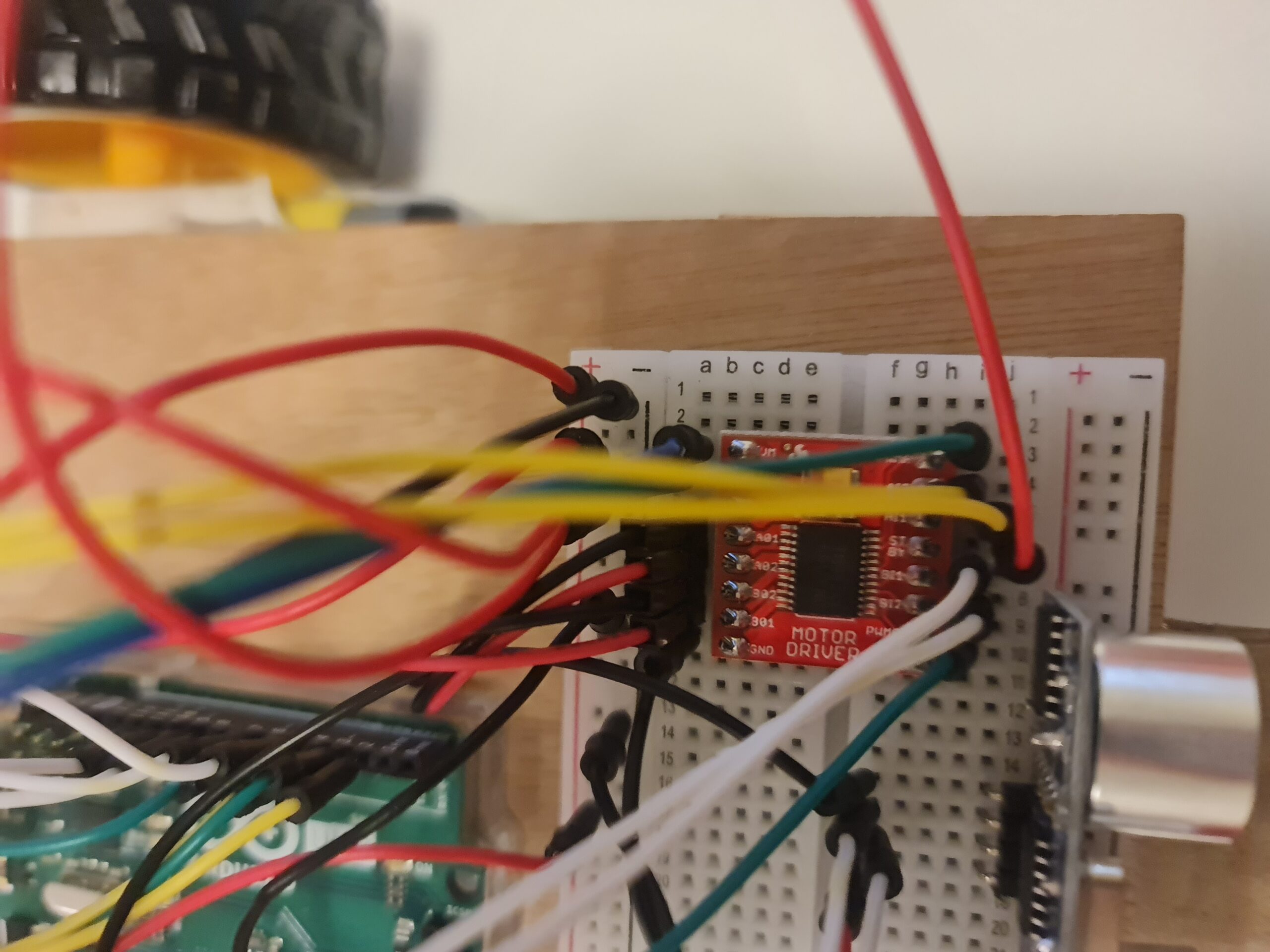
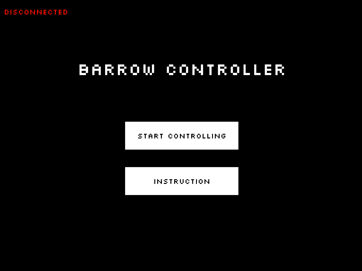
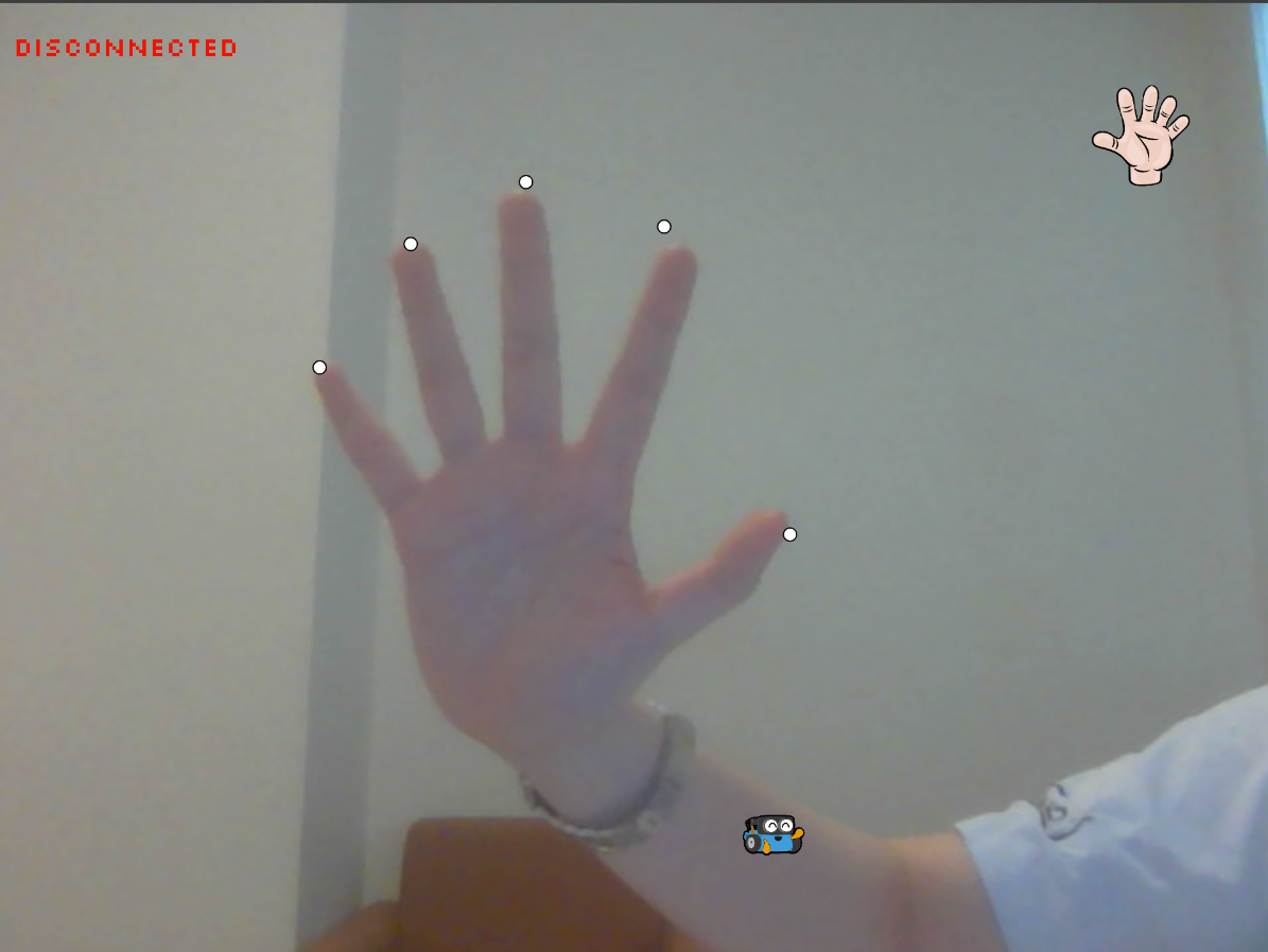
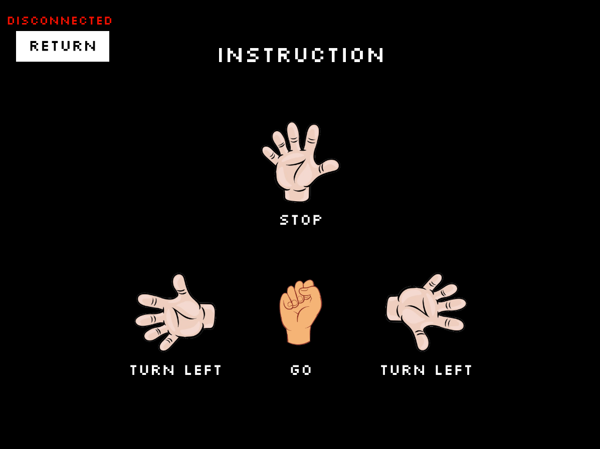
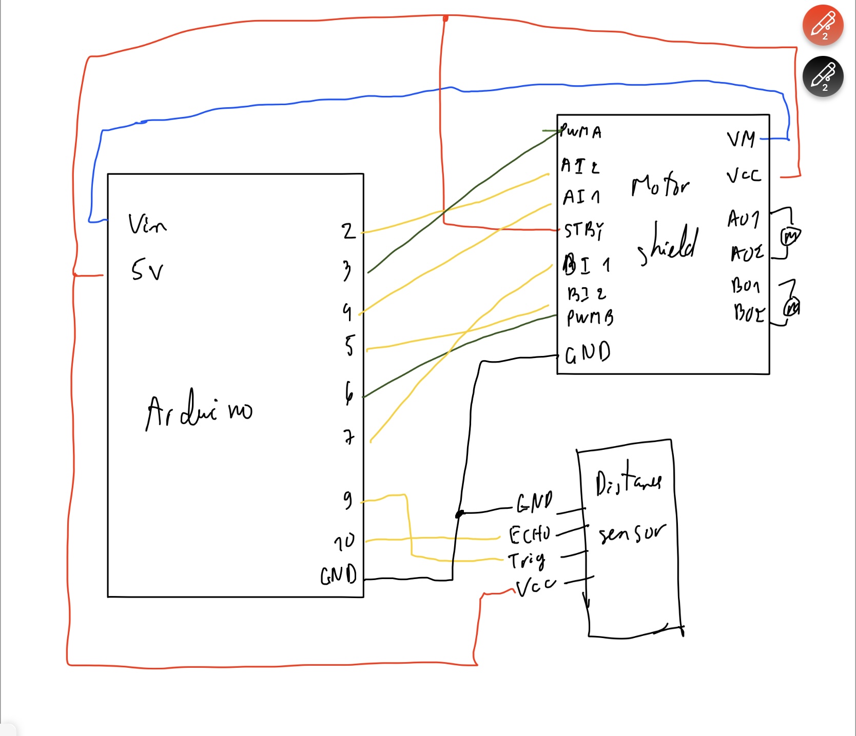
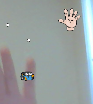
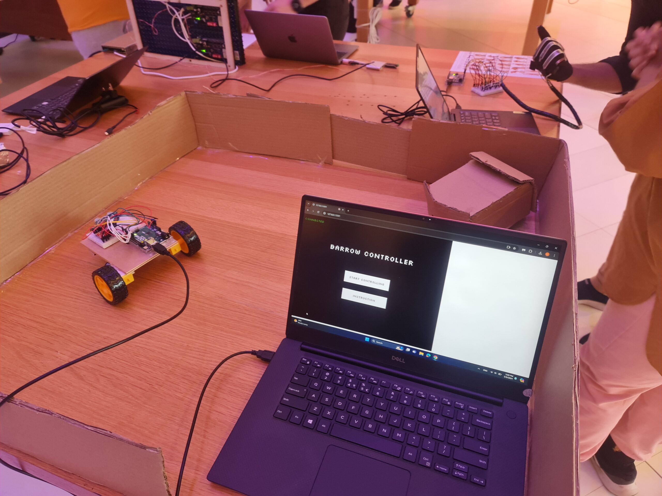
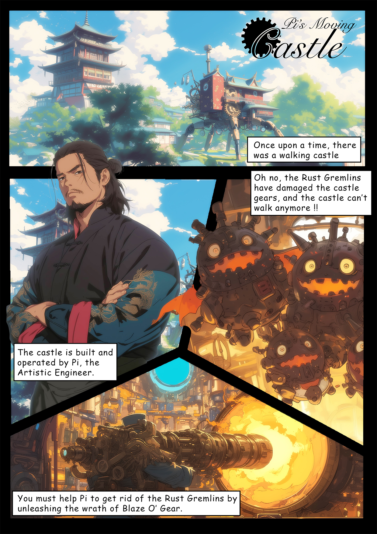
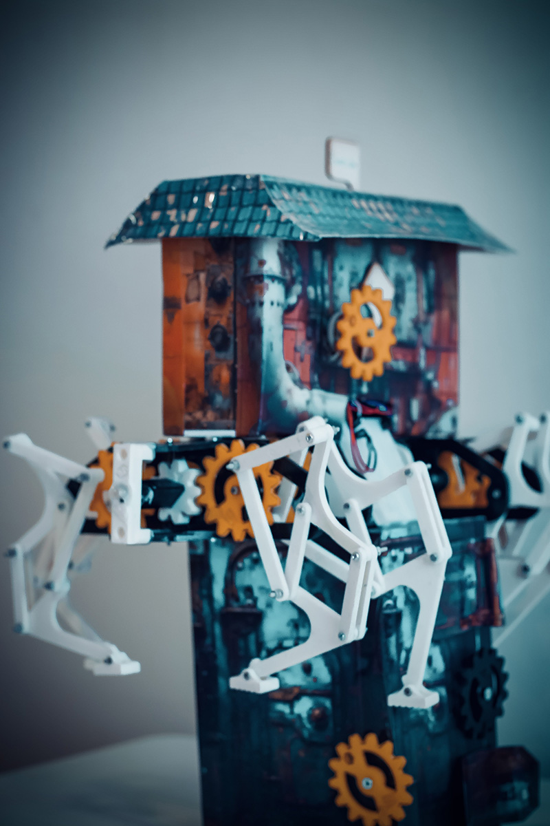
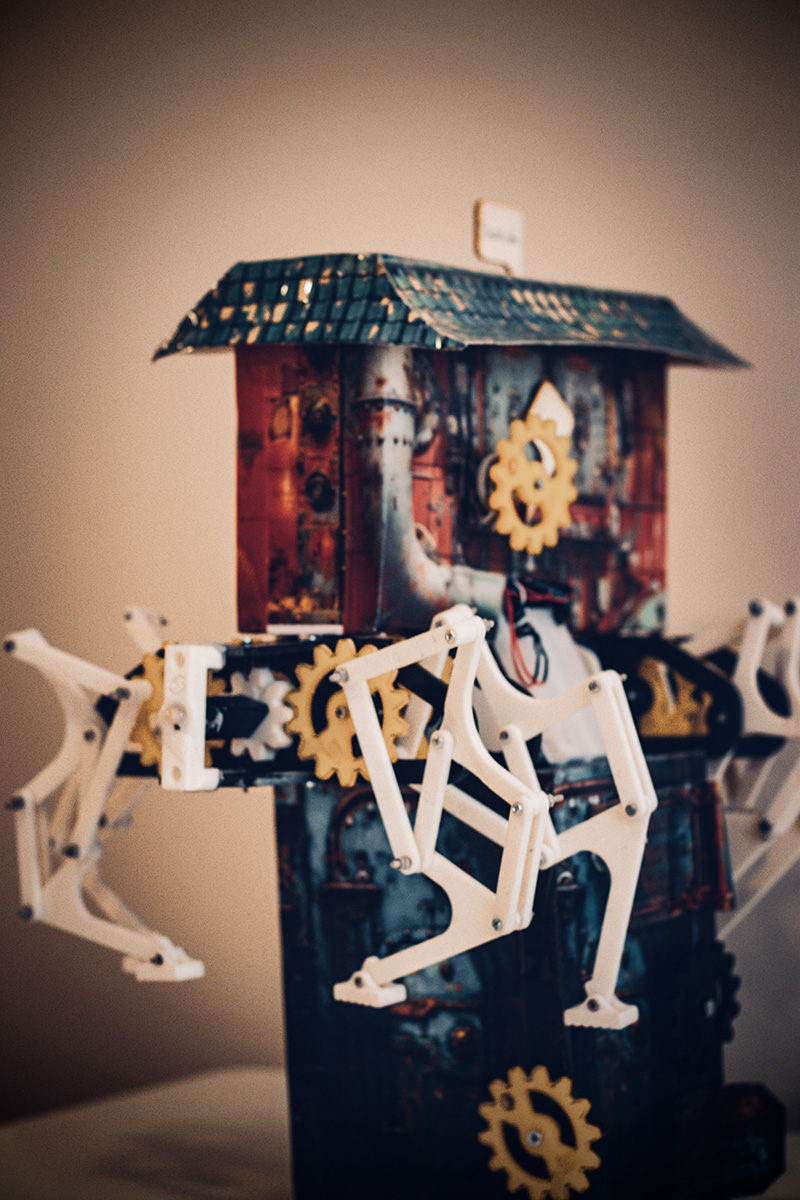
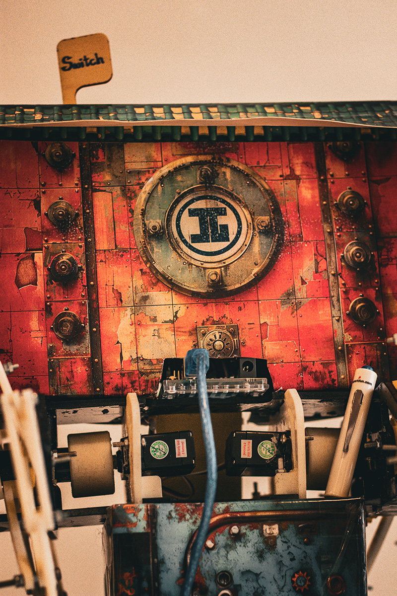
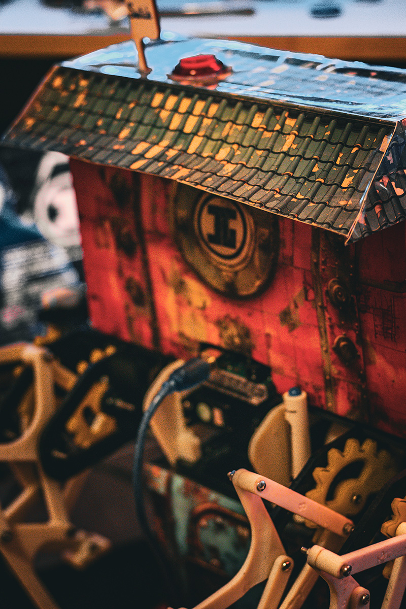

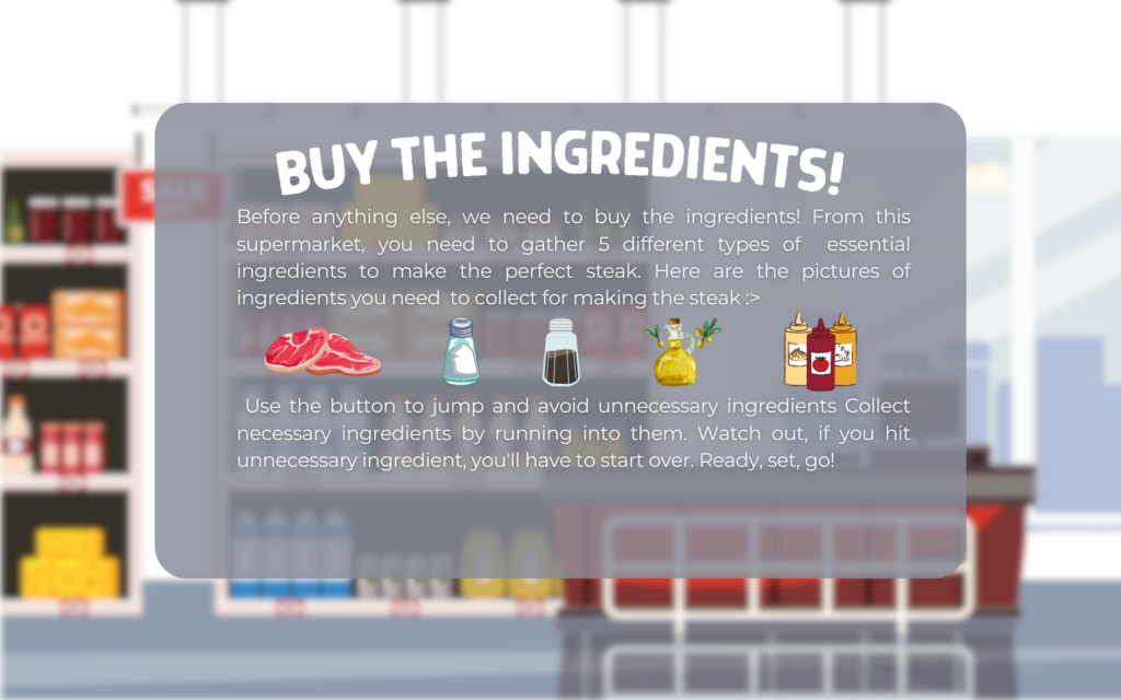 Stage 1 instructions
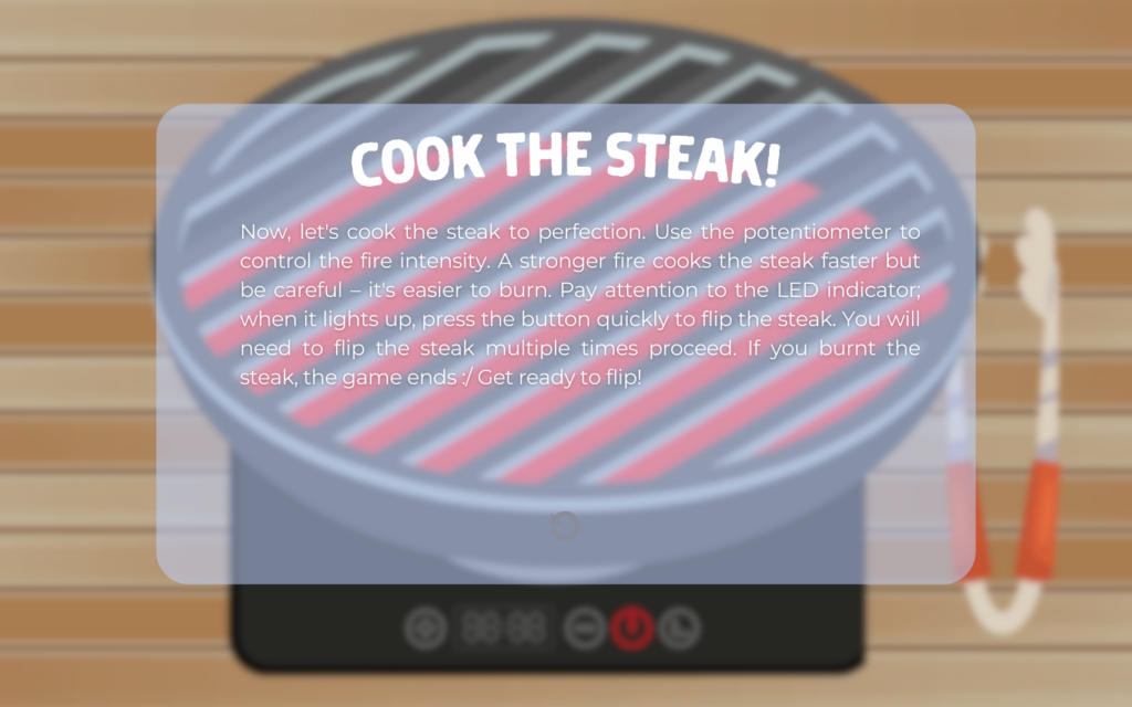
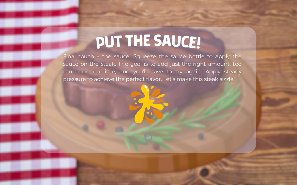
 game ending page
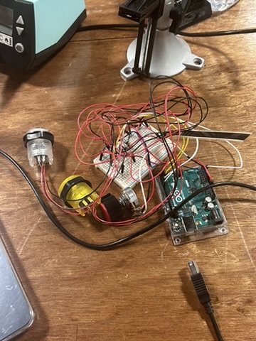
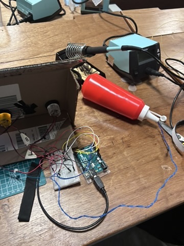
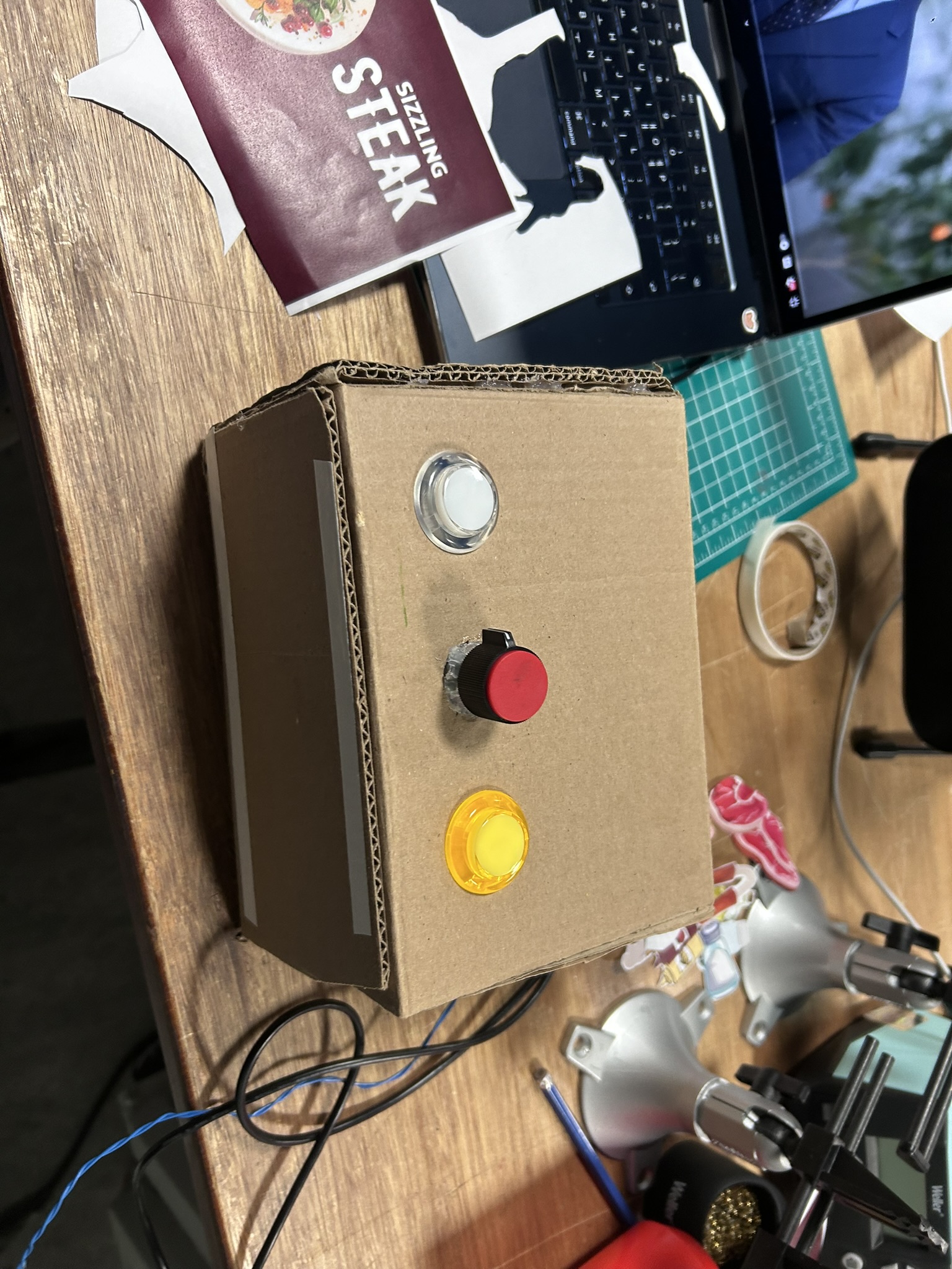
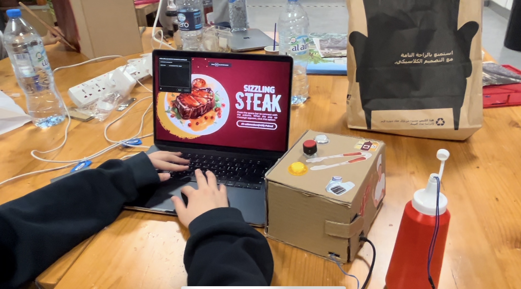
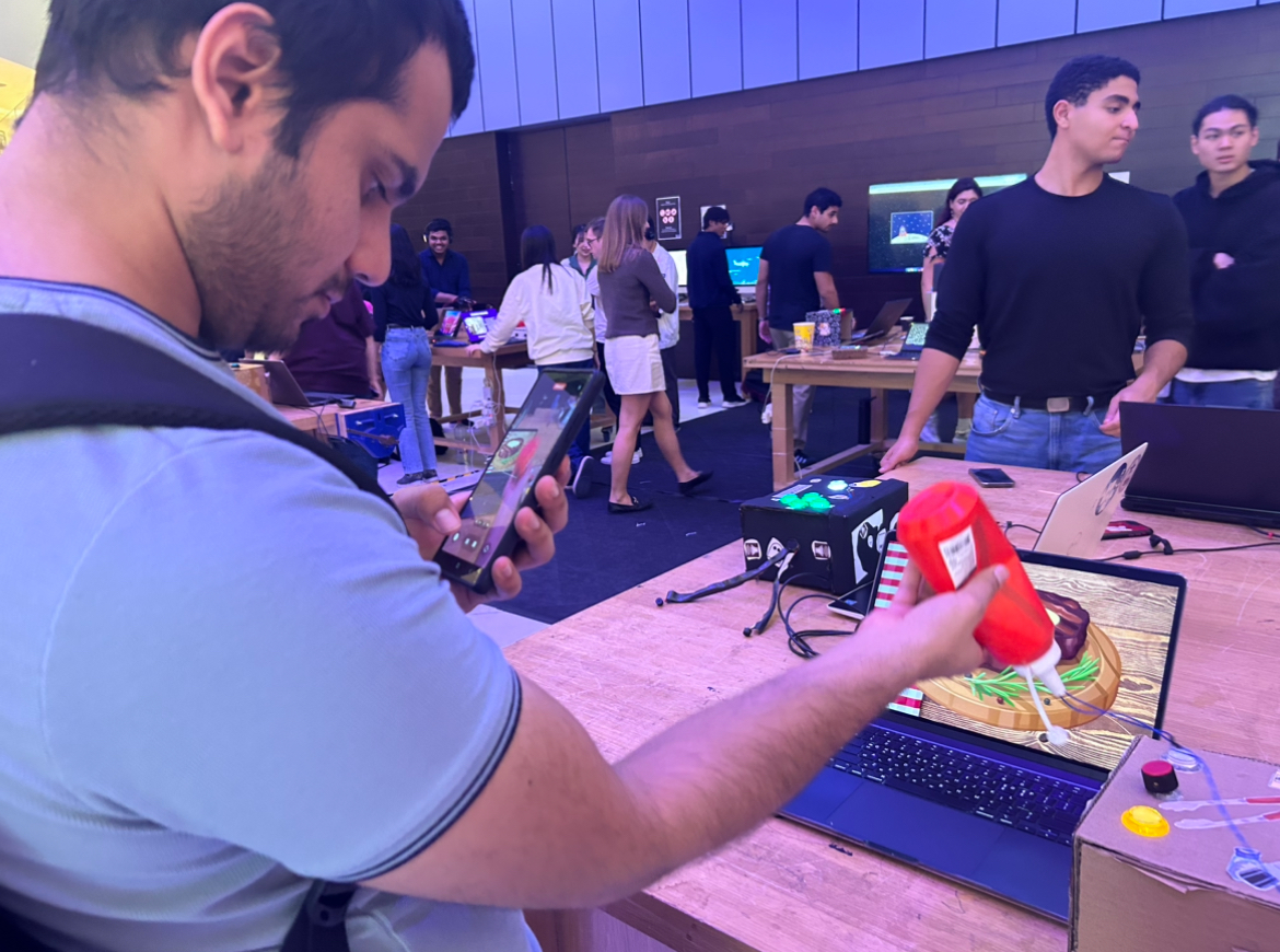
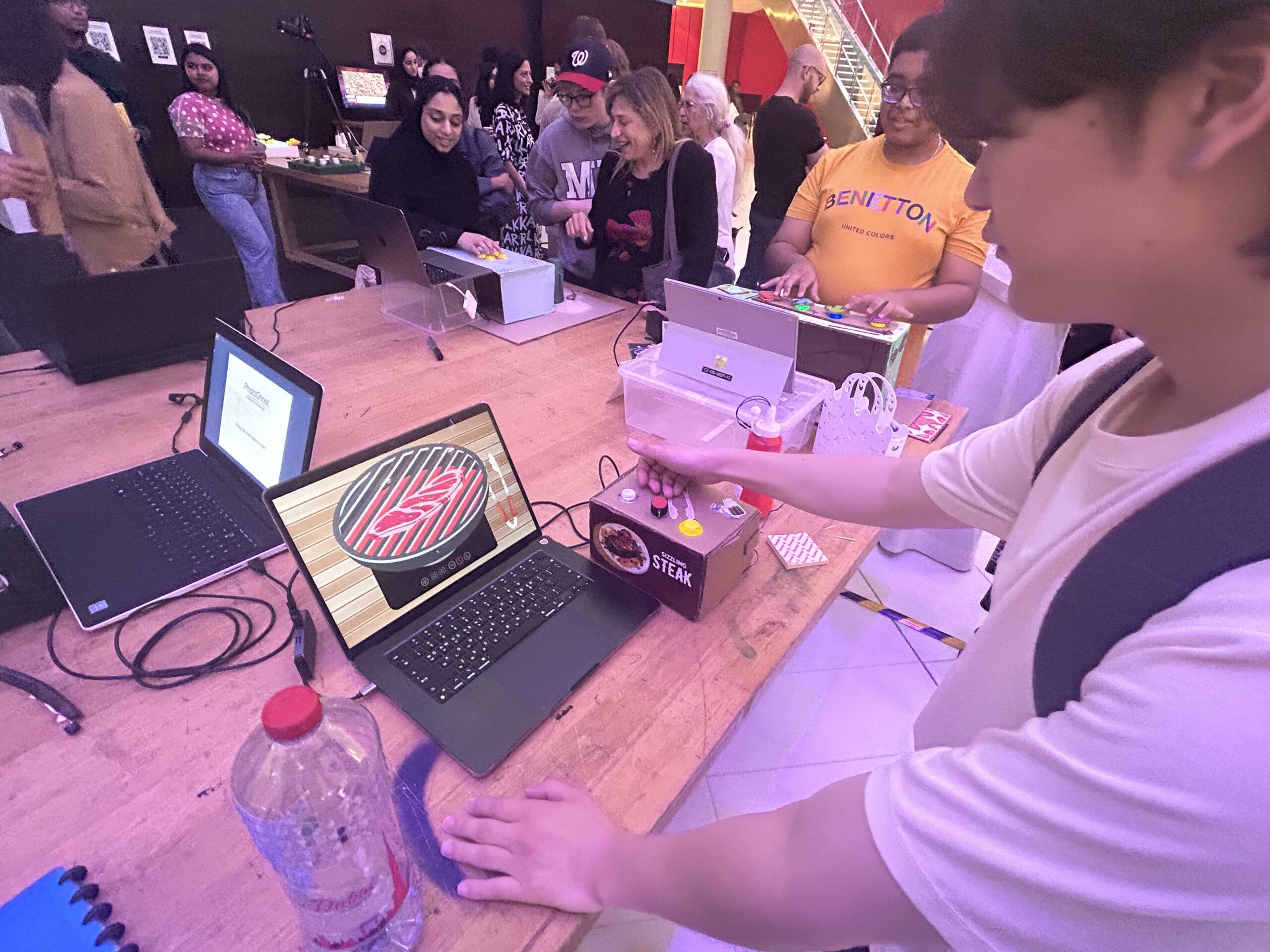
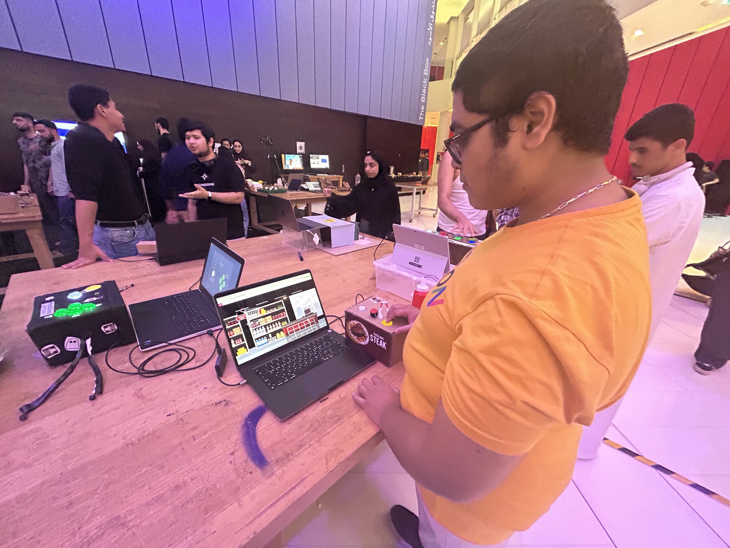
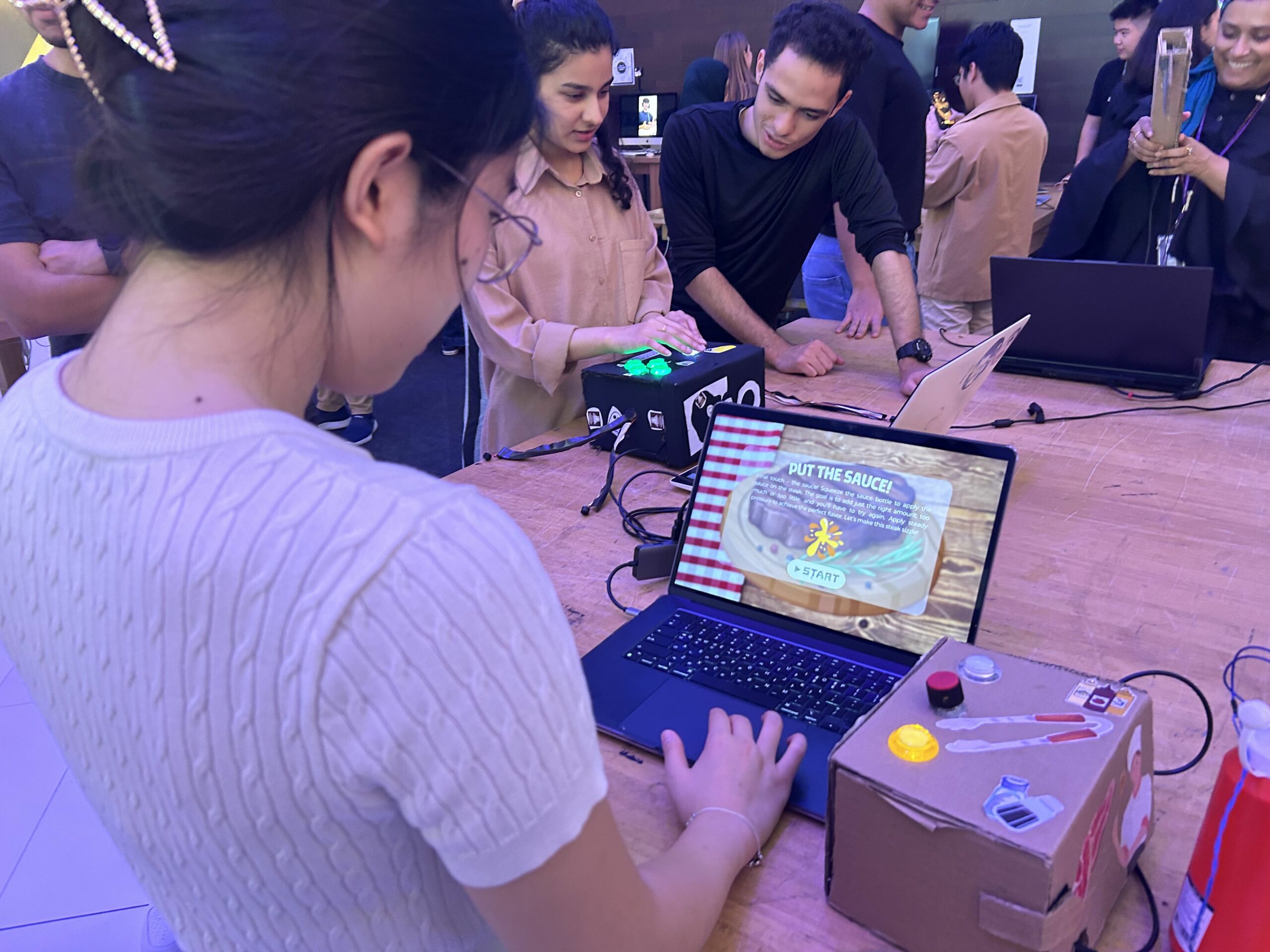
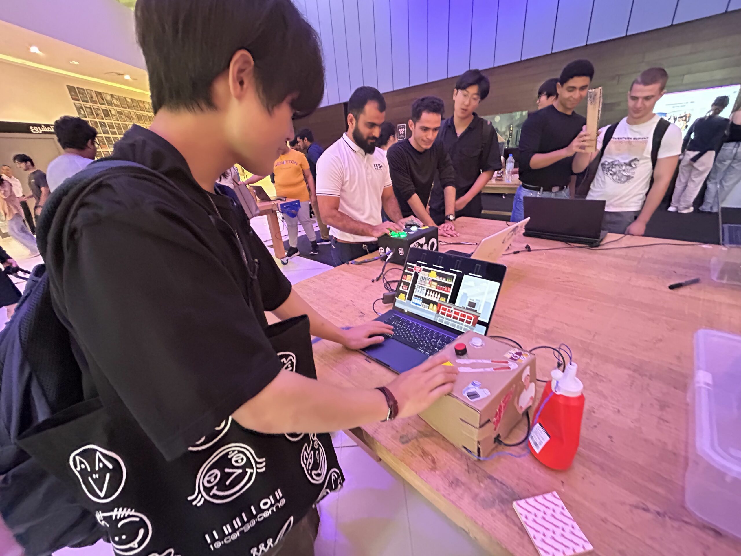
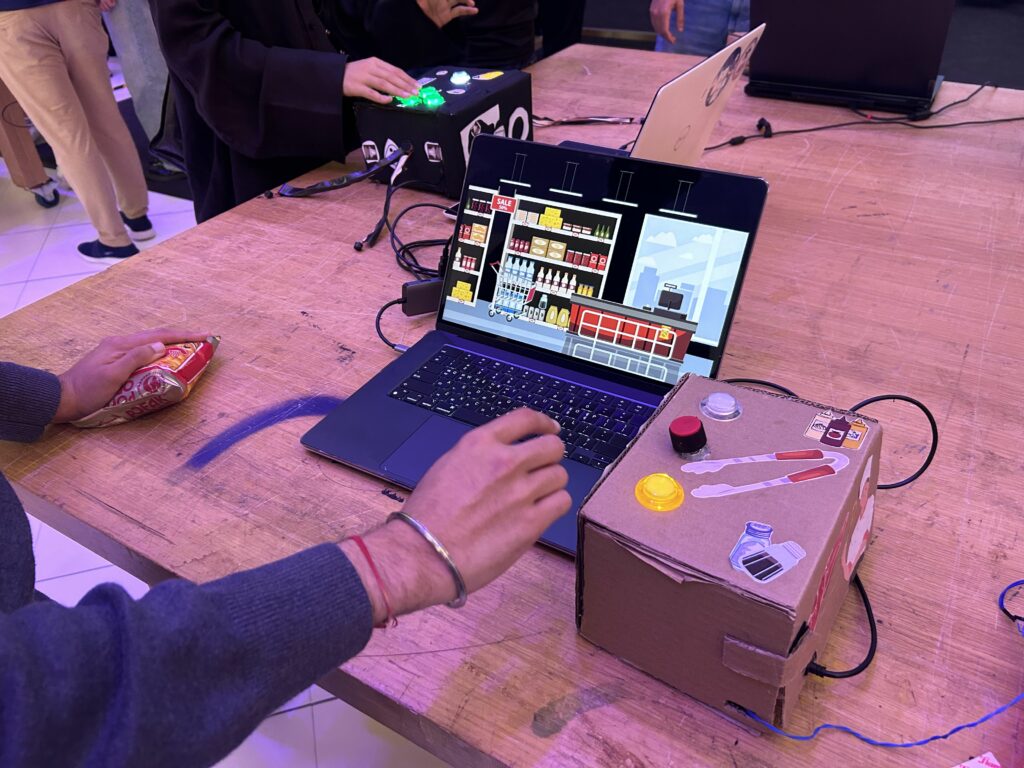
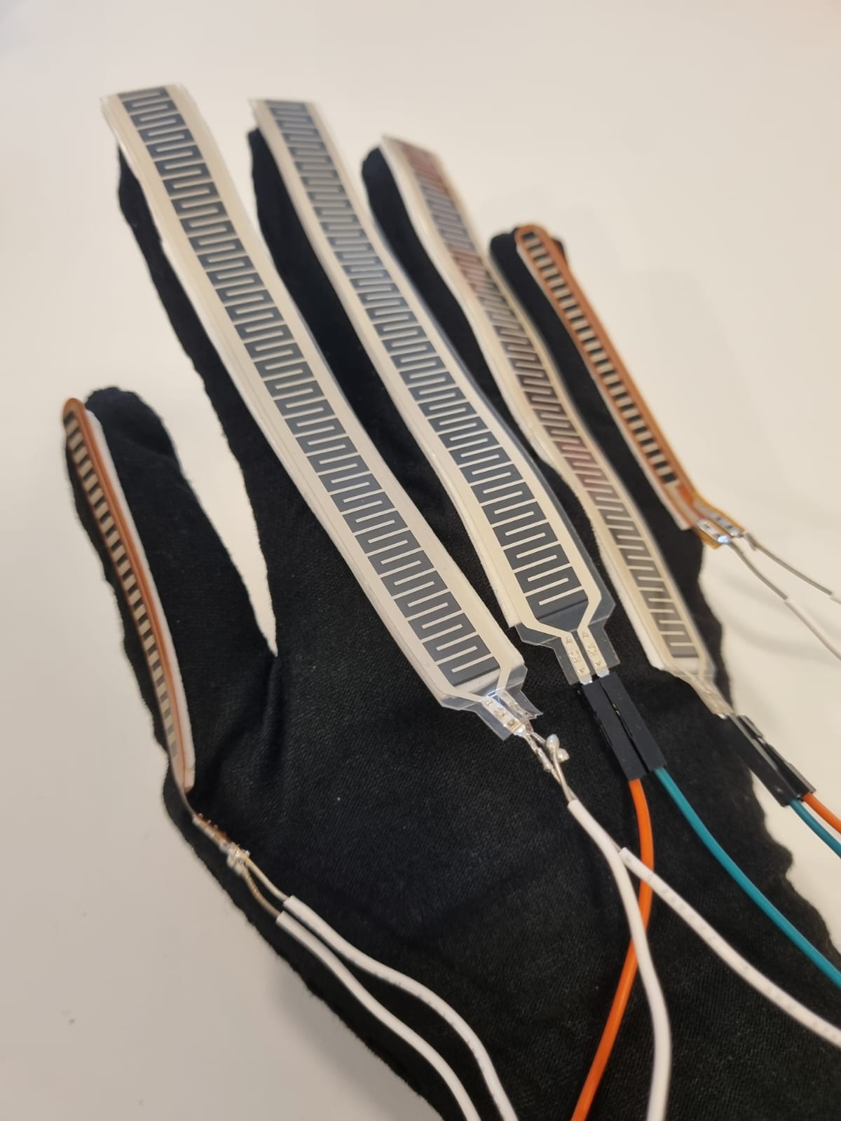
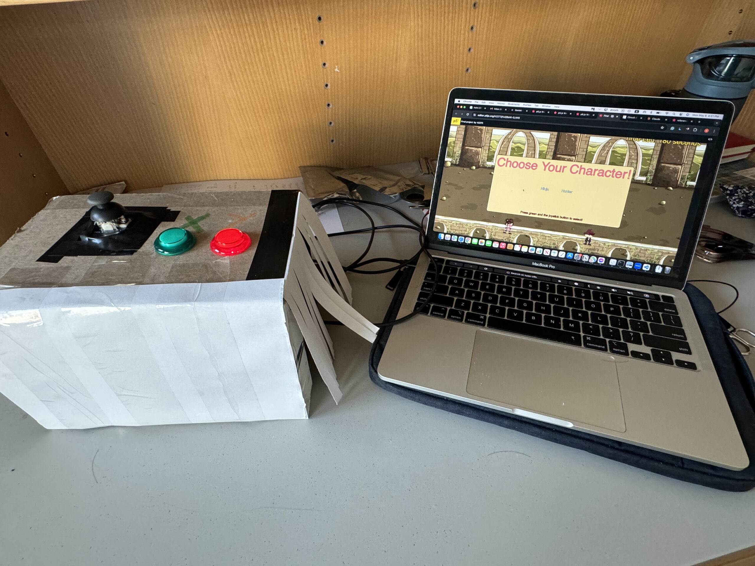
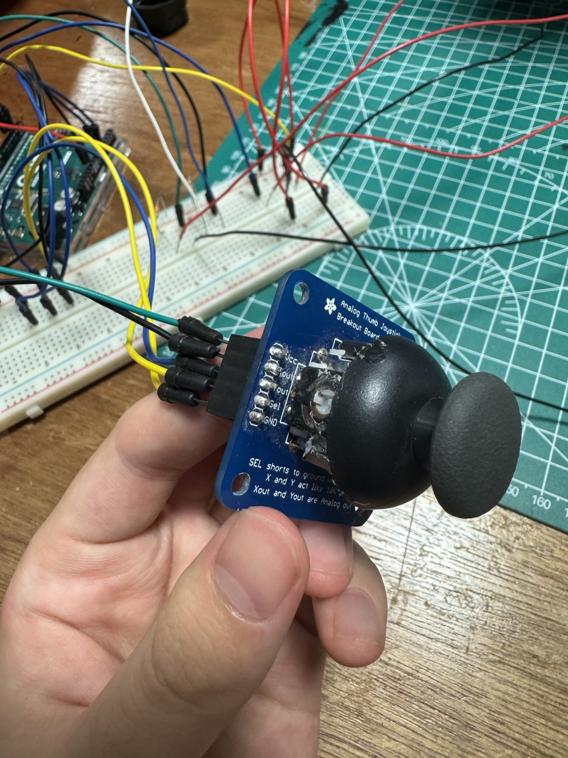
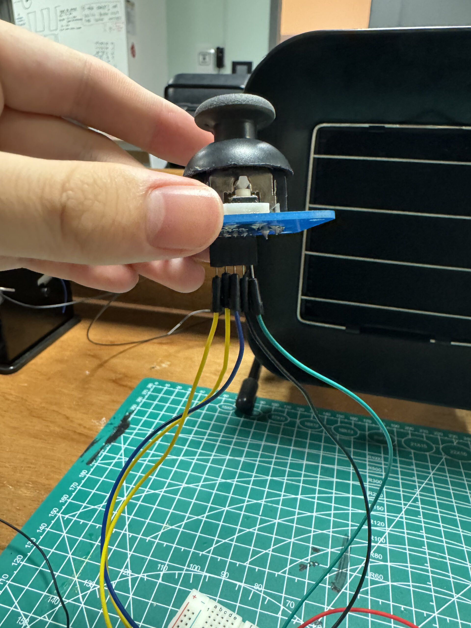
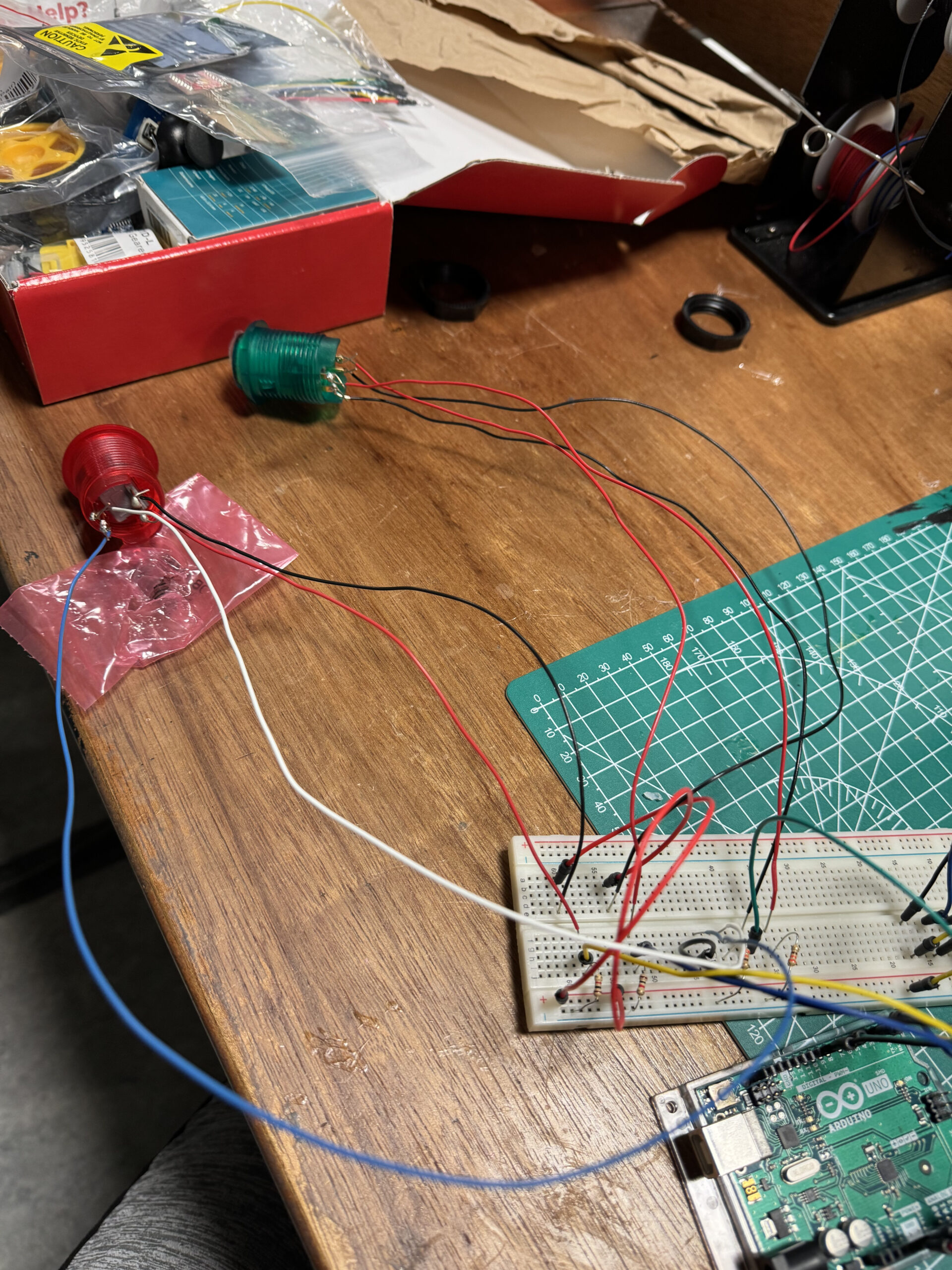
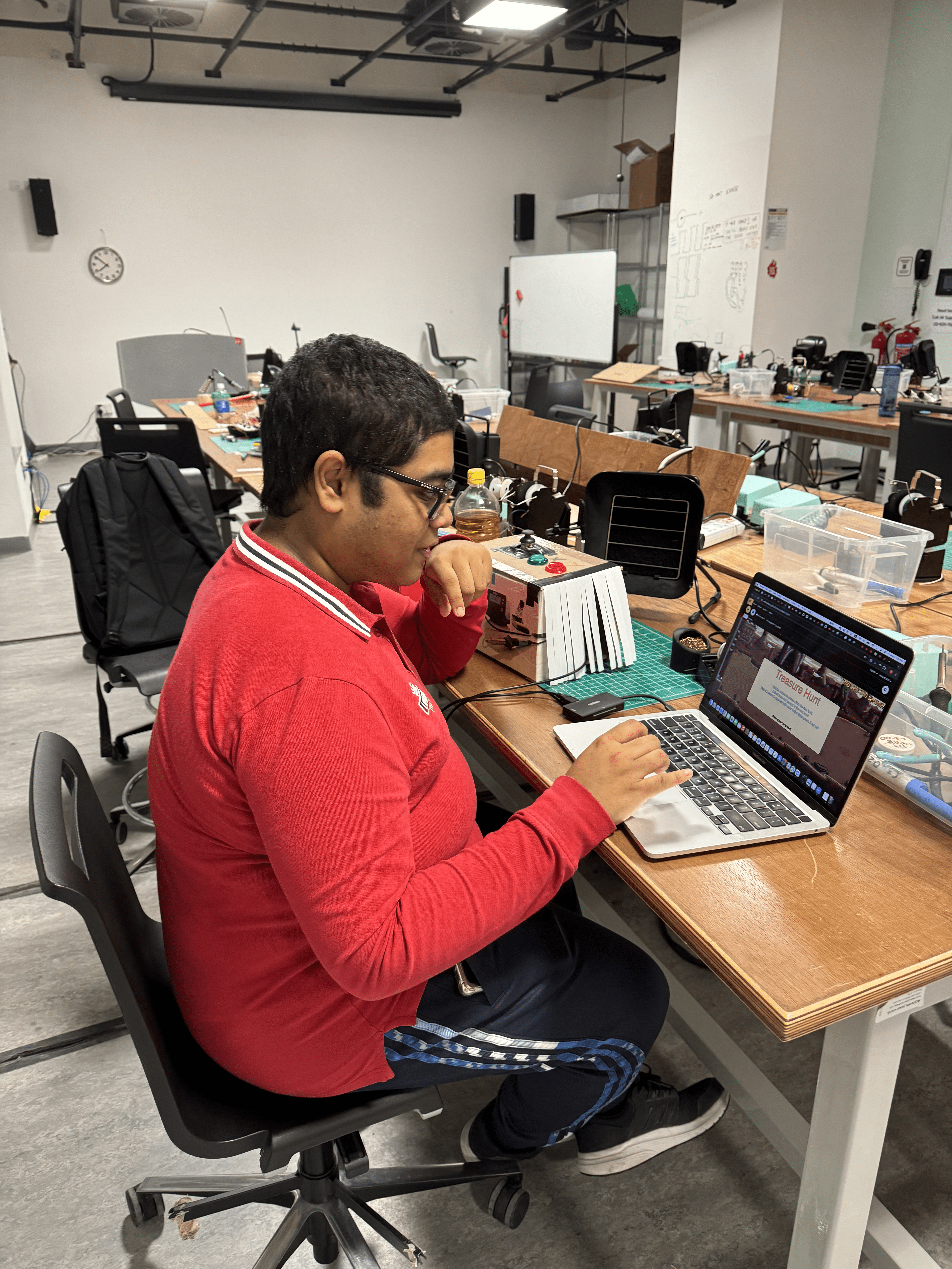
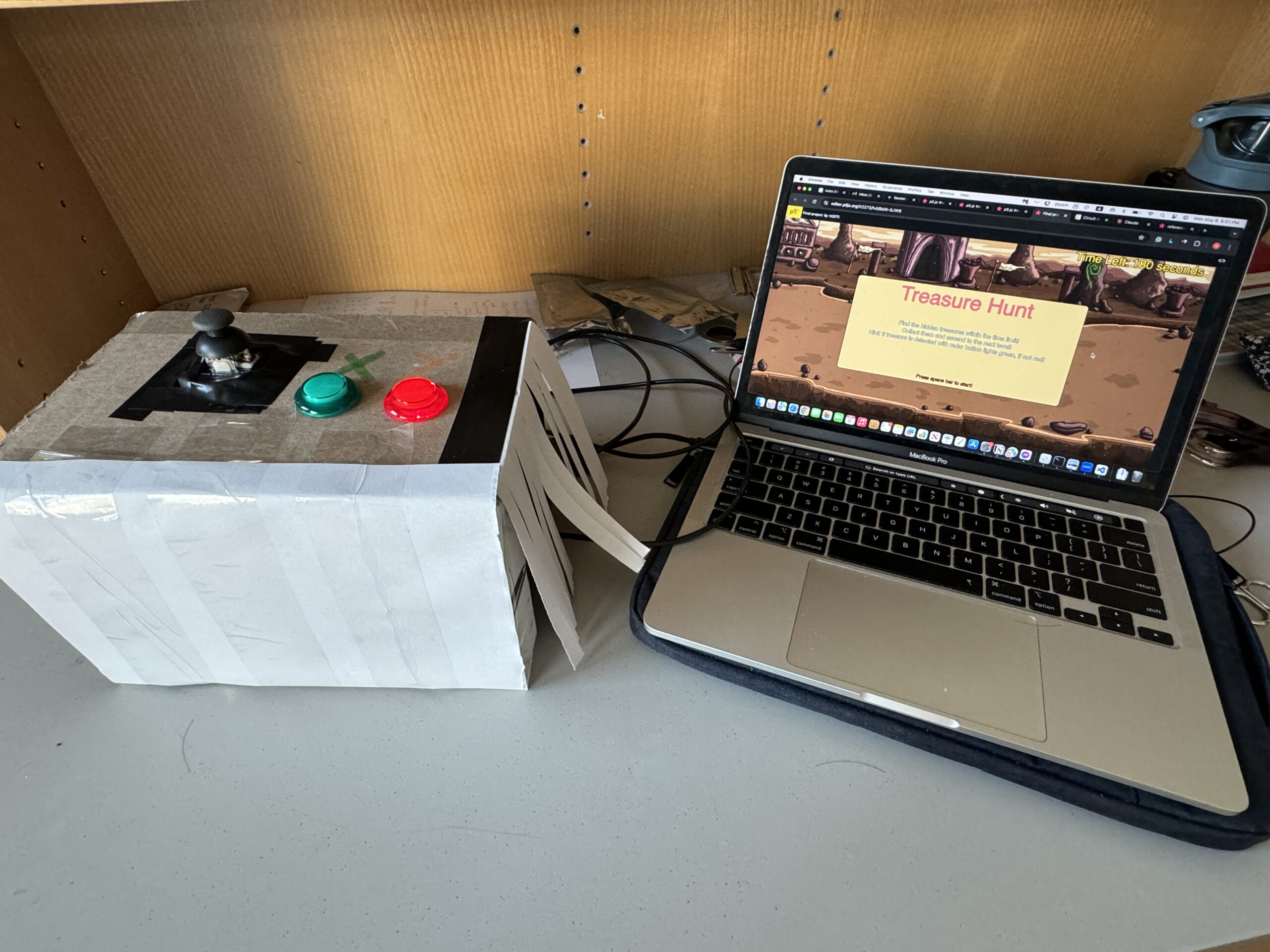