Concept
Inspired by “GarageBand”, an application on Apple devices, I wanted to create an interface that allows the users to play musical instruments wherever they are at. As the title of the program suggests (“Corner of the Room Band”), the goal of this interaction was to provide access to instruments whether the users are in their room or anywhere else. When I was younger, I used to play with GarageBand. While it provided access to instruments such as piano and drum, I always hoped a different instrument to be added. However, my hope was not met through GarageBand and hence my project was made to satisfy my desire.
User Test
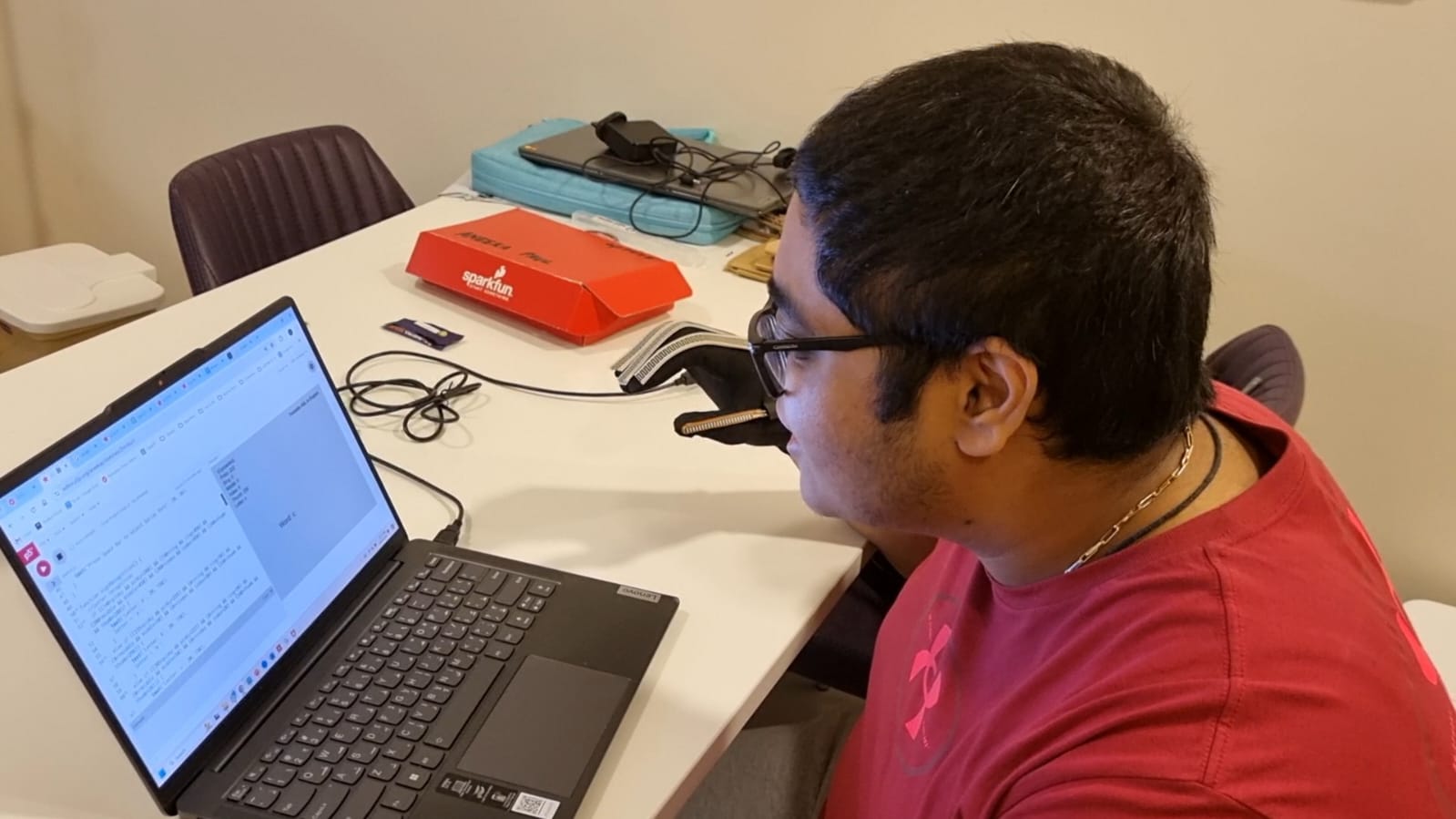
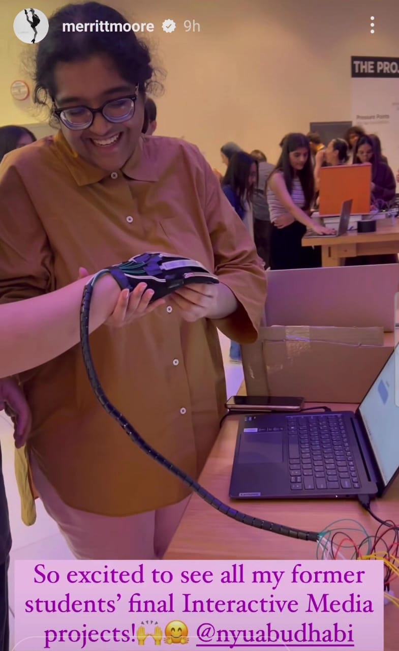
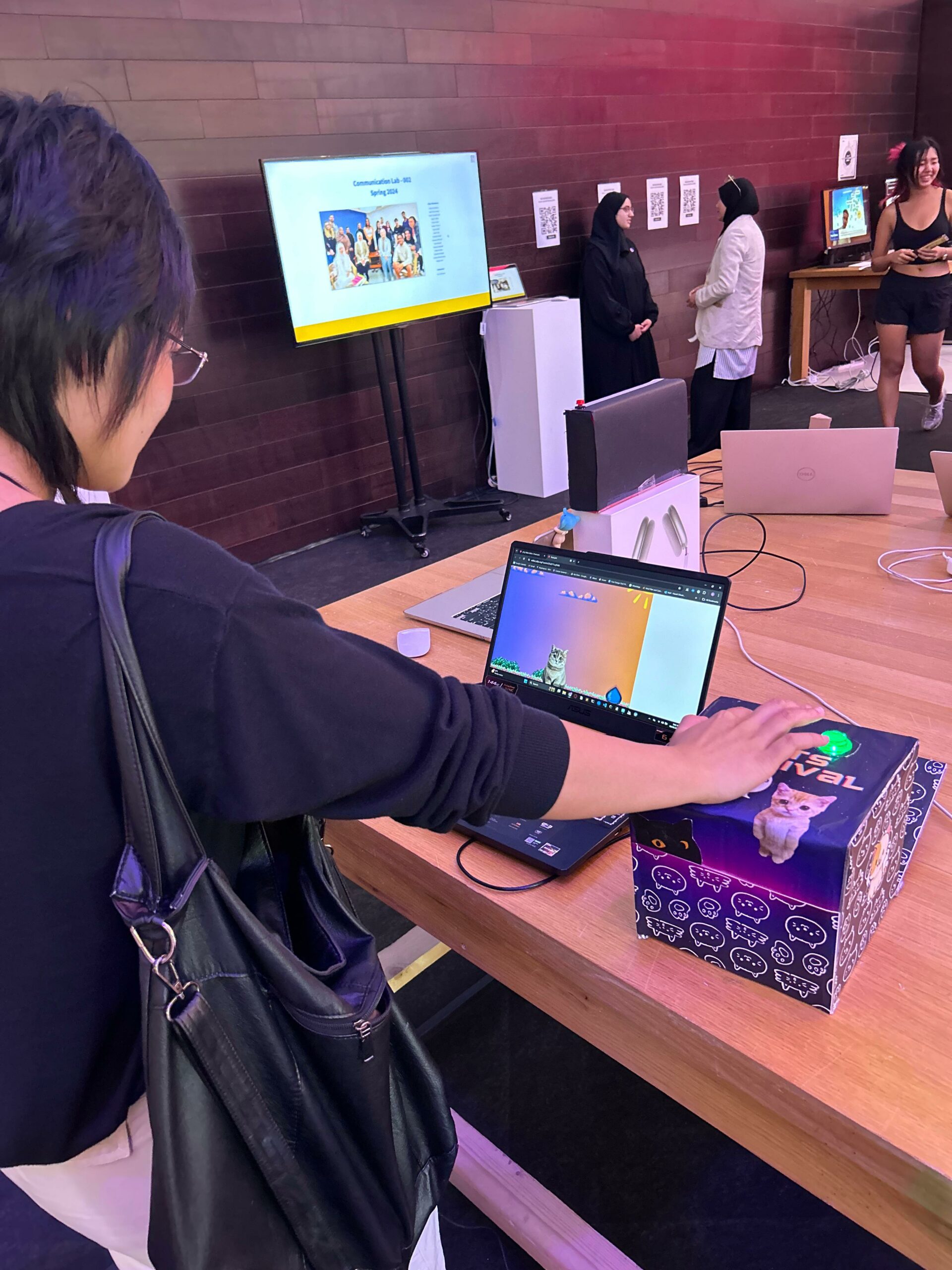
After I have built and created the project, I asked my friend to use the program. The video and image below illustrates my friend using the program:
User Testing
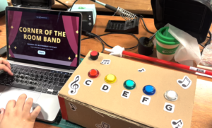
After the user testing, I made no big changes to p5 or Arduino because everything was pretty much set. My friend successfully navigated and used the program without difficulties.
Implementation
The overall interaction looks like this: p5 changes pages or the “gameState”, buttons on Arduino sends signal to p5 when pressed, sound files that correspond to each button is played through the laptop.
More precisely, the user navigates through different pages by clicking on the screen made through p5. When the user enters either the piano or flute page, sound files that are tied to each button on Arduino will be played when pressed. The potentiometer on Arduino is used to control the volume of the sound that is projected through the laptop.
- p5.js
For this project, p5 was heavily used. It was used to create the game interface and to call up the sounds files of each instrument. Although p5 was mainly used to code for the project, nothing too complex or complicated was performed.
function homePage () {
  imageMode(CORNER);
  image(homeImg, 0, 0, windowWidth, windowHeight);

  //start button
  fill('white');
  rectMode(CENTER);
  rect(windowWidth / 2, windowHeight * 0.8, windowWidth * 0.11, windowWidth * 0.05,30);

  //start button text
  fill('black');
  strokeWeight(3);
  textSize(windowWidth / 30);
  text("Start", windowWidth / 2.14, windowHeight * 0.812);
}
Like the code shown above, I created functions for the different pages of the project. Under each function, I made buttons that would help the users navigate through the interface.
function mousePressed () {
  //transitioning from home page to inst. page
  if (gameState == "home" &&
    mouseX > windowWidth / 2 - windowWidth * 0.2 &&
    mouseX < windowWidth / 2 + windowWidth * 0.2 &&
    mouseY > windowHeight * 0.8 - windowWidth * 0.05 &&
    mouseY < windowHeight * 0.8 + windowWidth * 0.05
    ) {
      gameState = "inst";
  }
Function mousePressed was written to actually allow the user to transition from one page to another by clicking on the buttons that were created previously.
function serialEvent() {
  //chords
  playC=int(fromArduino[0])
  playD=int(fromArduino[1])
  playE=int(fromArduino[2])
  playF=int(fromArduino[3])
  playG=int(fromArduino[4])
  volume=int(fromArduino[5])

  // Check if the message is "ButtonC"
  if (playC==0 && gameState == "piano") {

    //controlling the volume
    pianoC.setVolume (realVolume);

    // Play the pianoC sound file
    if (pianoC.isPlaying()) {
      // Stop the sound if it's already playing
      pianoC.stop();
    }
    pianoC.play();
  }


  // Check if the message is "ButtonD"
  if (playD==0 && gameState == "piano") {

    //controlling the volume
    pianoD.setVolume (realVolume);

    // Play the pianoD sound file
    if (pianoD.isPlaying()) {
      // Stop the sound if it's already playing
      pianoD.stop();
    }
    pianoD.play();
  }


  // Check if the message is "ButtonE"
  if (playE==0 && gameState == "piano") {

    //controlling the volume
    pianoE.setVolume (realVolume);

    // Play the pianoE sound file
    if (pianoE.isPlaying()) {
      // Stop the sound if it's already playing
      pianoE.stop();
    }
    pianoE.play();
  }


  // Check if the message is "ButtonF"
  if (playF==0 && gameState == "piano") {

    //controlling the volume
    pianoF.setVolume (realVolume);

    // Play the pianoF sound file
    if (pianoF.isPlaying()) {
      // Stop the sound if it's already playing
      pianoF.stop();
    }
    pianoF.play();
  }


  // Check if the message is "ButtonG"
  if (playG==0&& gameState == "piano") {

    //controlling the volume
    pianoG.setVolume (realVolume);

    // Play the pianoC sound file
    if (pianoG.isPlaying()) {
      // Stop the sound if it's already playing
      pianoG.stop();
    }
    pianoG.play();
  }
The code above is what is essential to the project and what I am proud of. Using the data received from Arduino (which tells p5 when a certain button is pressed and what the value of the potentiometer is), p5 plays the sound file and controls the volume of the sound being projected. For instance, when p5 understands that ButtonC on Arduino is pressed at the same time the gameState is “piano“, a sound file “pianoC” will be played. The same thing was done for other notes and the flute.
//this is under function draw ()

//mapping the range of the volume
 realVolume = map(volume, 0, 1023, 0.0, 1.0);
 print(realVolume);
Furthermore, using the value collected by potentiometer in Arduino, the value was mapped to fit in the range of the volume on p5.
function readSerial(data) {
  ////////////////////////////////////
  //READ FROM ARDUINO HERE
  ////////////////////////////////////
  if (data != null) {
     fromArduino = split(trim(data), ",");
     message = fromArduino;
     //print(message);
     serialEvent ();
    }
Lastly, using function readSerial, p5 read the data sent from Arduino and used the data to perform the tasks mentioned above.
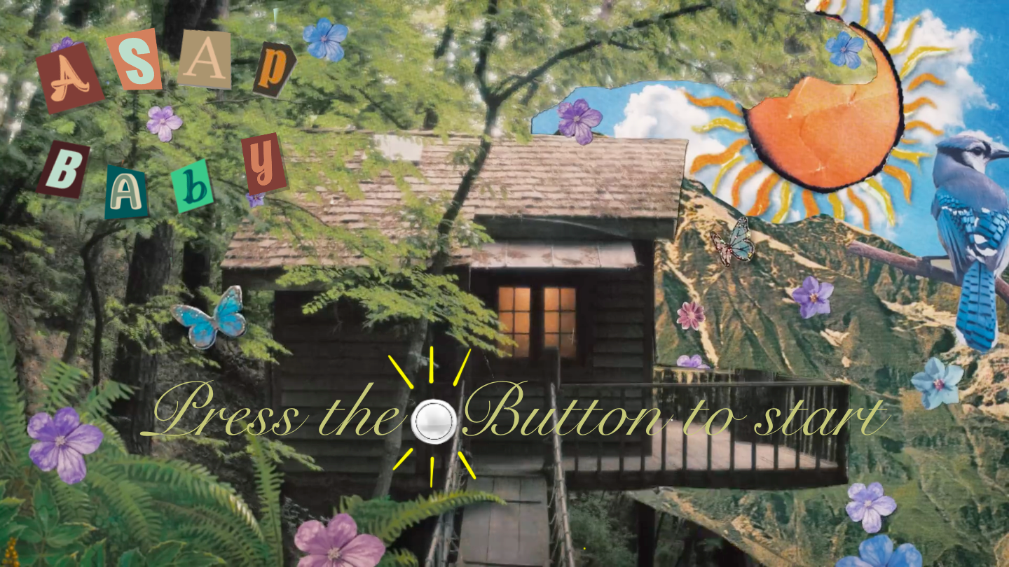
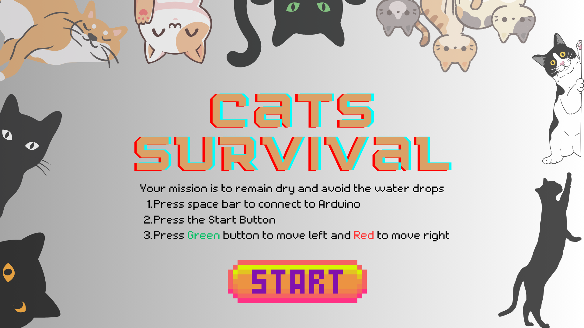
Home page:

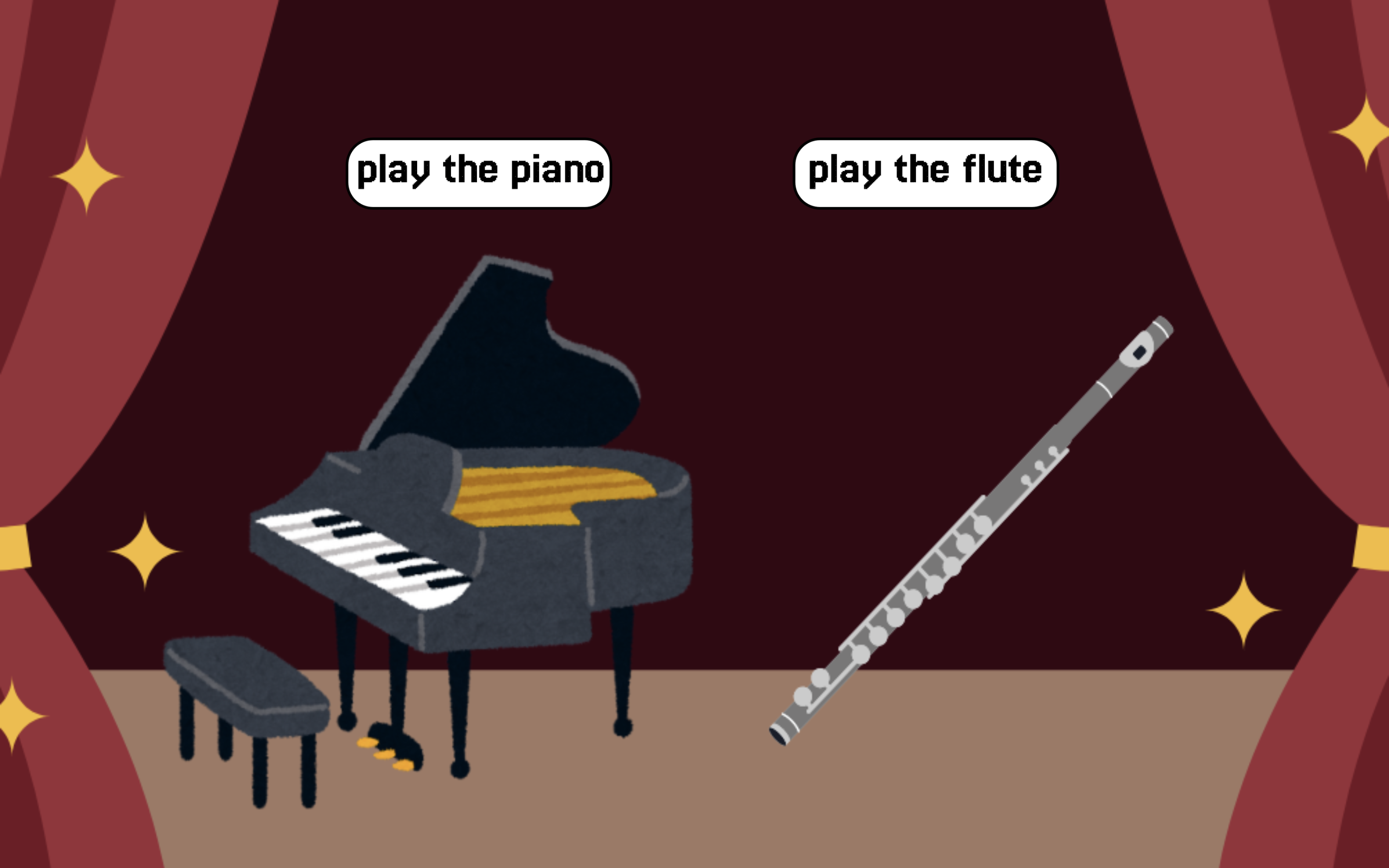
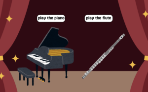
Inst page:
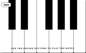
Piano page:
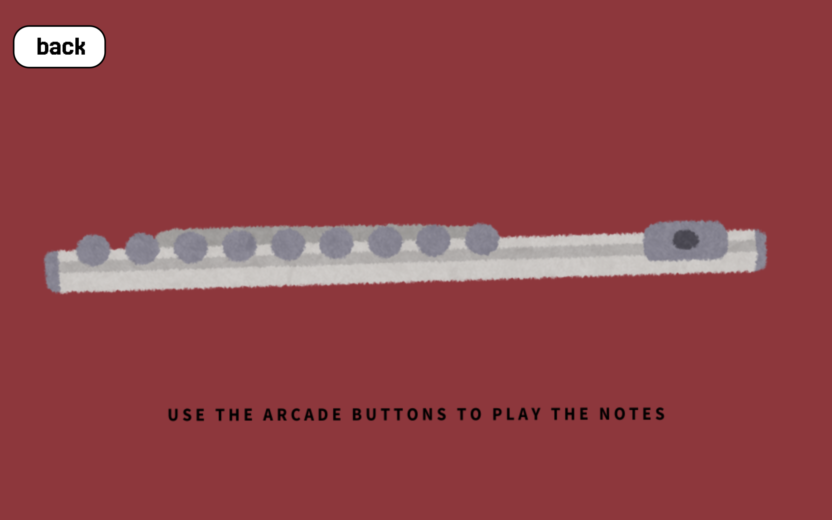
Flute page:
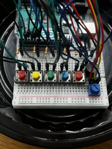
2. Arduino
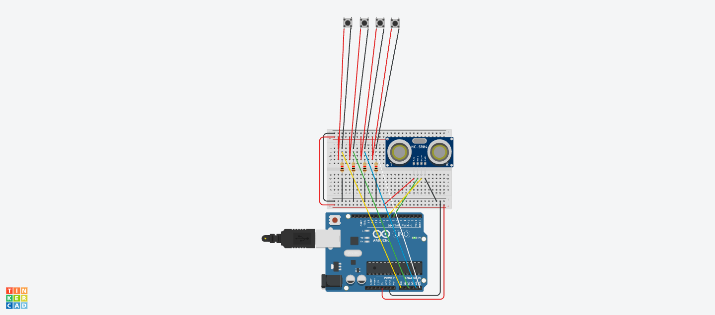
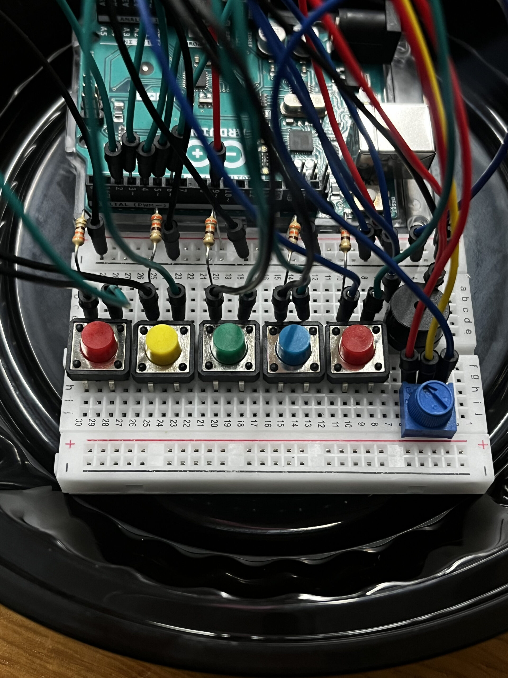
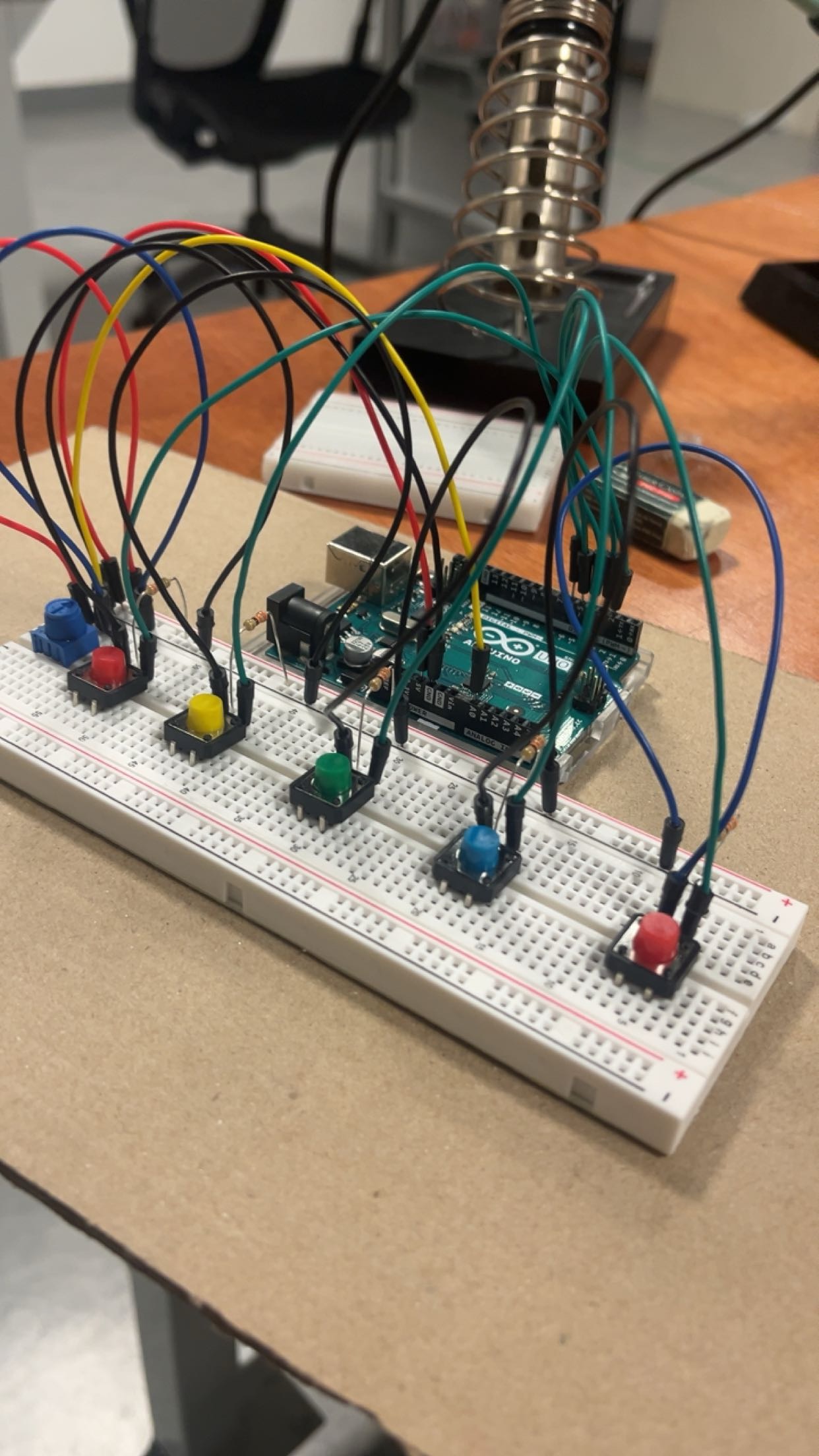
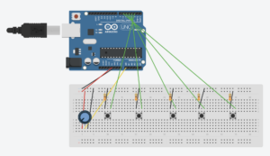
With Arduino, buttons and potentiometer were used. Each button pin was given a const int name that corresponded to its pin number and each button an int name that digital reads the information from its pin. For example, the button for the note C was plugged into pin no. 2 (const int buttonCPin) and the data collected from pin no. 2 (int ButtonC) was used to send a string of information to p5.
Furthermore, const int potPin was used to collect data from A0, which is where potentiometer was connected. Then int volume was used to analog read the potentiometer value which was sent to p5 as a string.
//Define the button pins
const int buttonCPin = 2;
const int buttonDPin = 3;
const int buttonEPin = 4;
const int buttonFPin = 5;
const int buttonGPin = 6;
const int potPin = A0;
char button = 0;


void setup() {
  // Set the button pins as input with internal pull-up resistor
  pinMode(buttonCPin, INPUT_PULLUP);
  pinMode(buttonDPin, INPUT_PULLUP);
  pinMode(buttonEPin, INPUT_PULLUP);
  pinMode(buttonFPin, INPUT_PULLUP);
  pinMode(buttonGPin, INPUT_PULLUP);
  // Initialize serial communication
  Serial.begin(9600);


  // start the handshake
  while (Serial.available() <= 0) {
    digitalWrite(LED_BUILTIN, HIGH); // on/blink while waiting for serial data
    Serial.println("0,0"); // send a starting message
    delay(300);            // wait 1/3 second
    digitalWrite(LED_BUILTIN, LOW);
    delay(50);
  }
}


void loop() {
  while (Serial.available()) {
    digitalWrite(LED_BUILTIN, HIGH); // led on while receiving data
  int volume = analogRead(potPin); // Read the potentiometer value

//creating int and string to send to p5.js
int ButtonC = digitalRead(buttonCPin);
int ButtonD = digitalRead(buttonDPin);
int ButtonE = digitalRead(buttonEPin);
int ButtonF = digitalRead(buttonFPin);
int ButtonG = digitalRead(buttonGPin);

  Serial.println(String(ButtonC) + "," + String(ButtonD) + "," + String(ButtonE)+ "," +String(ButtonF) + "," + String(ButtonG)+ "," + String(volume));
  }

  }
As the code above shows, code for Arduino is comparatively short. It simply reads signal from the pins of the button and the potentiometer and creates a string to send to p5.
Aspects of the Project that I am Proud of
First, I am glad I changed from using the speaker on Arduino to the PC speaker. The sound quality was poor when projected through the small speaker on Arduino and to enhance the sound quality and user experience, I removed the Arduino speaker and used the PC speaker instead.
Second, using string to communicate data between p5 and Arduino was very convenient and helpful. If I were to use other methods, the code for both p5 and Arduino would have been longer. However, because I used strings, the data that is being sent from Arduino to p5 was concise and very organized. In this way, when I printed the data on p5, I received one array with all the information I need to run the interaction.
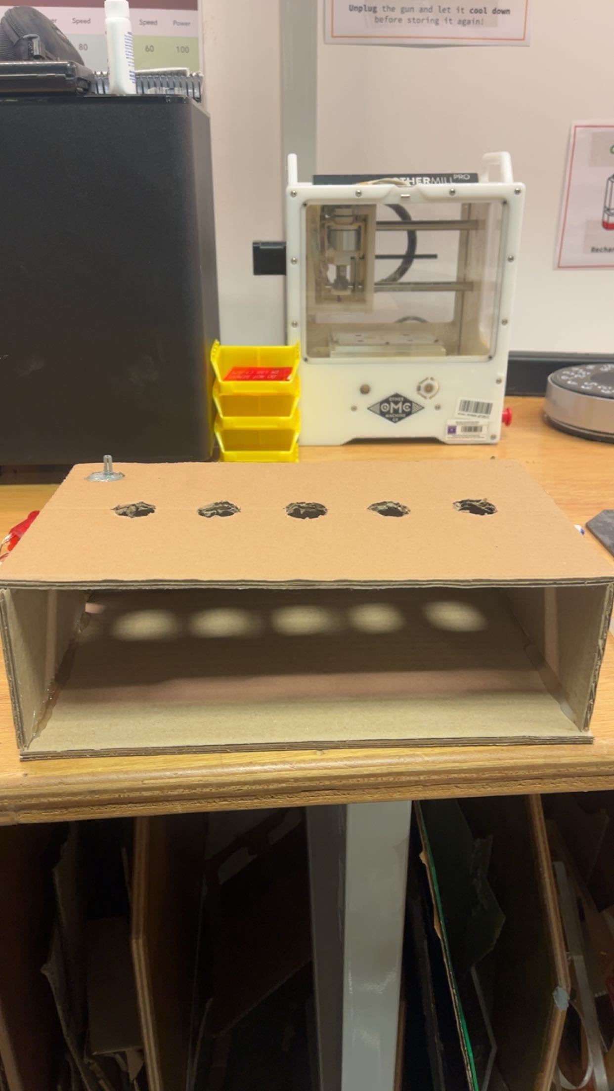
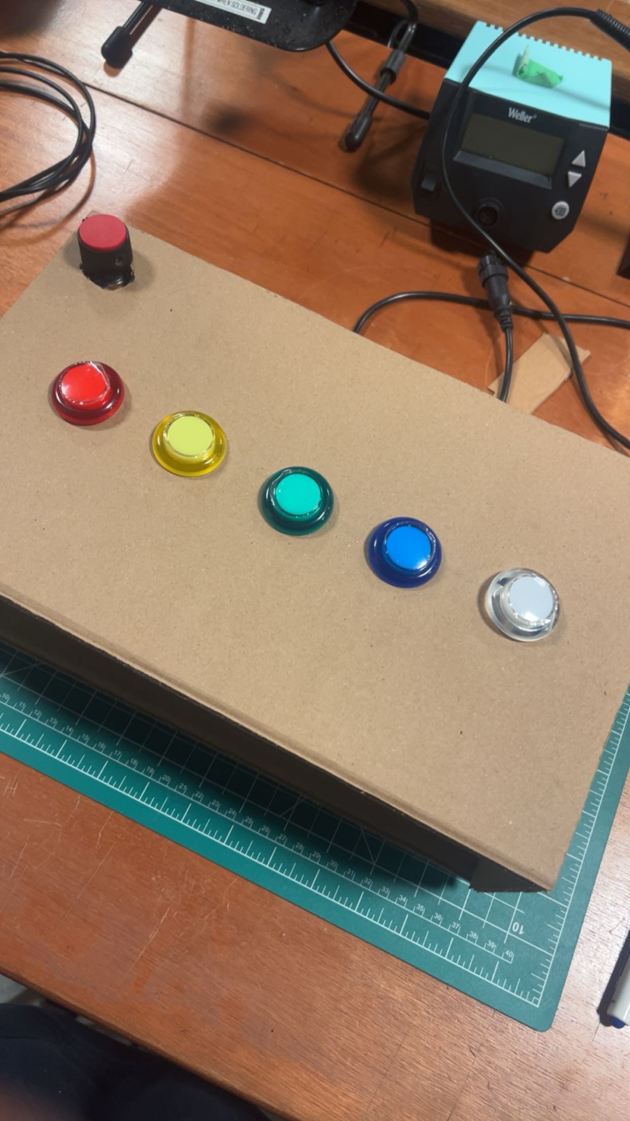
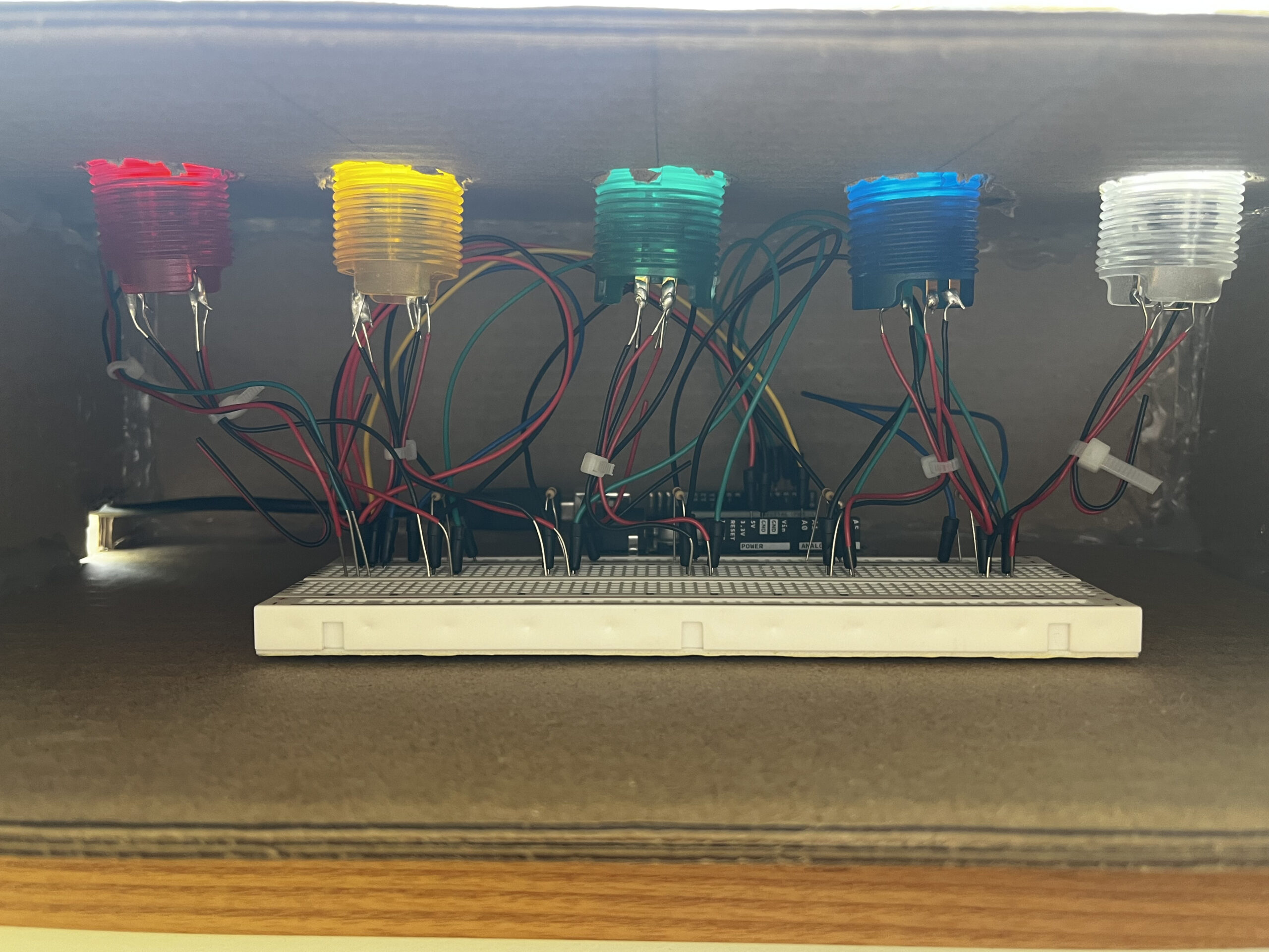
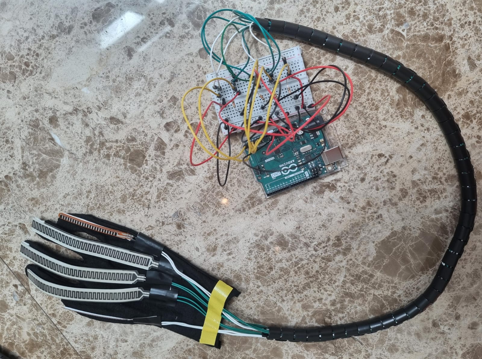
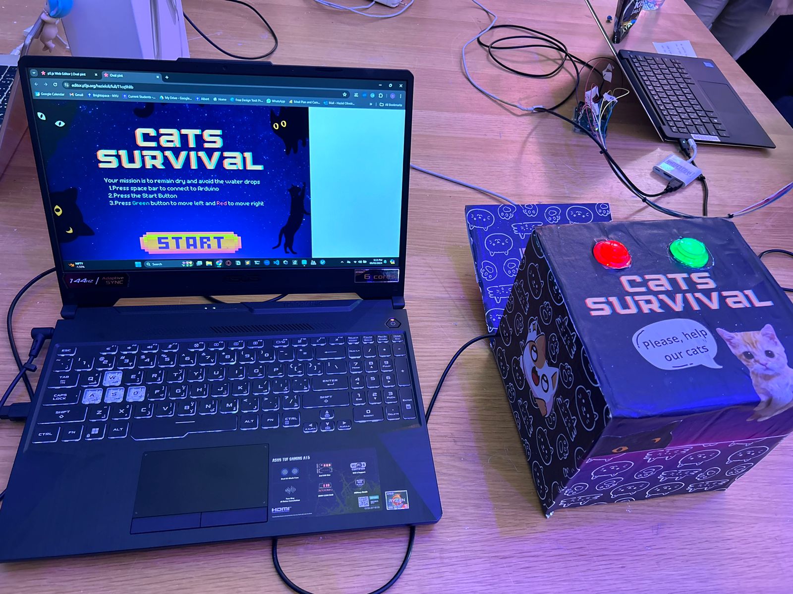
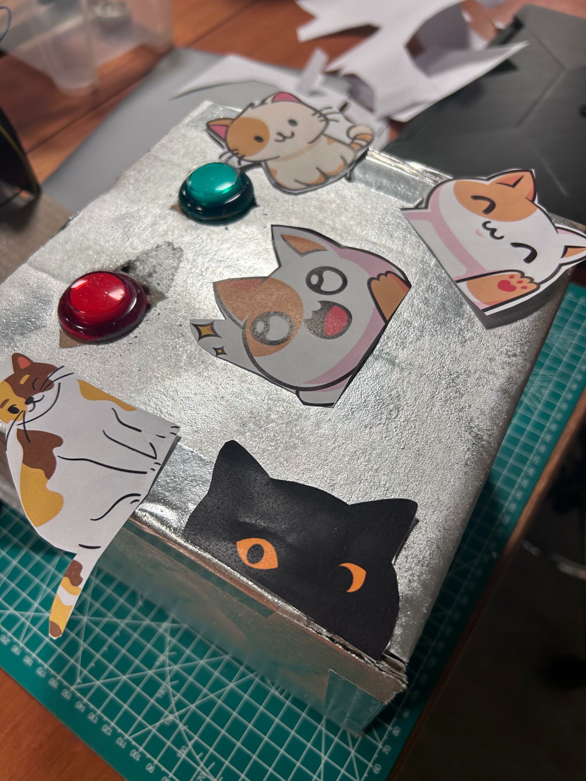
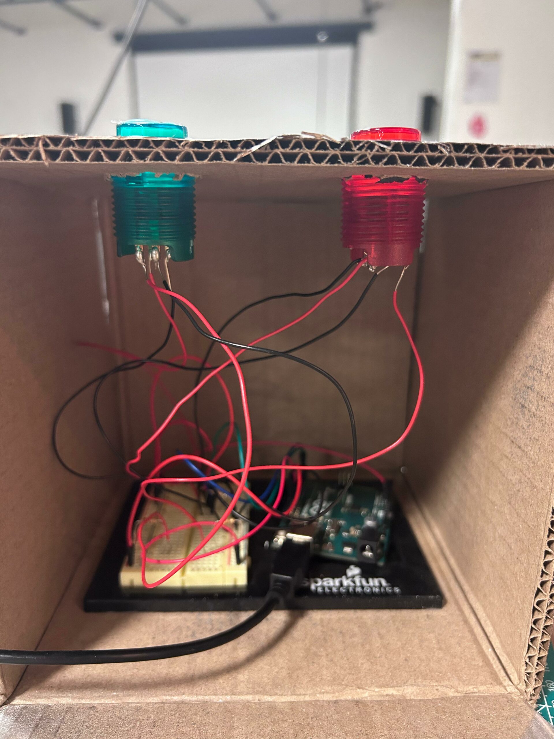
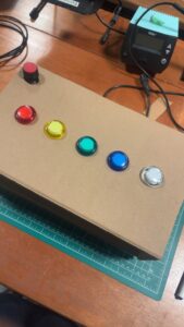
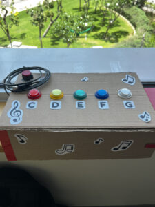
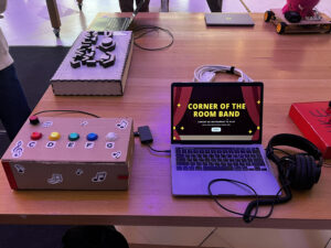
Also, I am proud of the console/button box that I created. While it is a very simple box with the buttons attached, the box is well designed to fit the theme of the project.
Below are pictures that show the process of building the box: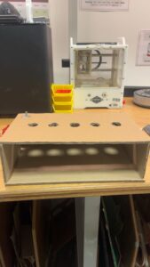
Challenged Faced and How I Overcame Them
Initially, I was going to use the potentiometer to control the frequency of the musical notes. However, I changed my plan and used it to control the volume instead because I could not find Arduino sound files that plays the flute sound. Therefore, I had to upload piano and flute sound files on p5, which prohibits the control of the frequency. Although I had to give up controlling the frequency of the sound, controlling of the volume seems like a good replacement of what the potentiometer could do.
Also, I struggled to write the code for controlling the volume on p5. Now that I have written all the code, the code for controlling the volume is actually very simple. The mistake I made was not mapping the range of the volume. From Arduino, values ranging from 0-1023 was being sent to p5 and in order for me to use this value to control the volume, I had to map it so that it fits under the range of 0-1. After I had this code written, I was able to control the volume.
Lastly, I encountered difficulties finding sound flies. At first, my plan was to have piano and guitar on the program. However, I was not able to find a good sound file for the guitar on the internet. Therefore, I changed the guitar to flute instead and successfully found sound files for the flute.
Areas for Future Improvement
For improvements, I would like to add more buttons so that the user can play more various musical notes. As of now, I only used 5 buttons for the first 5 musical notes (C, D, E, F, G). If I could add more buttons, more various sounds would be playable, enhancing user experience.
Also, I would like to add more instruments on the program. For now, there are only piano and flute but if I had more time and if more sound files were available, then I would like to add more instruments such as the drum, guitar, and trumpet.
Additionally, if I could remake the box, I would like to use laser cutting to create a more solid and neat box. Although the current box performs all the necessary tasks, it can fall apart in any moment because cardboard instead of plywood or acrylic was used. Therefore, I would like to improve the box by using laser cutting to create a more strong and durable box.
One thing that bothers me a little with my project is the delay or lag in the play of the sound files. When the user presses a button on Arduino, the corresponding sound file does not play immediately and hence creates a gap. I removed all delay functions on Arduino and checked individual sound files on p5, but for some reason, the delay between the button press and play of the file did not resolve.
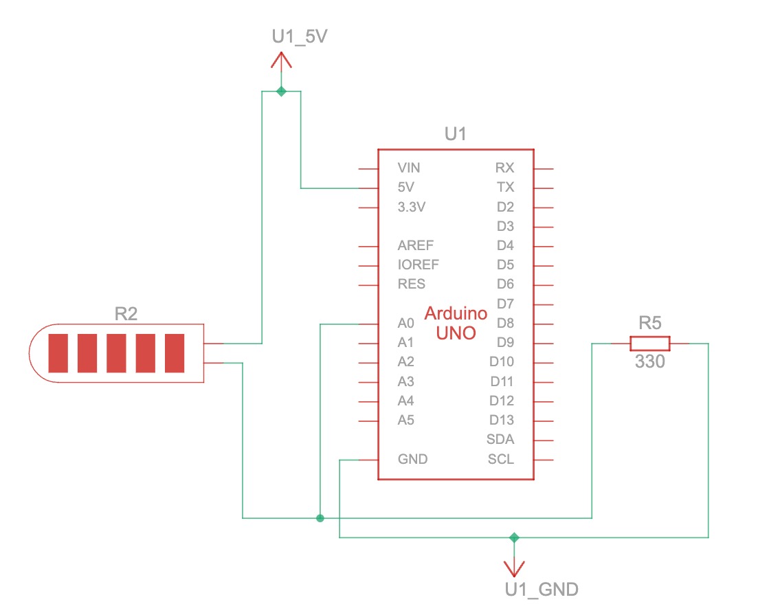
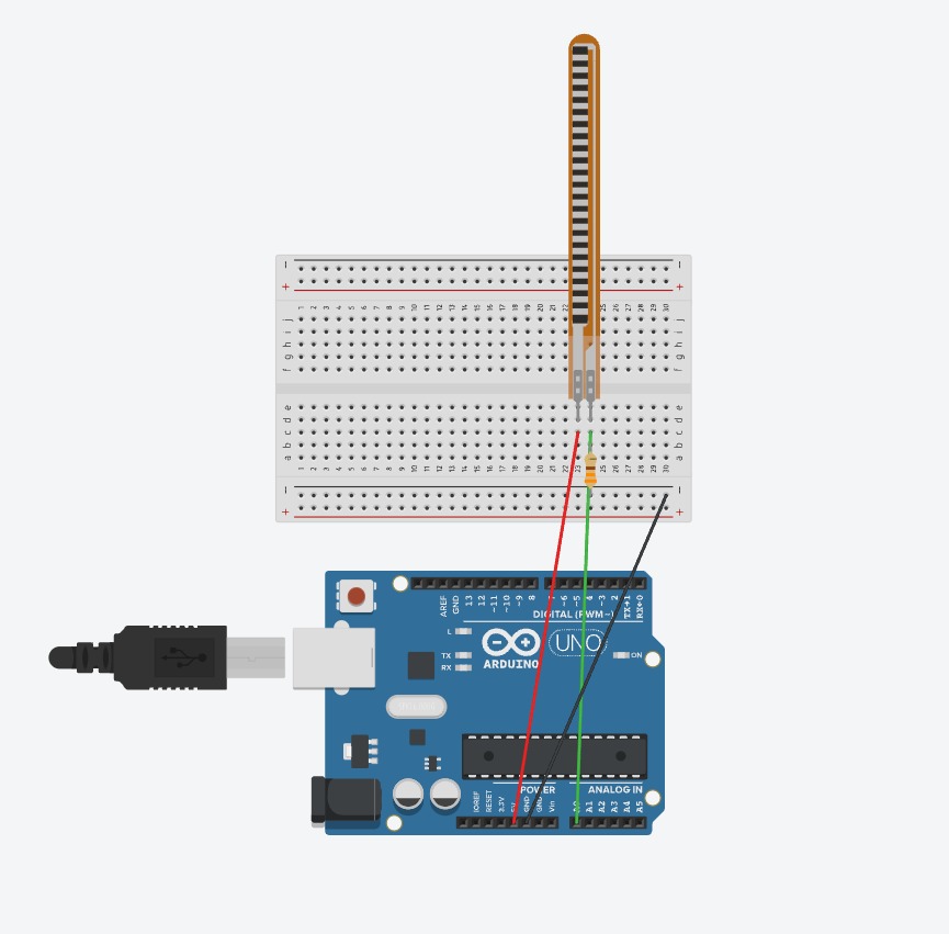
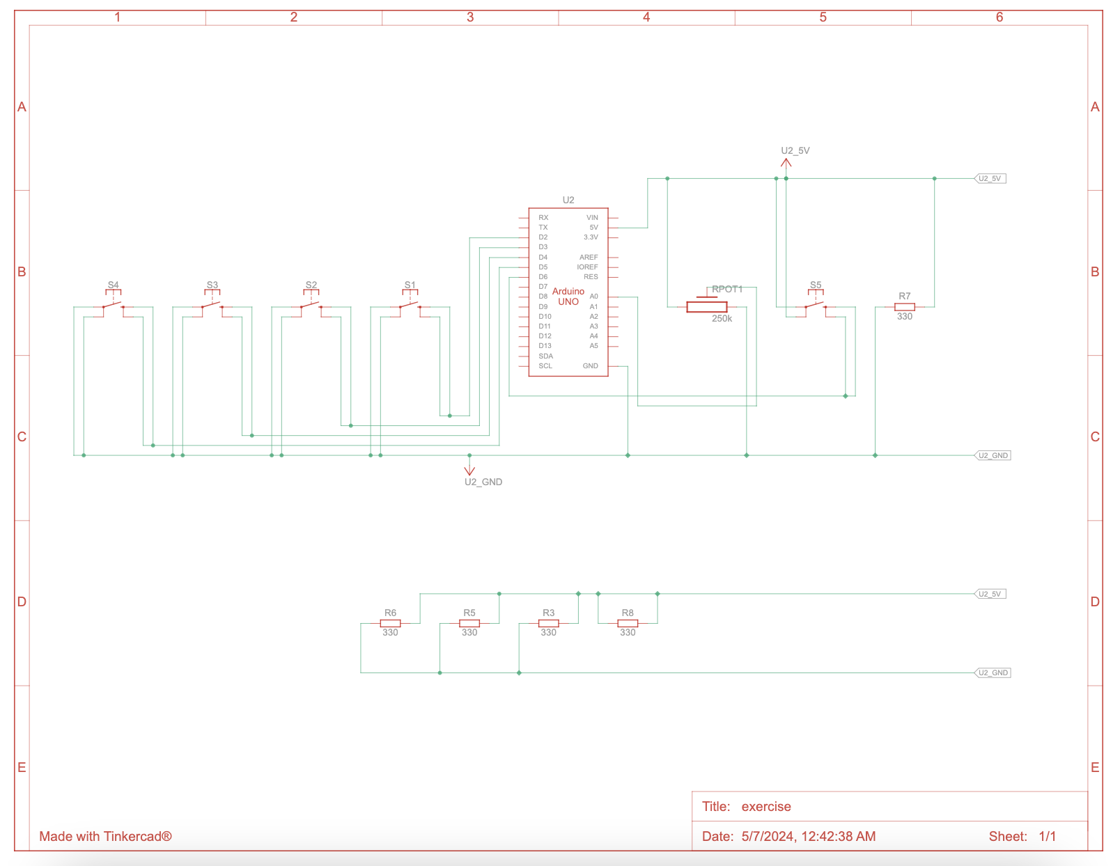
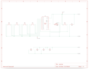
Schematics


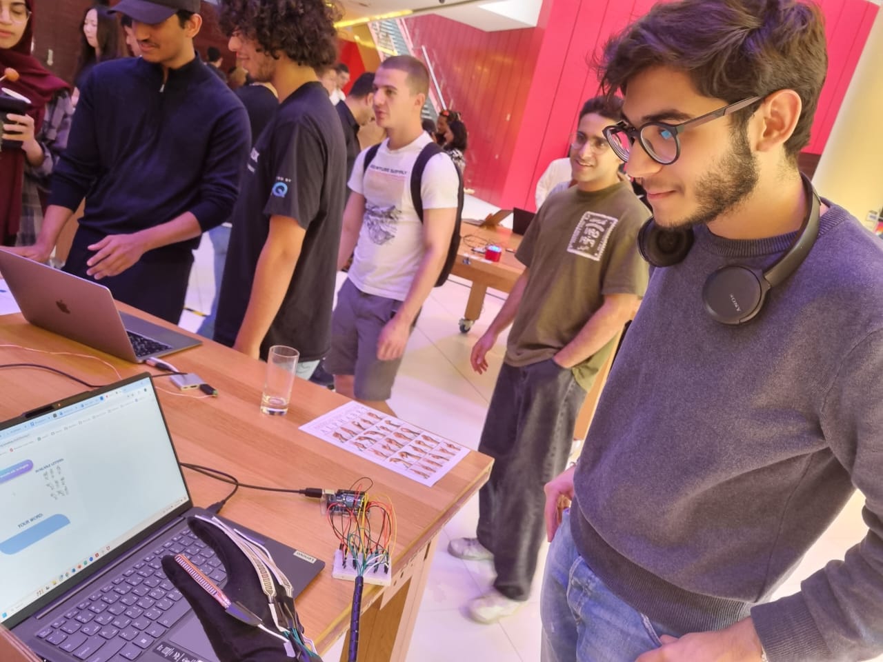
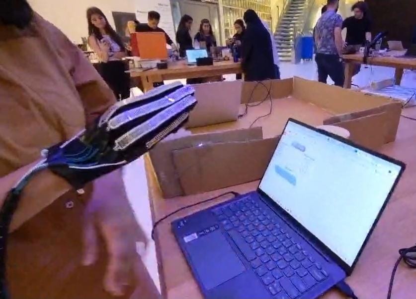
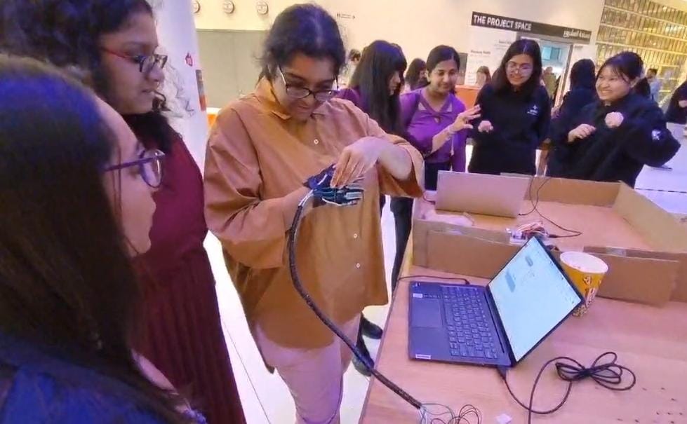
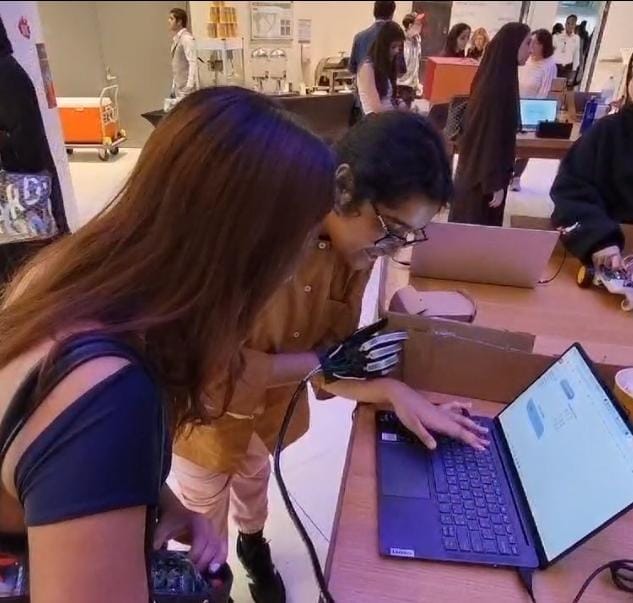
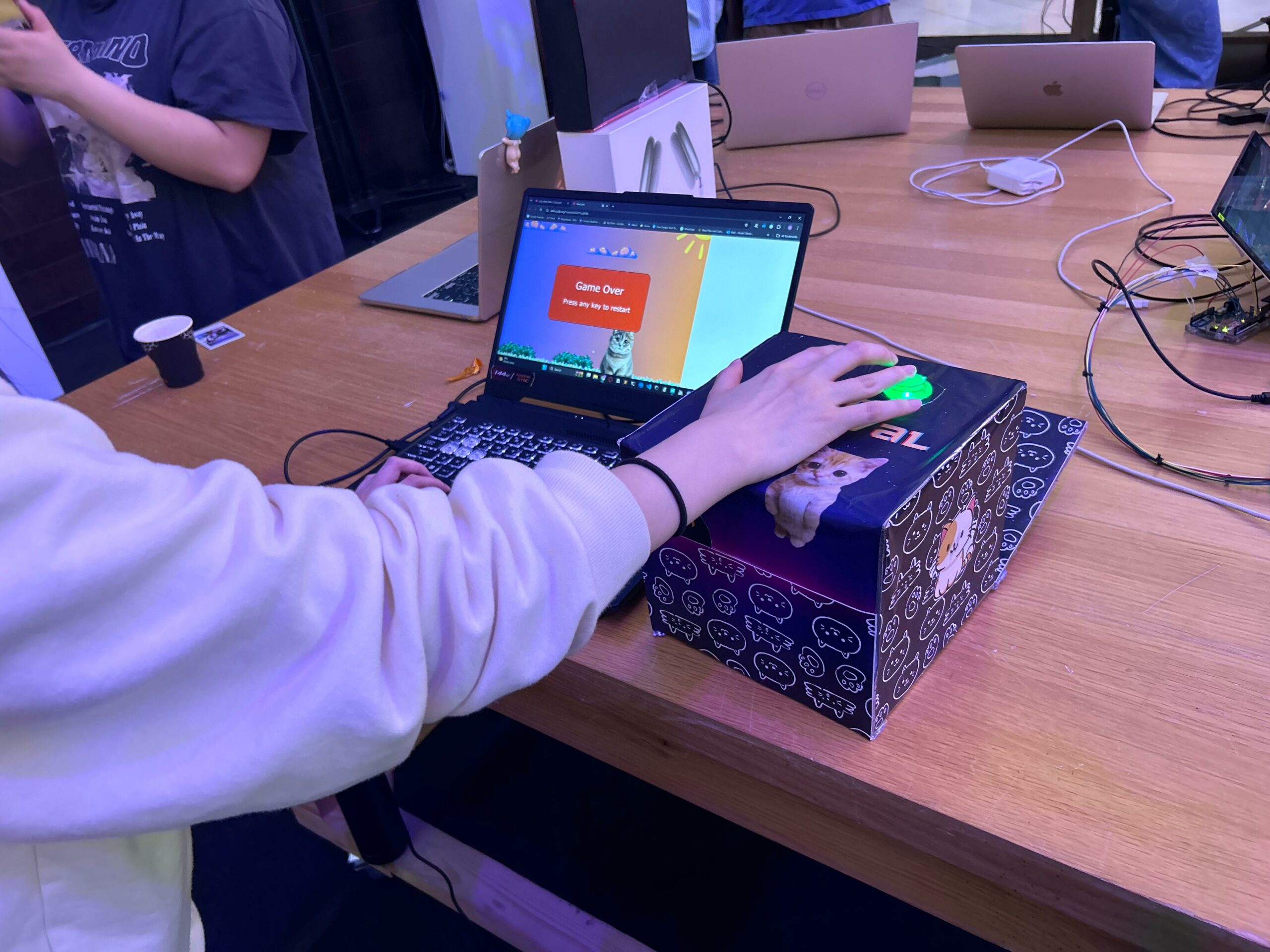
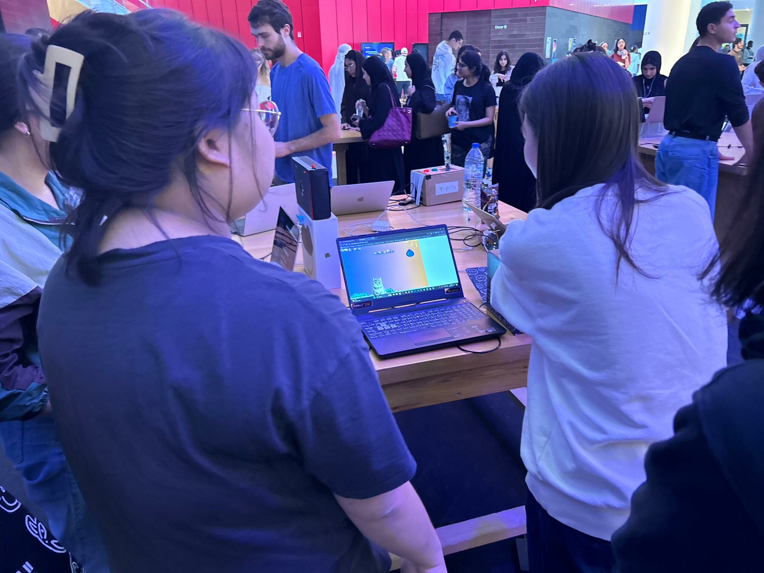
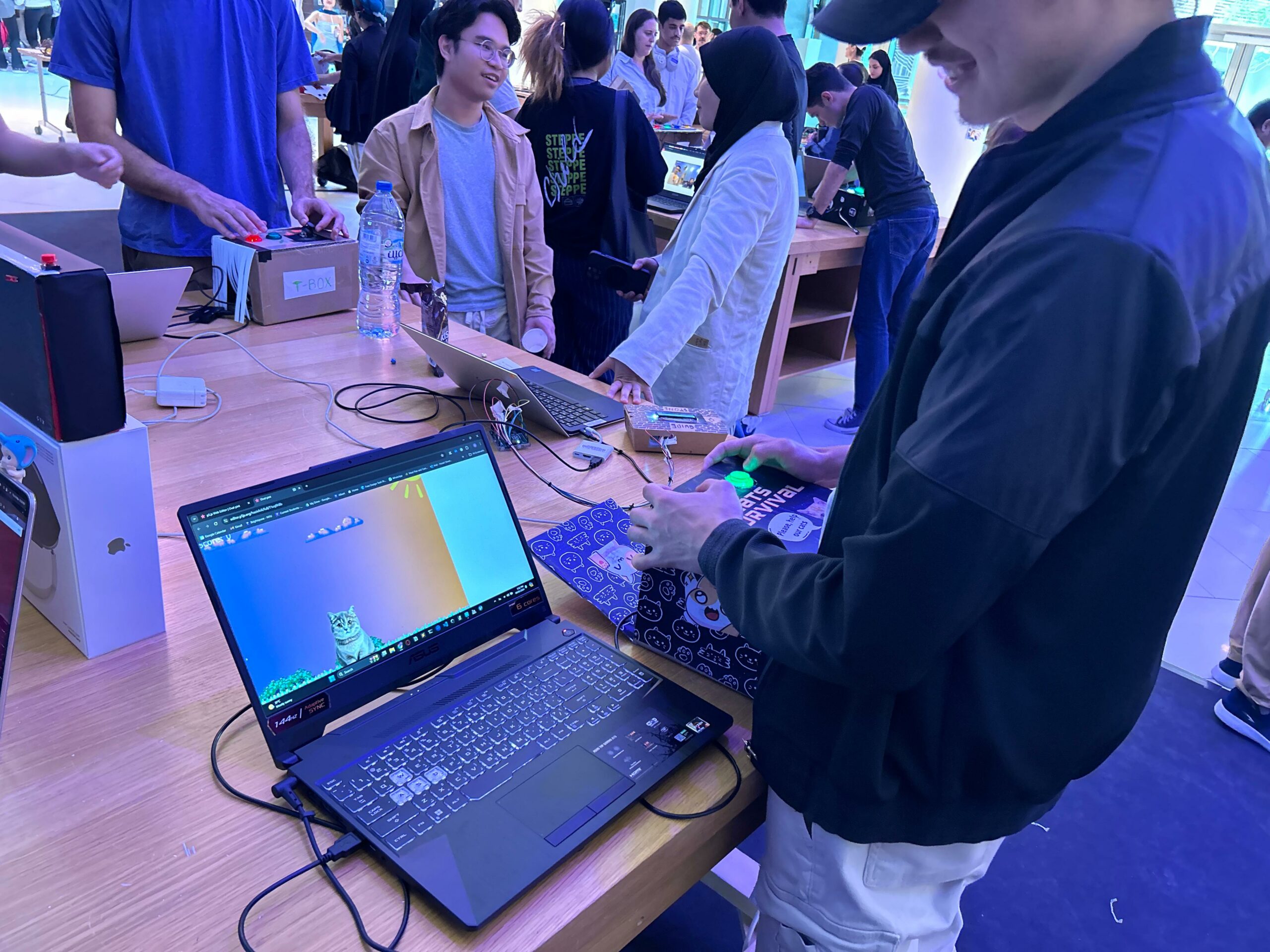
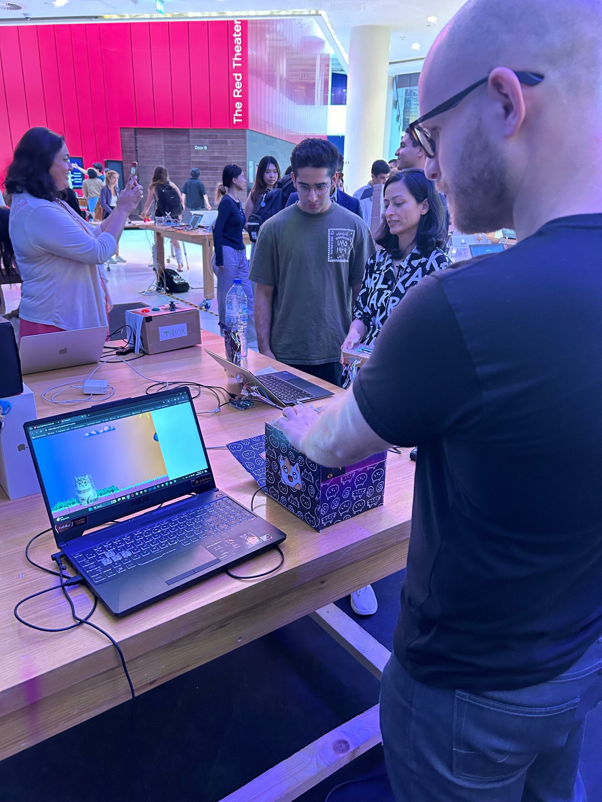
IM Showcase
IM Showcase 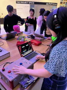
During the showcase, I was able to explain and display my final project to many people. Due to the loud noise in the arts center, I had to borrow a set of headphones so that the users can clearly hear the sounds. Many people liked the flute sound and were entertained by the interaction. I also had so much fun experiencing the works of peers. Everyone had such an interesting project and overall, the IM Showcase was a great opportunity to share our skills, talents, and projects.