During user testing, while understanding the visualization was easy, users found it hard to figure out how to interact with the visualization.
The point of error was that there was no clear indication of what to do, a major design aspect I’ve overlooked. Eventually, however, the users understand that in the arduino circuit, the photocell is able to switch the colors of the beat in accordance with the light. And, to some I had to explain exactly what the sensor did since it isn’t clear when you first try it.
The p5.Amplitude library enabled the visualization consistency with any audio input, my friends who have tested this asked to add their own music and the code worked very well 99% of the time, the remaining 1% is that this only works well with upbeat music with heavy drums.
There is definitely more area for improvement in a number of things. It would be nice if the interactivity experience was elevated to a couple of sensors which would make the experience more inclusive to the users. Also another aspect would be the color palette for the overall look, while the rainbow is definitely beautiful a color palette that is consistent would be calmer and less disturbing for the eye. Additionally, I am still in the process of designing a cover page rather than the instructions in the top left corners.
Initial Interaction Without Instructions:
– Confusion: Users were initially confused about the purpose of the buttons and how to interact with the games. The lack of clear instructions or visual cues made it difficult for them to understand the mapping between the controls and the on-screen actions.
– Exploration: Despite the confusion, users were curious and began experimenting with the buttons to see what would happen. Through trial and error, some users could figure out the basic controls for movement within the games.
Video:
Challenges:
– Button Mapping: The mapping between the button colors and the directions (especially in the Snake game) seemed arbitrary and non-intuitive to users.Game Selection: The process of navigating the menu and selecting games was not immediately apparent.
– Game Mechanics: Users familiar with Tetris and Snake could grasp the gameplay quickly, but those unfamiliar struggled to understand the objectives and rules.
Positive Aspects:
-Visual Appeal: The flip-dot display was visually engaging and drew users’ attention.
– Physical Controls: Users enjoyed the tactile experience of using physical buttons rather than a touchscreen or keyboard.
– Nostalgia Factor: For users familiar with the classic Atari games, the project evoked a sense of nostalgia and brought back positive memories.
Areas for Improvement:
– Clear Instructions: Provide concise and easy-to-understand instructions on the display or through a separate guide.
– Intuitive Controls: Consider using more intuitive button mapping or providing visual cues on the buttons to indicate their functions. For example, arrows could represent direction in the Snake game.
Areas Requiring Explanation:
– Button Functions: The purpose and mapping of each button needed an explanation, especially for the Snake game, where the color-direction association was not intuitive.
– Menu Navigation: Entering the game menu and selecting games required clarification.
– Game Rules (for unfamiliar users): A brief overview of the basic rules and objectives of Tetris and Snake would be beneficial for users who haven’t played these games before.
For the purposes of the Final Project of Introduction to Interactive Media, I was presented the challenging task of connecting Software(P5.js) and Hardware(Arduino). To achieve this, I decided to make a room that promotes sustainability and also reacts to human emotions.
Motivation
The Project was inspired by the words of my roommate who is active member of our campus’s sustainability student interest group. She constantly urges me to be more mindful of energy usage, especially my tendency to leave lights on unnecessarily. Moreover, she pointed out that I could be more emotionally present. That got me thinking: why not design a room that not only conserves energy but also tunes into human emotions? To achieve this, I incorporated a feature where both the music and lighting adapt to the mood of the person inside, creating an environment that is truly sentient and responsive.
P5.js Part
In the p5.js segment of my project, I began by integrating the camera setup. I utilized ml5.js along with face-api.js for emotion detection. Face-api.js is particularly well-suited for this task due to its ability to analyze specific facial points to ascertain emotions. The library offers a range of emotions including neutral, happy, angry, sad, disgusted, surprised, and fearful. However, for my project’s scope, I’m focusing on neutral, happy, sad, disgusted, and surprised.
I designed the system to handle the analysis for just one individual at a time. Although the camera captures all faces within its view, it processes emotions only for the first face detected. To guide the user, I placed text on the top left of the canvas that displays the detected emotion and its corresponding probability percentage. This not only informs the user about the types of expressions to test but also enhances the interactive aspect of the project.
To make the experience more engaging, I created specific graphics for each emotion using Canva. These graphics dynamically appear and float around the canvas as the detected emotion changes. Additionally, I’ve incorporated adaptive music into the p5.js environment; the music alters based on the detected emotion, thus varying the room’s ambiance to match the user’s current emotional expression. I also added a fullscreen feature that activates when the user presses ‘f’, allowing both the canvas and video to fill the entire screen.
For the Arduino component of my project, I’ve integrated three RGB LEDs and three pressure sensors. Each pressure sensor is linked to a corresponding LED, such that pressing a sensor activates its associated LED.
In p5.js, I am analyzing five expressions and converting the detection results into binary values, represented as either 1 or 0. These values are then transmitted to the Arduino. Based on the received data, if an expression is represented by a ‘1’, the corresponding RGB LED changes its color to match the detected expression.
User Testing:
Hardware and its Pictures:
This prototype of my room features a study table, a bed, and a sofa, each equipped with pressure sensors. Above, there are three LED chandeliers hanging from the ceiling.
How it Works:
Here’s how it works: Firstly, we initiate serial communication between the Arduino and the p5.js script. The music and camera activate simultaneously with the start of the p5.js sketch. Based on the expressions detected by the camera, the graphics on the display and the music will dynamically change to match your current mood.
When a user presses a pressure sensor on either the bed, chair, or sofa, the RGB LED positioned above that particular sensor will light up. Following this, as your facial expressions change, the color of the LED will also change accordingly: happiness triggers a green light, neutrality a blue light, sadness a red light, disgust a yellow light, and surprise a pink light. This creates a responsive environment that visually and audibly reflects your emotions.
Code:
Here’s the logic for activating the LED based on the sensor value and changing the colour based on the expression detected from the p5.js script.
// Light up the corresponding LED only
if (sensor1Value < 30 ) {
  digitalWrite(redLED1, Sad || disgusted || surprised);
  digitalWrite(greenLED1, Happy || disgusted);
  digitalWrite(blueLED1, Neutral || surprised);
} else if (sensor2Value < 40) {
  digitalWrite(redLED2, Sad || disgusted || surprised);
  digitalWrite(greenLED2, Happy || disgusted);
  digitalWrite(blueLED2, Neutral || surprised);
} else if (sensor3Value < 40) {
  digitalWrite(redLED3, Sad || disgusted || surprised);
  digitalWrite(greenLED3, Happy || disgusted);
  digitalWrite(blueLED3, Neutral || surprised);
}
Part of the Project that I take the most pride in:
The part I’m most proud of is how I mapped the expression values to 0 and 1, based on the percentage of the emotion detected, and then stored them in an array. This simplification made it easier to send binary values to the Arduino. However, figuring out this code took some time, as I initially tried storing emotions and their associated values in a dictionary, which didn’t work.
// maps detected expressions to a set of predefined categories and assigns a binary value based on a threshold

function mapExpressions(expressions) {
    const expressionOrder = ['neutral', 'happy', 'sad', 'disgusted', 'surprised'];
    let expressionValues = [];

    expressionOrder.forEach(expression => {
//       if value deteced is more than 50% make it 1 otherwise 0
        let value = expressions[expression] > 0.5 ? 1 : 0;
        expressionValues.push(value);
    });

    return expressionValues;
}
Difficulties and Future Improvements:
The most challenging aspect of this project was establishing the serial communication between p5.js and Arduino, which took a solid two days of trial and error. Despite trying numerous approaches, nothing seemed to work until I created a duplicate file, which then functioned flawlessly without errors. Another significant challenge was the coding aspect. Although the code itself was not particularly complex, integrating music and graphics with the face-api was time-consuming, necessitating updates to the HTML file.
Additionally, I encountered difficulties with the pressure sensors. Initially, I used piezo sensors, but they produced inconsistent readings. I switched to force sensors which provided more reliable results, although they required recalibration every five minutes, adding another layer of complexity to the project. I wrote two additional Arduino scripts to calibrate the sensors, which allowed me to run the serial monitor and check the pressure sensor values.
For future improvements, I would consider investing in better pressure sensors. Additionally, instead of relying on my computer’s speakers, I’d like to integrate an external speaker directly connected to the Arduino. This setup would enhance the overall functionality and user experience.
Code:
P5.js:
// Initializing varialbes and arrays

let faceapi;
let detections = [];
let expressionValues=[];
let video;
let canvas;
let happyEmojis=[];
let vx;
let vy;
let songs = [];
let currentSongIndex = -1;

// loading grpahics and music

function preload() {

    happyEmojis[0]= loadImage('1.png');
    happyEmojis[1] = loadImage('2.png');
    happyEmojis[2] = loadImage('3.png');
    happyEmojis[3] = loadImage('4.png');
    happyEmojis[4]= loadImage('5.png');
    happyEmojis[5] = loadImage('6.png');
    happyEmojis[6] = loadImage('7.png');
    happyEmojis[7] = loadImage('8.png');
    happyEmojis[8]= loadImage('9.png');
    happyEmojis[9] = loadImage('10.png');
    happyEmojis[10] = loadImage('11.png');
    happyEmojis[11] = loadImage('12.png');
    happyEmojis[12]= loadImage('13.png');
    happyEmojis[13] = loadImage('14.png');
    happyEmojis[14] = loadImage('15.png');
    happyEmojis[15] = loadImage('16.png');
    happyEmojis[16]= loadImage('17.png');
    happyEmojis[17] = loadImage('18.png');
    happyEmojis[18] = loadImage('19.png');
    happyEmojis[19] = loadImage('20.png');
    happyEmojis[20] = loadImage('21.png');
    happyEmojis[21] = loadImage('22.png');
    happyEmojis[22] = loadImage('23.png');

    songs[0] = loadSound('song1.mp3');
    songs[1] = loadSound('song2.mp3');
    songs[2] = loadSound('song3.mp3');
    songs[3] = loadSound('song4.mp3');
    songs[4] = loadSound('song5.mp3');
}

// Setting up the canvas and video settings
function setup() {
    canvas = createCanvas(windowWidth, windowHeight);
    canvas.id('canvas');
    video = createCapture(VIDEO);
    video.size(windowWidth, windowHeight);
    video.id('video');

//   initializes the face detection
  const faceOptions = {
    withLandmarks: true,
    withExpressions: true,
    withDescriptors: true,
    minConfidence: 0.5
  };

  //initialize the model:
  faceapi = ml5.faceApi(video, faceOptions, faceReady);

  image1 = new Emoji(happyEmojis[0],random(0,width-250),0,1,1);
  image2 = new Emoji(happyEmojis[1],random(0,width-250),0,0.5,1);
  image3 = new Emoji(happyEmojis[2],random(0,width-250),0,0.5,1);
  image4 = new Emoji(happyEmojis[3],random(0,width-250),0,1,1.5);
  image5 = new Emoji(happyEmojis[4],random(0,width-250),0,1,0.5);
  image6 = new Emoji(happyEmojis[5],random(0,width-250),0,1,1);
  image7 = new Emoji(happyEmojis[6],random(0,width-250),0,1,1.5);
  image8 = new Emoji(happyEmojis[7],random(0,width-250),0,1,0.5);
  image9 = new Emoji(happyEmojis[8],random(0,width-250),0,2,1);
  image10 = new Emoji(happyEmojis[9],random(0,width-250),0,1,1.5);
  image11 = new Emoji(happyEmojis[10],random(0,width-250),0,1,0.5);
  image12 = new Emoji(happyEmojis[11],random(0,width-250),0,1,1.5);
  image13 = new Emoji(happyEmojis[12],random(0,width-250),0,2,1);
  image14= new Emoji(happyEmojis[13],random(0,width-250),0,1,2);
  image15= new Emoji(happyEmojis[14],random(0,width-250),0,1,1.5);
  image16= new Emoji(happyEmojis[15],random(0,width-250),0,1,1.5);
  image17 = new Emoji(happyEmojis[16],random(0,width-250),0,1,1);
  image18 = new Emoji(happyEmojis[17],random(0,width-250),0,1,1);
  image19 = new Emoji(happyEmojis[18],random(0,width-250),0,1,1.5);
  image20 = new Emoji(happyEmojis[19],random(0,width-250),0,1,0.5);
  image21 = new Emoji(happyEmojis[20],random(0,width-250),0,1,1.5);
  image22 = new Emoji(happyEmojis[21],random(0,width-250),0,1,0.5);
  image23 = new Emoji(happyEmojis[22],random(0,width-250),0,1,0.5);
}

// adjust canvas and video size when window is resized
function windowResized() {

    resizeCanvas(windowWidth, windowHeight);
    video.size(windowWidth, windowHeight);
}


function draw(){

  clear();
//   drawaing expressios and drawing graphics on the screen based on the detected emotion
  drawExpressions(detections, 20, 20, 14);
  if (expressionValues.length > 1 && expressionValues[1] === 1) { //
    image1.display();
    image1.update();
    image2.display();
    image2.update();
    image3.display();
    image3.update();
    image4.display();
    image4.update();
    image5.display();
    image5.update();


  }
  if (expressionValues.length > 1 && expressionValues[4] === 1) { //
    image11.display();
    image11.update();
    image12.display();
    image12.update();
    image13.display();
    image13.update();
    image14.display();
    image14.update();


  }
  if (expressionValues.length > 1 && expressionValues[3] === 1) { //
    image15.display();
    image15.update();
    image16.display();
    image16.update();
    image17.display();
    image17.update();
    image18.display();
    image18.update();
    image23.display();
    image23.update();
    // playSong(2);
  }
  if (expressionValues.length > 1 && expressionValues[2] === 1) { //
    image7.display();
    image7.update();
    image8.display();
    image8.update();
    image9.display();
    image9.update();
    image10.display();
    image10.update();

  }
  if (expressionValues.length > 1 && expressionValues[0] === 1) { //
    image6.display();
    image6.update();
    image19.display();
    image19.update();
    image20.display();
    image20.update();
    image21.display();
    image21.update();
    image22.display();
    image22.update();

  }

//   playingn songs based on the emotion detected
  if (expressionValues.length > 1 && expressionValues[1] === 1) {

    playSong(3);
  } else if (expressionValues.length > 1 && expressionValues[4] === 1) {
    // play song 1
    playSong(0);
  } else if (expressionValues.length > 1 && expressionValues[3] === 1) {
    // play song 2
    playSong(1);
  } else if (expressionValues.length > 1 && expressionValues[2] === 1) {
    // play song 3
    playSong(2);
  } else if (expressionValues.length > 1 && expressionValues[0] === 1) {
    // play song 4
    playSong(4);
  }

}

function playSong(index) {
  //stop any currently playing song
  for (let i = 0; i < songs.length; i++) {
    if (i !== index && songs[i].isPlaying()) {
      songs[i].stop();
    }
  }

  // play the selected song
  if (!songs[index].isPlaying()) {
    songs[index].play();
  }
}

// class to handle the grpahics
class Emoji {
    constructor(img,x,y,vx, vy) {
        this.img = img;
        this.x = x;
      this.y = y;
        this.vx = vx;
        this.vy = vy;
    }

    update() {
        this.x += this.vx;
        this.y += this.vy;
        // check for canvas boundaries
        if (this.x < -130 || this.x > width -200) this.vx *= -1;
        if (this.y < -110 || this.y > height -150) this.vy *= -1;
    }
// display the graphics
    display() {
        image(this.img, this.x, this.y, 500, 500);
    }
}

function keyTyped() {
  // $$$ For some reason on Chrome/Mac you may have to press f twice to toggle. Works correctly on Firefox/Mac
  if (key === 'f') {
    toggleFullscreen();
  }
}

// Toggle fullscreen state. Must be called in response
// to a user event (i.e. keyboard, mouse click)
function toggleFullscreen() {
  let fs = fullscreen(); // Get the current state
  fullscreen(!fs); // Flip it!
}

// Start detecting faces
function faceReady() {
  faceapi.detect(gotFaces);
}

// Got faces
function gotFaces(error, result) {
  if (error) {
    console.log(error);
    return;
  }
//now all the data in this detections
  detections = result;

//make back ground transparent
  clear();


  storeExpressions(detections);
  faceapi.detect(gotFaces);
}

// maps detected expressions to a set of predefined categories and assigns a binary value based on a threshold

function mapExpressions(expressions) {
    const expressionOrder = ['neutral', 'happy', 'sad', 'disgusted', 'surprised'];
    let expressionValues = [];

    expressionOrder.forEach(expression => {
//       if value deteced is more than 50% make it 1 otherwise 0
        let value = expressions[expression] > 0.5 ? 1 : 0;
        expressionValues.push(value);
    });

    return expressionValues;
}

// store expressions
function storeExpressions(detections) {
    if (detections.length > 0) {
//   for the first person in the list, map expressions
        let expressions = detections[0].expressions;
        expressionValues = mapExpressions(expressions);
        // console.log(expressionValues);


    }
}

// it draws the percentage of detected emotion on the left top corner of the canvas
function drawExpressions(detections, x, y, textYSpace){
  if(detections.length > 0){

    let {neutral, happy, angry, sad, disgusted, surprised, fearful} = detections[0].expressions;
    textFont('Helvetica Neue');
    textSize(14);
    noStroke();
    fill(44, 169, 225);
// uses nf(value, left, right) to format numbers
    text("Neutral:       " + nf(neutral*100, 2, 2)+"%", x, y);
    text("Happiness: " + nf(happy*100, 2, 2)+"%", x, y+textYSpace);
    text("Sad:            "+ nf(sad*100, 2, 2)+"%", x, y+textYSpace*2);
    text("Disgusted: " + nf(disgusted*100, 2, 2)+"%", x, y+textYSpace*3);
    text("Surprised:  " + nf(surprised*100, 2, 2)+"%", x, y+textYSpace*4);

  }else{
    text("Neutral: ", x, y);
    text("Happiness: ", x, y + textYSpace);
    text("Sad: ", x, y + textYSpace*2);
    text("Disgusted: ", x, y + textYSpace*3);
    text("Surprised: ", x, y + textYSpace*4);
  }
}

function keyPressed() {
  if (key == " ") {
    // important to have in order to start the serial connection!!
    setUpSerial();
  }
}

// This function will be called by the web-serial library
// with each new *line* of data. The serial library reads
// the data until the newline and then gives it to us through
// this callback function
function readSerial(data) {
  ////////////////////////////////////
  //READ FROM ARDUINO HERE
  ////////////////////////////////////
  console.log(expressionValues);
  if (data != null) {


    //////////////////////////////////
    //SEND TO ARDUINO HERE (handshake)
    //////////////////////////////////
    let sendToArduino = expressionValues[0] + "," + expressionValues[1] + "," + expressionValues[2] + ","  + expressionValues[3] + ","  + expressionValues[4] + "\n";
    writeSerial(sendToArduino);
  }
}
Arduino:
// Define LED pin constants
int redLED1 = 12;   // First RGB LED, red pin
int greenLED1 = 11; // First RGB LED, green pin
int blueLED1 = 10;  // First RGB LED, blue pin

int redLED2 = 9;    // Second RGB LED, red pin
int greenLED2 = 8;  // Second RGB LED, green pin
int blueLED2 = 7;   // Second RGB LED, blue pin

int redLED3 = 6;    // Third RGB LED, red pin
int greenLED3 = 5;  // Third RGB LED, green pin
int blueLED3 = 4;   // Third RGB LED, blue pin

// Define sensor pin constants
int sensor1 = A2;  // First sensor
int sensor2 = A3;  // Second sensor
int sensor3 = A4;  // Third sensor

void setup() {
  Serial.begin(9600);
  pinMode(LED_BUILTIN, OUTPUT);

  // Set LED pins to output mode
  pinMode(redLED1, OUTPUT);
  pinMode(greenLED1, OUTPUT);
  pinMode(blueLED1, OUTPUT);

  pinMode(redLED2, OUTPUT);
  pinMode(greenLED2, OUTPUT);
  pinMode(blueLED2, OUTPUT);

  pinMode(redLED3, OUTPUT);
  pinMode(greenLED3, OUTPUT);
  pinMode(blueLED3, OUTPUT);

  // Start the handshake
  while (Serial.available() <= 0) {
    digitalWrite(LED_BUILTIN, HIGH); // on/blink while waiting for serial data
    Serial.println("0,0"); // send a starting message
    delay(300);            // wait 1/3 second
    digitalWrite(LED_BUILTIN, LOW);
    delay(50);
  }
}

void loop() {
  while (Serial.available()) {
    digitalWrite(LED_BUILTIN, HIGH); // LED on while receiving data
    int sensor1Value = analogRead(sensor1);  // Read first sensor
    int sensor2Value = analogRead(sensor2);  // Read second sensor
    int sensor3Value = analogRead(sensor3);  // Read third sensor

    int Neutral = Serial.parseInt();
    int Happy = Serial.parseInt();
    int Sad = Serial.parseInt();
    int disgusted = Serial.parseInt();
    int surprised = Serial.parseInt();

    if (Serial.read() == '\n') {
      // Reset all LEDs
      digitalWrite(redLED1, LOW);
      digitalWrite(greenLED1, LOW);
      digitalWrite(blueLED1, LOW);
      digitalWrite(redLED2, LOW);
      digitalWrite(greenLED2, LOW);
      digitalWrite(blueLED2, LOW);
      digitalWrite(redLED3, LOW);
      digitalWrite(greenLED3, LOW);
      digitalWrite(blueLED3, LOW);

      // Light up the corresponding LED only
      if (sensor1Value < 30 ) {
        digitalWrite(redLED1, Sad || disgusted || surprised);
        digitalWrite(greenLED1, Happy || disgusted);
        digitalWrite(blueLED1, Neutral || surprised);
      } else if (sensor2Value < 40) {
        digitalWrite(redLED2, Sad || disgusted || surprised);
        digitalWrite(greenLED2, Happy || disgusted);
        digitalWrite(blueLED2, Neutral || surprised);
      } else if (sensor3Value < 40) {
        digitalWrite(redLED3, Sad || disgusted || surprised);
        digitalWrite(greenLED3, Happy || disgusted);
        digitalWrite(blueLED3, Neutral || surprised);
      }

      Serial.print(sensor1Value < 30);
      Serial.print(',');
      Serial.print(sensor2Value < 40);
      Serial.print(',');
      Serial.println(sensor3Value < 40);
    }
  }
  // Optional: Use built-in LED to indicate the system is running
  digitalWrite(LED_BUILTIN, HIGH);
  delay(50);
  digitalWrite(LED_BUILTIN, LOW);
  delay(300);
}
The reading dives into the fascinating history of how design intersects with disability, and of how focusing on design for disability doesn’t just solve immediate problems but can also inspire broader changes in the design world.
What’s really interesting about this is the idea that solving specific problems for disabled users can actually lead to major innovations that benefit everyone. It’s a powerful reminder that good design is about more than just looks or functionality; it’s about thoughtful innovation that considers all users. This perspective encourages us to think differently about design and its potential impact, pushing for high standards and creativity in all areas, including those designed for disability.
For my final project, I delved into graphic design, culminating in the creation of a cooking game called “Mansaf Teta.” This game is a symbol of Palestinian culture, centered around the preparation of a traditional dish. Named after the colloquial term for “Grandma’s Mansaf,
” it aims to encapsulate the essence of Palestinian culinary heritage.
The gameplay involves a series of interactive cooking actions, each tied
to a physical component controlled by an Arduino board. The first step is cooking the lamb, where players gauge the ideal temperature using a potentiometer. Next, stirring the “laban” (fermented dried yogurt) is simulated using one button to create a stirring motion. Finally, the addition of garnish is triggered by another button, offering players a holistic cooking experience.
My favorite part of the code involves programming the potentiometer and working with images to create a visualization of the stove, shown below:
  if (typeof val1 !== 'undefined') {
    //console.log("val1:", val1);
    // Respond to temperature
    if (val1 < 500) {
      image(toocold, 0, 0, w, h);
      print("checking here: "+valInRangeTime)
      valInRangeTime += deltaTime; // Add the time elapsed since the last frame to the timer
      if (valInRangeTime >= 2000) { // Check if val1 remains in range for more than 3 seconds
        print("going to next image")
        background(next1); // Display the image
        if (mouseIsPressed && mouseIsPressed && mouseX > w / 4 && mouseY > h / 2) {
          gameState = 3; //go to first part
        }
      }
    } else {
      // If val1 goes out of range, reset the timer
      valInRangeTime = 0;
    }
  }
}
Throughout the game-making process, I encountered challenges, especially with establishing a stable serial connection and some game logic. However, with help and guidance from professor and problem-solving skills, I managed to overcome these obstacles and bring my thoughts into a final product.
Looking ahead, I would add more to this project. This includes expanding the variety of sensors on the Arduino board to introduce more nuanced interactions and incorporating additional audio effects to heighten immersion.
Despite these challenges, I take pride in the design and color palette of the game, which I believe enhances the overall experience for players, immersing them in the rich tapestry of Palestinian culinary culture.
It was easy to come up with an overall abstract direction for the final project as I had set my mind early on to revisit the butterfly motif in different ways throughout the course. As for the actual concept behind the final, I wanted to experiment with something more centered around interaction and visuals in an installation-like manner and explore a new mode of design that I have not tapped into yet. After iterations and iterations of deliberations and conversations with Professor Aaron, I settled on creating a small piece centered around a mechanical butterfly that flutters when touched. The butterfly would be mounted atop a physical canvas, onto which p5-generated animations would be mapped and projected. The idea was to create a cohesive piece, with the hardware and the software working hand-in-hand to bring some life to a butterfly.
The mechanical butterfly is constructed out of two servo motors, with one moving at an angle supplementary to that of the other. The butterfly wings are printed on paper, laminated, cut, and attached to the servo motor blades. The butterfly “senses” touch through its antennas. My mechanical butterfly’s antennas are made of wires stripped, twisted to shape, and connected to a touch capacitive sensor. I used a box, which I wrapped with multiple layers of white paper and decorated with flowers (to look like the butterfly is in a flower field), with an opening for the Arduino and the circuit.
Interaction Design
For this piece, I wanted to emphasize designing a relatively simple interaction optimally well. The name I chose for the piece, “Pet-A-Butterfly” would be displayed to the user and would act as a signifier to touch the butterfly. The placement of the butterfly antennas opposite the user is intentional to maximize the probability that a user strokes the wires in the chance that they do not realize the antennas are to be touched. The user can interact with the piece by touching the butterfly antennas. Once touched, the butterfly wings flap, and a kaleidoscope of small p5-generated/projected butterflies emerge from beneath the butterfly and move outward in a synergistic, spiral motion.
Implementation
Arduino
The Arduino program gets the input from the sensor through the touched()method, which returns an 8-bit value representing the touch state of all pins, and sends it to the p5 sketch through serial communication. The program also gets the current status of the butterfly movement from the p5 sketch program. If the status is 1 (the butterfly is moving), the servo motor positions are updated every interval seconds. The angles of the motors are constrained to the range [25,50] and the direction of each motor’s movement alternates after each range span to achieve the flapping movement. The Arduino program also sends the current servo position to the p5 sketch to ensure the sketch only stops the butterfly animation if the servos are in the maximum angle position, ensuring the flapping stops when the wings are maximally spread.
Below is the full Arduino sketch:
/***************************************************
  This is a library for the CAP1188 I2C/SPI 8-chan Capacitive Sensor

  Designed specifically to work with the CAP1188 sensor from Adafruit
  ----> https://www.adafruit.com/products/1602

  These sensors use I2C/SPI to communicate, 2+ pins are required to
  interface
  Adafruit invests time and resources providing this open source code,
  please support Adafruit and open-source hardware by purchasing
  products from Adafruit!

  Written by Limor Fried/Ladyada for Adafruit Industries.
  BSD license, all text above must be included in any redistribution
 ****************************************************/

#include <Wire.h>
#include <SPI.h>
#include <Adafruit_CAP1188.h>
#include <Servo.h>

// Reset Pin is used for I2C or SPI
#define CAP1188_RESET  9

// CS pin is used for software or hardware SPI
#define CAP1188_CS  10

// These are defined for software SPI, for hardware SPI, check your
// board's SPI pins in the Arduino documentation
#define CAP1188_MOSI  11
#define CAP1188_MISO  12
#define CAP1188_CLK  13

#define CAP1188_SENSITIVITY 0x1F
// For I2C, connect SDA to your Arduino's SDA pin, SCL to SCL pin
// On UNO/Duemilanove/etc, SDA == Analog 4, SCL == Analog 5
// On Leonardo/Micro, SDA == Digital 2, SCL == Digital 3
// On Mega/ADK/Due, SDA == Digital 20, SCL == Digital 21

// Use I2C, no reset pin!
Adafruit_CAP1188 cap = Adafruit_CAP1188();

// Or...Use I2C, with reset pin
//Adafruit_CAP1188 cap = Adafruit_CAP1188(CAP1188_RESET);

// Or... Hardware SPI, CS pin & reset pin
// Adafruit_CAP1188 cap = Adafruit_CAP1188(CAP1188_CS, CAP1188_RESET);

// Or.. Software SPI: clock, miso, mosi, cs, reset
//Adafruit_CAP1188 cap = Adafruit_CAP1188(CAP1188_CLK, CAP1188_MISO, CAP1188_MOSI, CAP1188_CS, CAP1188_RESET);

// make a servo object
Servo servoRight;
Servo servoLeft;

// servo pposition
int position=50;
// direction of wing movement
boolean direction = true;

unsigned long previousMillis = 0;
const long interval = 100;  // interval between each wing flap in milliseconds

void setup() {
  Serial.begin(9600);
  Serial.println("CAP1188 test!");

  // Initialize the sensor, if using i2c you can pass in the i2c address
  if (!cap.begin(0x28)) {
  if (!cap.begin()) {
    while (1);
  }
  cap.writeRegister(CAP1188_SENSITIVITY, 0x5F);
  // attach the servo to pin 9
  servoRight.attach(11);
  servoLeft.attach(5);
  // write the position
  servoRight.write(180- position);
  servoLeft.write(position);
  // // start the handshake
  while (Serial.available() <= 0) {
    digitalWrite(LED_BUILTIN, HIGH); // on/blink while waiting for serial data
    Serial.println("0"); // send a starting message
    delay(300);            // wait 1/3 second
    digitalWrite(LED_BUILTIN, LOW);
    delay(50);
  }
}
}

void loop() {
  // wait for data from p5 before doing something

  while (Serial.available()) {
    uint8_t touched = cap.touched();
    int isMoving = Serial.parseInt(); // check if butterfly is still moving
    Serial.print(touched);
    Serial.print(',');
    if (isMoving == 1) {
        unsigned long currentMillis = millis();
        // check if it's time to update the wing position
        if (currentMillis - previousMillis >= interval) {
            // move servos to simulate wing flapping motion
            if (direction) {
                position += 10;
                if (position >= 50) { // flip direction twhen max angle is reached
                    direction = false;
                }
            } else {
                position -= 10;
                if (position <= 25) {
                    direction = true;
                }
            }
            // move servos in opposite directions
            servoRight.write(180-position);
            servoLeft.write(position);

            previousMillis = currentMillis;
          }
      };
    Serial.println(position); // send servc position to p5 sketch
  }
  digitalWrite(LED_BUILTIN, LOW);
}
P5
The p5 sketch is mainly responsible for triggering the animation of the smaller butterflies and for performing projection mapping which is essential for ensuring that the canvas of the sketch can always be calibrated to fit the surface of the physical box. For the latter, I made use of the p5.mapper library to create a quad map that could be calibrated to match the aspect ratios of the box’s surface dynamically. By pressing the ‘c’ key, the map’s points can be toggled and moved appropriately. This eliminated the challenge of having to align the projector height consistently across locations and manually configuring the sketch’s canvas dimensions to match the surface. After calibrating the map, the p5 program can save the map in a json file to be loaded with every program run by pressing the ‘s’ key. This code snippet of the setup()function shows how to initialize a map object and load an existing map configuration.
function setup() {
  createCanvas(windowWidth, windowHeight, WEBGL);

  // create mapper object
  pMapper = createProjectionMapper(this);
  quadMap = pMapper.createQuadMap(mapWidth, mapHeight);

  // loads calibration in the "maps" directory
  pMapper.load("maps/map.json");

  // initialize objects
  bigButterfly = new Butterfly(
    centerX,
    centerY,
    null,
    null,
    null,
    null,
    null,
    false,
    false,
    null,
    null,
    false
  ); // dummy butterfly object simulating the state of the physical butterfly
  interaction = new Interaction(); // an interaction object that handles all interaction-related animations

  // play background music in loop
  backgroundMusic.loop();
}
To implement the animation, I created an Interaction class that would start and display the animation of the butterflies in a method called play(). This method would be the argument to a function of the pMapper object called displaySketch that would handle displaying the sketch only within the map’s bounds.
// class that controls the animation trigger by the interaction
class Interaction {
  constructor() {
    this.bigButterfly = bigButterfly; // the butterfly object containing information about the physical butterfly in the center
    this.smallButterflies = []; // array that stores the smaller butterflies whose animation is triggered and displayed when signal is received from arduion
    this.numButterflies = 100; // number of small butterflies
    this.inTheCenter = this.numButterflies; // number of butterflies in the center
    // initialize randomly colored butterfly objects and append to the smallButterflies array
    let randomNum;
    for (let i = 0; i < this.numButterflies; i++) {
      randomNum = random([1, 2, 3]);
      if (randomNum == 1) {
        this.smallButterflies.push(
          new SmallButterfly(
            centerX,
            centerY,
            smallButterflySpritesheet2,
            4,
            10,
            0,
            3,
            true,
            false,
            null,
            null,
            false
          )
        );
      }
      else if (randomNum == 2){
        this.smallButterflies.push(
        new SmallButterfly(
            centerX,
            centerY,
            smallButterflySpritesheet1,
            4,
            10,
            0,
            5,
            true,
            false,
            null,
            null,
            false
          )
        );
      }
      else if (randomNum == 3){
        this.smallButterflies.push(
          new SmallButterfly(
              centerX,
              centerY,
              smallButterflySpritesheet3,
              4,
              10,
              0,
              13,
              true,
              false,
              null,
              null,
              false
            )
          );
      }
    }
  }

  play(pg) {
    /* function that controls that controls the sketch
    display -> passed to mappper object's displaySketch function
    */
    pg.clear();
    pg.push();
    pg.background(color("#B2D2A2"));
    // display instructions text only before connecting to serial
    if (textShow){
        pg.push()
        pg.fill(color("#2c4c3b"))
        pg.textFont(font);
        pg.textAlign(CENTER);
        pg.textSize(16)
        pg.text(textString, centerX+20, centerY+150);
        pg.pop()
    }

    // display butterflies
    for (let i = 0; i < interaction.numButterflies; i++) {
      pg.push();
      let angle = radians(180);
      pg.translate(
        interaction.smallButterflies[i].x,
        interaction.smallButterflies[i].y
      );
      pg.rotate(angle); // rotate butterflies 180 degrees --> better visibility for the user
      if (interaction.smallButterflies[i].moving) { // display the small butterfly if it's moving
        pg.image(interaction.smallButterflies[i].show(), 0, 0, 40, 40);
        interaction.smallButterflies[i].move(); // update movement of butterflies
      }
      pg.pop();
    }

    pg.push();

    // ellipse enclosing projected surface area of the physical butterfly
    pg.fill(color("#B2D2A4"));
    // pg.fill(color("black"))
    pg.noStroke();
    // pg.ellipse(215, 180, butterflyWidth, butterflyHeight)
    pg.pop();

    // stop butterfly from moving after a set time has elapsed and only if the
    // position of the servo is in the right direction
    if (millis() - movementTime >= interval && servoPos == 50) {
      bigButterfly.moving = false;
    }
  }
}
The movement of the butterflies follows a spiral-like path, originating outward and around the physical butterfly. It is implemented in a method of thesmallButterflyclass which inherits from a parent Butterflyclass. Here is a code snippet showing the implementation of the path movement in the smallButterflyclass :
move() {
  // update the step of the animation
  if (frameCount % this.animationSpeed == 0) {
    this.step = (this.step + this.animationDir * 1) % this.numSpritesCol;
  }

  // control the direction of the sprite movement as spritesheet must be traversed back and forth to display correct movement
  if (this.step == 0) {
    this.animationDir = 1;
  } else if (this.step == this.numSpritesCol - 1) {
    this.animationDir = -1;
  }
    // update the x and y positions based on the current angle and radius
    this.x = centerX + cos(this.angle)* this.radius + random(-0.5,0.5);
    this.y = centerY + sin(this.angle)* this.radius + random(-0.5,0.5);
    this.angle += this.angleSpeed; // increment angle to move the butterfly along a circular path
    this.radius += this.radiusSpeed; // increment the radius to move the butterfly outward


  // move back to center if butterfly exceeds the bounds
  if (this.x < minX || this.y < minY || this.x > maxX || this.y > maxY) {
    this.x = centerX;
    this.y = centerY;
    interaction.inTheCenter += 1; // butterfly is now counted as being in the center
    this.moving = false; // stop butterfly from moving

  // update angle and radius speed parameters to random values
    this.angleSpeed = random(-0.02, 0.02);
    this.radiusSpeed = random(0.5,1.2);
    this.angle = 0;
    this.radius = 0;
  }
  // flip butterfly direction depending on location in the sketch
  if (this.x < centerX && this.sprites.length > 1) {
    this.dir = 1;
  } else {
    this.dir = 0;
  }
}
When the p5 sketch receives the touch state and servo position from Arduino, it sets the moving attribute of both the butterfly object simulating the physical butterfly in the sketch and the small butterflies to true. It also starts the timer, as the physical butterfly should only stop moving after 6 seconds have elapsed and if the servos are in the right position:
function readSerial(data) {
  ////////////////////////////////////
  //READ FROM ARDUINO HERE
  ////////////////////////////////////

  if (data != null) {
    // make sure there is actually a message
    let fromArduino = data;
    // if the right length, then proceed
    if (fromArduino.length > 0) {
      // get value only when data sent from arduino is greater than 0
      fromArduino = split(trim(fromArduino), ",");
      touchSensorVal = int(fromArduino[0]); // get touch sensor val
      servoPos = int(fromArduino[1]); // get servo pos
      if (touchSensorVal >= 1) { // if sensor is touched, set the bigButterfly moving attribut to true
        interaction.bigButterfly.moving = true;

        movementTime = millis(); // record starting movement time
        interaction.inTheCenter = 0;
        // move smaller butterflies
        for (let i = 0; i < interaction.numButterflies; i++) {
          interaction.smallButterflies[i].moving = true;
        }
      }
    }

    //////////////////////////////////
    //SEND TO ARDUINO HERE (handshake)
    //////////////////////////////////
    let sendToArduino;
    if (interaction.bigButterfly.moving == true) {
      sendToArduino = 1 + "\n"; // send 1 to Arduino if the butterfly is moving
    } else {
      sendToArduino = 0 + "\n"; // send 0 to Arduino if the butterfly is done with its animation
    }
    writeSerial(sendToArduino);
  }
}
Here is an embedding of the full sketch (you can press the ‘d’ key to play the animation without the signal from Arduino):
Reflections and Parts I am Proud of
My biggest concern going into this, especially as I was going to employ projection mapping, was that I would be unable to align the p5 sketch and the physical butterfly together in a cohesive manner that still looks visually pleasing. I am, thus, proud that the final product resembles what I had envisioned. I also spent a lot of time thinking of the proper mechanism to automate the wing flapping motion and where/how to place the wings. I experimented with a lot of methods, such as attaching a vertical straw/wooden stick from the middle of the wings to the servo blades, and tugging on the wings when moving down to move the wings up and down. When that proved to be unhelpful, I switched to simply attaching each wing to a blade, which, in hindsight, should have been what I experimented with first. I also love the detail of having the connection between the butterfly and the sensor be through antenna-looking sensors, resembling the sense mechanisms of an actual butterfly (thanks to Professor Aaron for pointing this out). Finally, I am proud that I managed to properly calibrate the sensitivity of the touch sensor, as it initially was too sensitive, sometimes even detecting signals even when untouched. Keeping the sensitivity in check was a major challenge that I thankfully was able to overcome to keep the interaction consistent.
Areas for Future Improvements
I think the project could definitely be enhanced in a lot of ways. Because I spent a lot of time putting the interface together, an area of future improvement could be the p5-generated animation itself. I could have different path movements triggered with every touch, for example. I had initially wanted to map an actual animated butterfly from p5 onto a blank silhouette cutout of a butterfly, controlled by the servos in the same way. Because of difficulties in mapping the software animations to the movement of the hardware, I decided to pivot toward having the central butterfly be completely in hardware form. One improvement to explore is going in that direction, where I effectively add physical objects, like flowers, on the surface of the box and map simpler, more limited animations onto them.
And here it is, the last project of the semester. Before saying anything about the project, I just want to express my gratefulness to all the students, instructors, professors and especially Professor Aaron for having an amazing, fun and challenging time during this class.
Concept
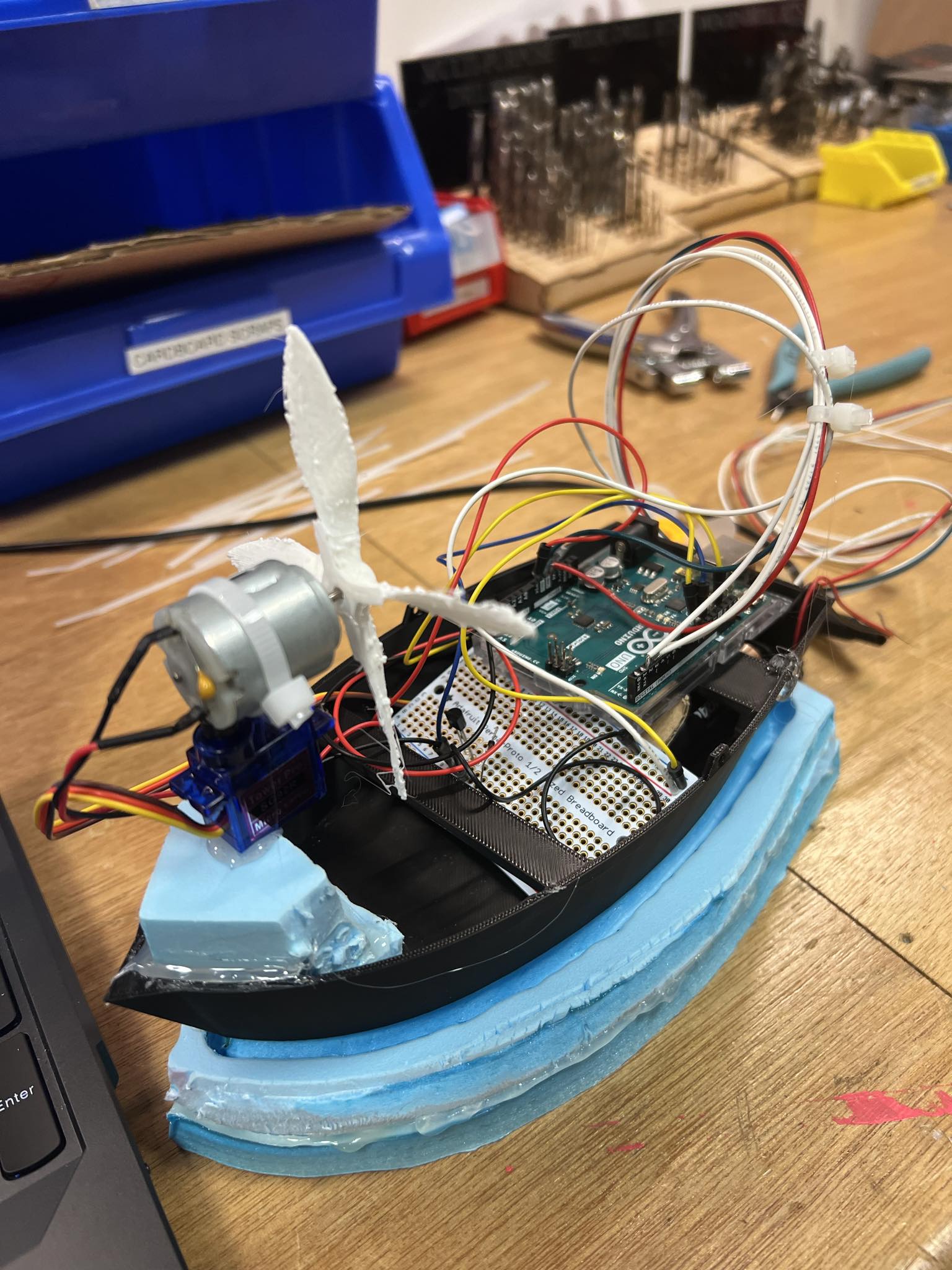
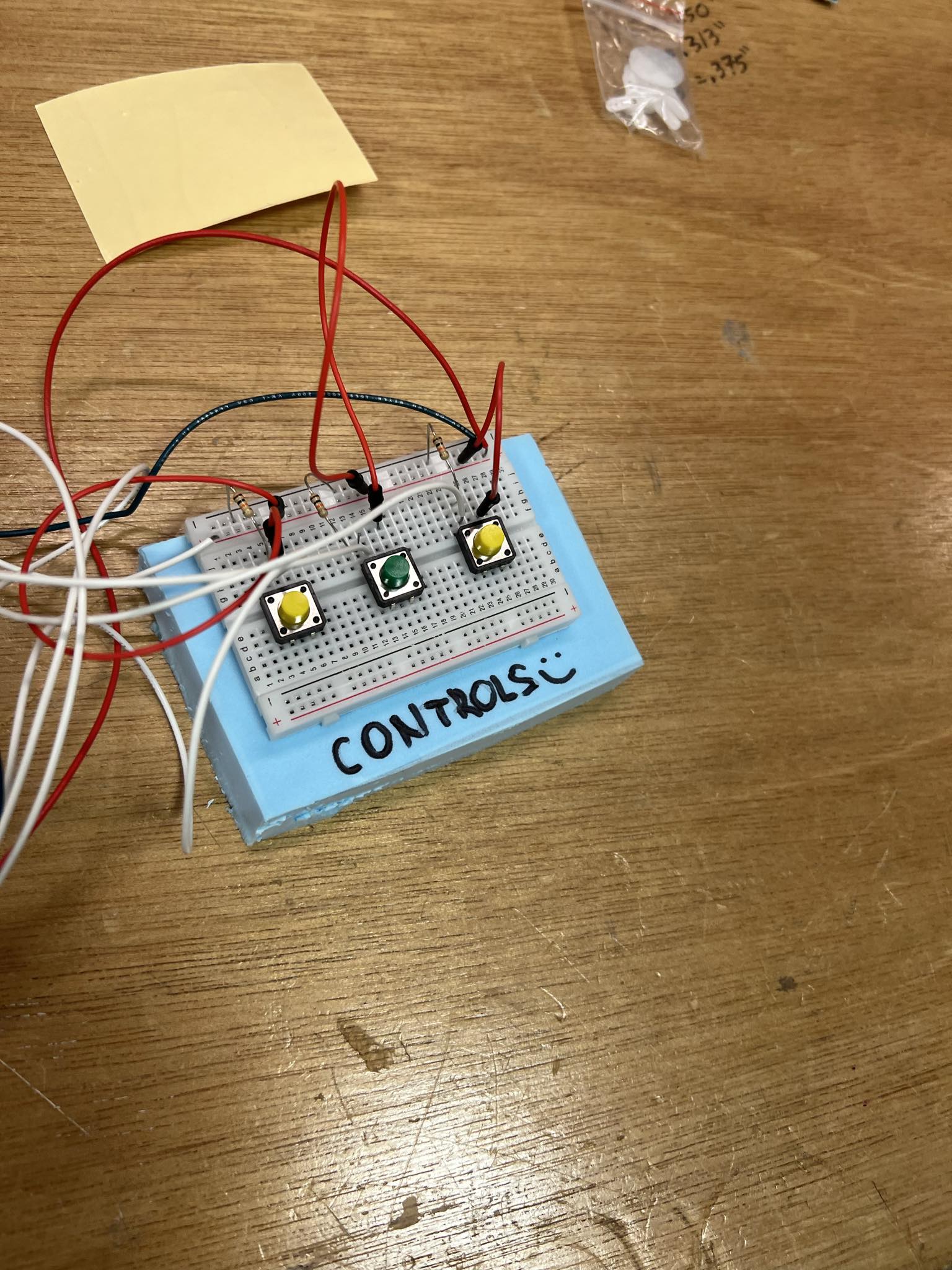
The concept of this project is pretty simple. I’m going to make you a captain of a boat for a day. SPOILER ALERT: You don’t need a license! To make this dream come true, I decided to conceptualize for the controls to be very simple, you just click to go left, right and to turn the motor boat on and off. This really takes us into intuitive design, and I believe that users would adapt very simply to this. Other that that I would need to think about the bed of the boat, the DC Motor, the Propeller, the Physics behind it and the whole placement of the Arduino. The rough sketch looked something like this:
Production:
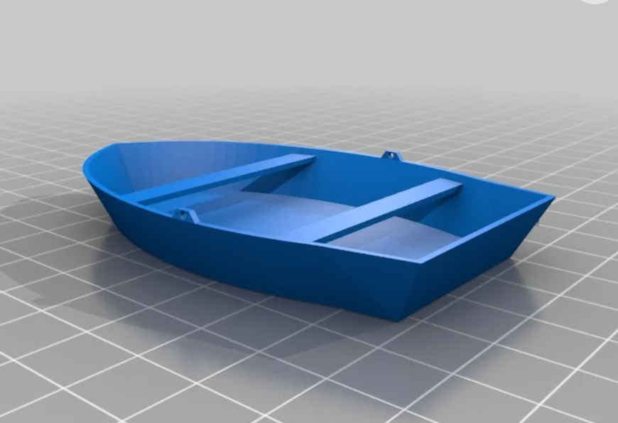
For the boat model, I found this boat bed on Thingy Verse and adjusted the dimensions so that it can find the Arduino and the breadboard, as well as the batteries. Here is how the model looked before printing:
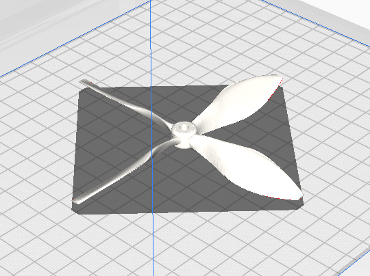
After printing it out, I looked into 3d printing a propeller which would actually be strong enough to pull the boat so I found this 3d model:
After that I placed all the parts and coded my logic for the user interaction. The code can be seen below:
#include <Servo.h>

int serialVal0 = 0;
int serialVal1 = 1;
int previousButton2State = LOW;

// Define pins for buttons, servo, and DC motor
const int button1Pin = 2; // Pin for the first button
const int button2Pin = 3; // Pin for the second button
const int button3Pin = 4; // Pin for the third button
const int servoPin = 10;  // Pin for the servo motor
const int motorPin = 11;  // Pin for the DC motor

// Define variables to store the state of buttons and motor
int button1State = 0;
int button2State = 0;
int button3State = 0;
bool motorState = false; // Motor state flag

// Create a servo object
Servo myServo;

void setup() {
  // Initialize serial communication
  Serial.begin(9600);

  // Attach servo to its pin
  myServo.attach(servoPin);

  // Set motor pin as output
  pinMode(motorPin, OUTPUT);

  // Set button pins as inputs
  pinMode(button1Pin, INPUT);
  pinMode(button2Pin, INPUT);
  pinMode(button3Pin, INPUT);

  // Start the handshake
  while (Serial.available() <= 0) {
    Serial.println("0,0"); // Send a starting message
    delay(50);
  }
}

void loop() {
  // Read the state of buttons
  button1State = digitalRead(button1Pin);
  button2State = digitalRead(button2Pin);
  button3State = digitalRead(button3Pin);

  // If button 1 is pressed, turn servo left
  if (button1State == HIGH) {
    myServo.write(120);
    serialVal0 = 80;
    delay(100); // Add a delay to avoid sending data too fast
  }

  // Toggle motor based on button 2 state
  if (button2State == HIGH) {
    if (previousButton2State == LOW) {
      motorState = !motorState; // Toggle motor state only once when the button is released
      digitalWrite(motorPin, motorState); // Set motor state
    }
  }

  // Update serialVal1 based on motor state
  serialVal1 = motorState ? 1 : 0;

  // Update previous button state
  previousButton2State = button2State;

  // If button 3 is pressed, turn servo right
  if (button3State == HIGH) {
    myServo.write(80);
    serialVal0 = 140;
    delay(100); // Add a delay to avoid sending data too fast
  }

  // Return servo to neutral position if no buttons are pressed
  if (button1State == LOW && button3State == LOW) {
    myServo.write(100); // Neutral position
    serialVal0 = 115;
    delay(100); // Add a delay to avoid sending data too fast
  }

  // Send the values of serialVal0 and serialVal1
  Serial.print(serialVal0);
  Serial.print(',');
  Serial.println(serialVal1);
}
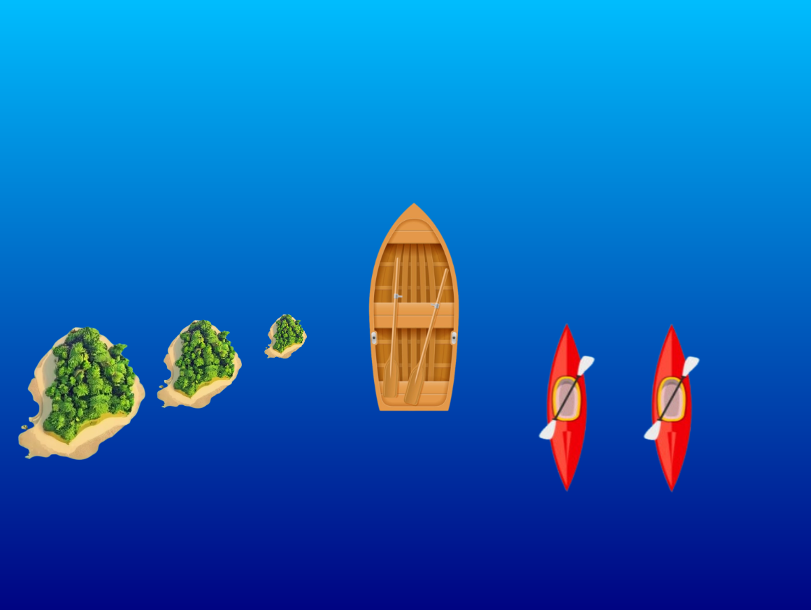
Of course this had to be connected to p5.js so I made a sketch which would provide a nice interface showing the speed and direction of where the boat is headed, it looks like this:
The p5.js code looks like this:
let servoPos; // Variable to store servo position
let motorSpeed; // Variable to store motor speed
let boatImage; // Variable to store boat image
let islandsImage1, islandsImage2, islandsImage3; // Variables to store islands images
let otherBoatsImage; // Variable to store other boats image
let serialSetUp = false; // Variable to track if serial setup is done

// Variables to store positions of objects
let islands1Y, islands2Y, islands3Y, otherBoats1Y, otherBoats2Y;

function preload() {
  // Load boat, islands, and other boats images
  boatImage = loadImage('boat.png');
  islandsImage1 = loadImage('islands.png');
  islandsImage2 = loadImage('islands.png');
  islandsImage3 = loadImage('islands.png');
  otherBoatsImage = loadImage('otherboats.png');
}

function setup() {
  createCanvas(800, 600); // Larger canvas size
  textSize(24); // Bigger font size
  // Display initial message centered on the canvas
  textAlign(CENTER, CENTER);
  setGradient(0, 0, width, height, color(0, 191, 255), color(0, 0, 128)); // Background gradient
  fill(255); // White text color
  text("Press spacebar to turn the boat motor on", width / 2, height / 2);

  // Initialize positions of objects
  islands1Y = height / 2;
  islands2Y = height / 2;
  islands3Y = height / 2;
  otherBoats1Y = height / 2;
  otherBoats2Y = height / 2;
}

function readSerial(data) {
  if (data != null) {
    // Split the incoming data by comma
    let dataArray = split(trim(data), ",");
    // If the right length, then proceed
    if (dataArray.length == 2) {
      // Parse the values as integers and store them in servoPos and motorSpeed
      servoPos = int(dataArray[0]);
      motorSpeed = int(dataArray[1]);
      console.log("Servo position: " + servoPos + ", Motor speed: " + motorSpeed);
    }
  }

  //////////////////////////////////
    //SEND TO ARDUINO HERE (handshake)
    //////////////////////////////////
    let sendToArduino = 0 + "\n";
    writeSerial(sendToArduino);
}

function draw() {
  // If serial setup is not done, return
  if (!serialSetUp) return;

  // Background gradient resembling water
  setGradient(0, 0, width, height, color(0, 191, 255), color(0, 0, 128));

  // Display boat heading status centered above boat


  // Move and draw islands images
  islands1Y += 1; // Speed of islands movement
  if (islands1Y > height) {
    islands1Y = 0; // Reset when islands moves off the screen
  }
  image(islandsImage1, 140, islands1Y, 100, 100); // Islands image on the left side

  islands2Y += 1.5; // Speed of islands movement
  if (islands2Y > height) {
    islands2Y = 0; // Reset when islands moves off the screen
  }
  image(islandsImage2, 250, islands2Y, 50, 50); // Islands image on the left side

  islands3Y += 2; // Speed of islands movement
  if (islands3Y > height) {
    islands3Y = 0; // Reset when islands moves off the screen
  }
  image(islandsImage3, 0, islands3Y, 150, 150); // Islands image on the left side

  // Move and draw other boats images
  otherBoats1Y += 1.2; // Speed of other boats movement
  if (otherBoats1Y > height) {
    otherBoats1Y = 0; // Reset when other boats moves off the screen
  }
  image(otherBoatsImage, 500, otherBoats1Y, 90, 180); // Other boats image on the right side

  otherBoats2Y += 1.8; // Speed of other boats movement
  if (otherBoats2Y > height) {
    otherBoats2Y = 0; // Reset when other boats moves off the screen
  }
  image(otherBoatsImage, 600, otherBoats2Y, 90, 180); // Other boats image on the right side

   fill(255); // White text color
  textAlign(CENTER);
  if (servoPos == 115)
    text("The boat is heading Straight!", width / 2, boatImage.height / 2 - 20); // Adjusted position
  else if (servoPos == 80)
    text("The boat is heading to the Right!", width / 2, boatImage.height / 2 - 20); // Adjusted position
  else if (servoPos == 140)
    text("The boat is heading to the Left!", width / 2, boatImage.height / 2 - 20); // Adjusted position

  // Draw boat image with rotation based on servo position
  push();
  translate(width / 2, height / 2); // Center of the screen
  rotate(radians(-90)); // Rotate to point upwards
  if (servoPos == 80) {
    rotate(radians(20)); // Rotate slightly to the right
  } else if (servoPos == 140) {
    rotate(radians(-20)); // Rotate slightly to the left
  }
  imageMode(CENTER);
  image(boatImage, 0, 0, 250, 150); // Draw boat image
  pop();

  // Display motor speed centered below boat with larger font size
  textSize(24); // Larger font size
  textAlign(CENTER);
  if(motorSpeed ==0)
    text("Motor Speed: HIGH ", width / 2, height - 20);
  else if(motorSpeed == 1)
    text("Motor Speed: LOW ", width / 2, height - 20);
}

// Function to draw a gradient background
function setGradient(x, y, w, h, c1, c2) {
  noFill();
  for (let i = y; i <= y + h; i++) {
    let inter = map(i, y, y + h, 0, 1);
    let c = lerpColor(c1, c2, inter);
    stroke(c);
    line(x, i, x + w, i);
  }
}

function keyPressed() {
  if (key == " ") {
    if (!serialSetUp) {
      setUpSerial();
      serialSetUp = true;
    }
  }
}
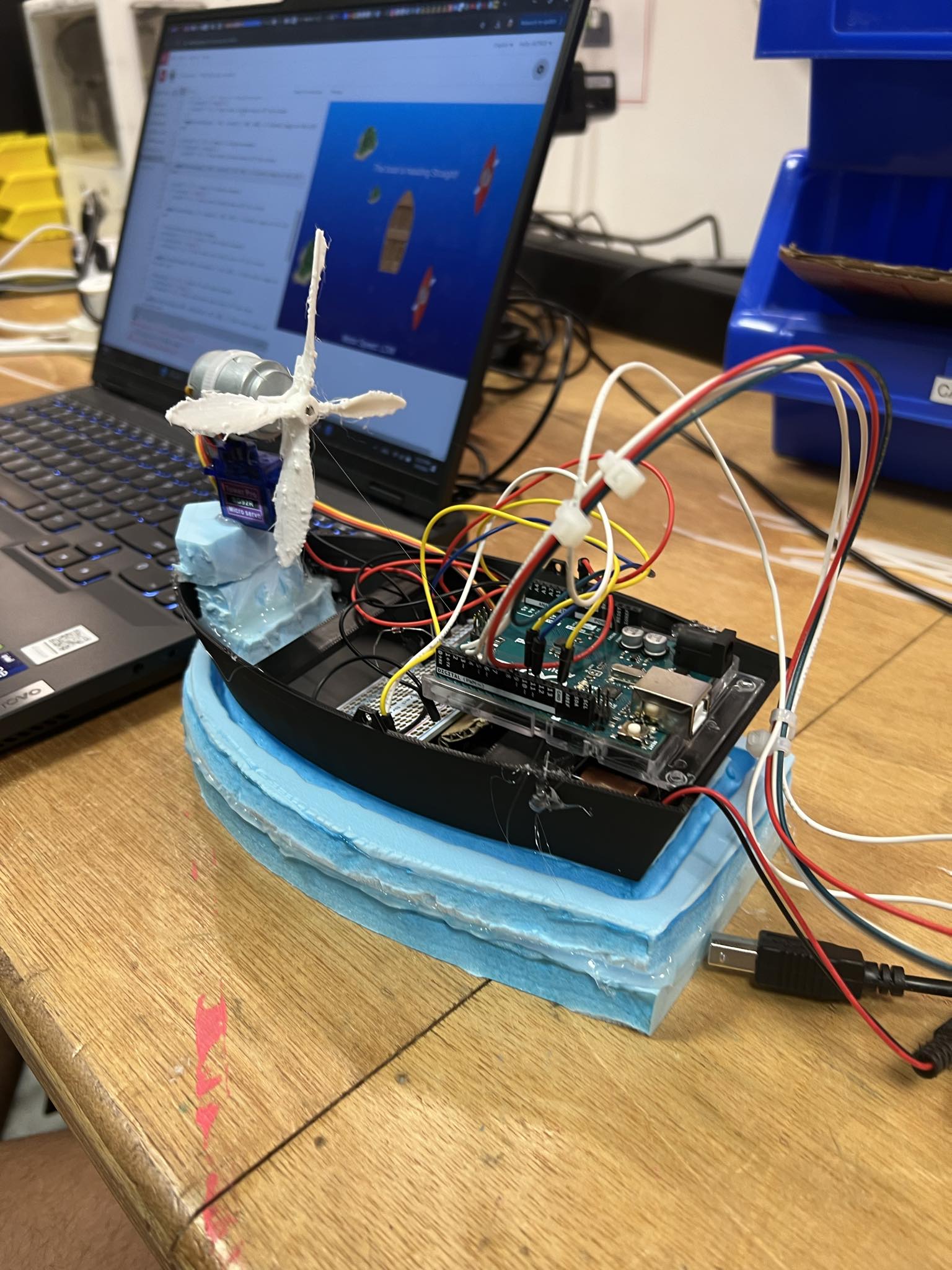
I also added some styrofoam padding on the bottom for added support and easier floating.
Here are some pictures from the production process:
And finally, here is the final video Presentation of it working:
Conclusion:
Overall this project was very fun challenging and I really think I learned a lot during the making.
Even though this is the end of the road for this class, this is only the beginning for me in exploring this area and I’m really excited of what happens next!
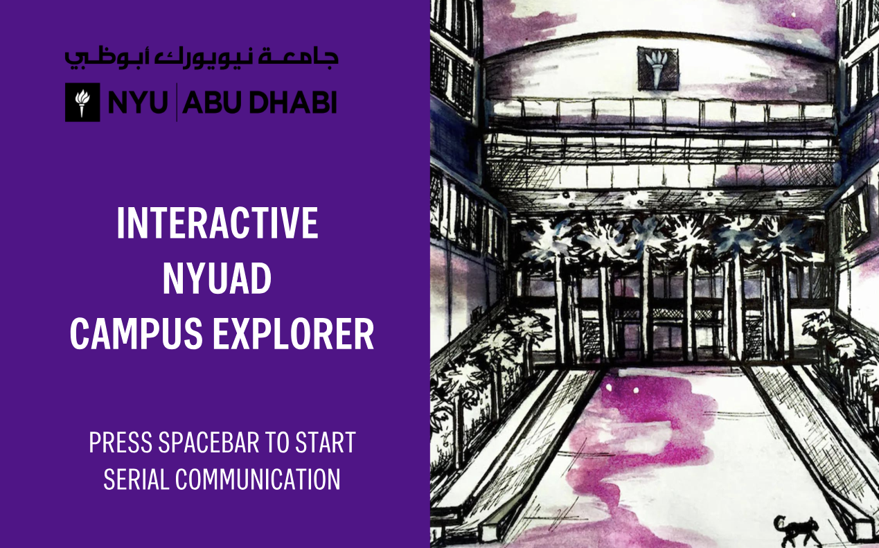
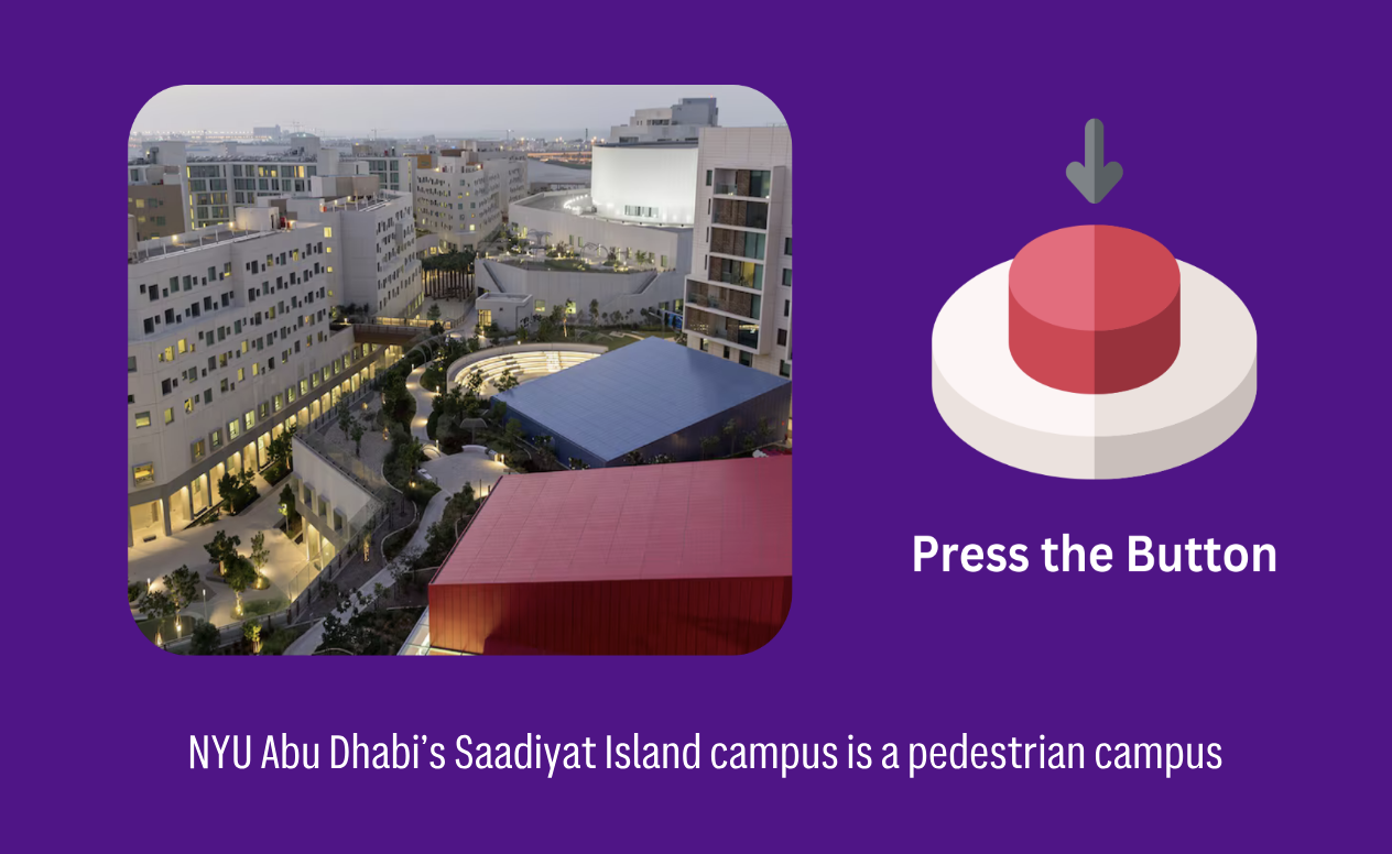
Since my midterm project was related to our campus, I wanted to work on something similar for the final project. I came up with the idea to create an interactive NYUAD campus explorer. I thought it would be a great project to showcase the beauty and resourcefulness of our campus.
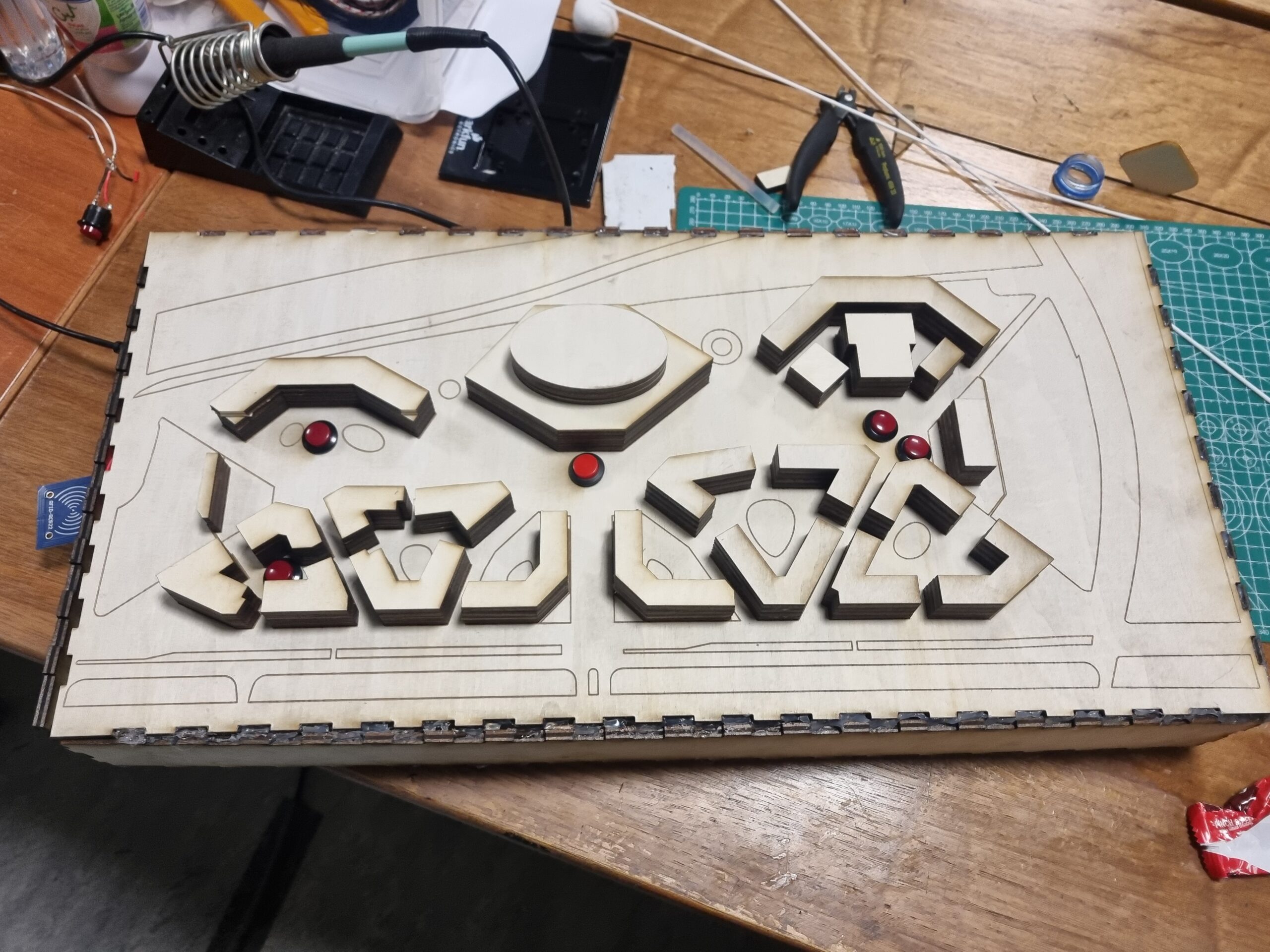
My project consists of a physical 3D model of our campus and a p5.js sketch that provides information about individual buildings.
Afterward, the user sees the ID explanation page, where the narrator welcomes them to NYUAD and explains how the virtual tour works. I used the subscription logic from this source (https://editor.p5js.org/hk3863/sketches/OSSNouhkg ), but I’ve adjusted the texts and timings to fit my project.
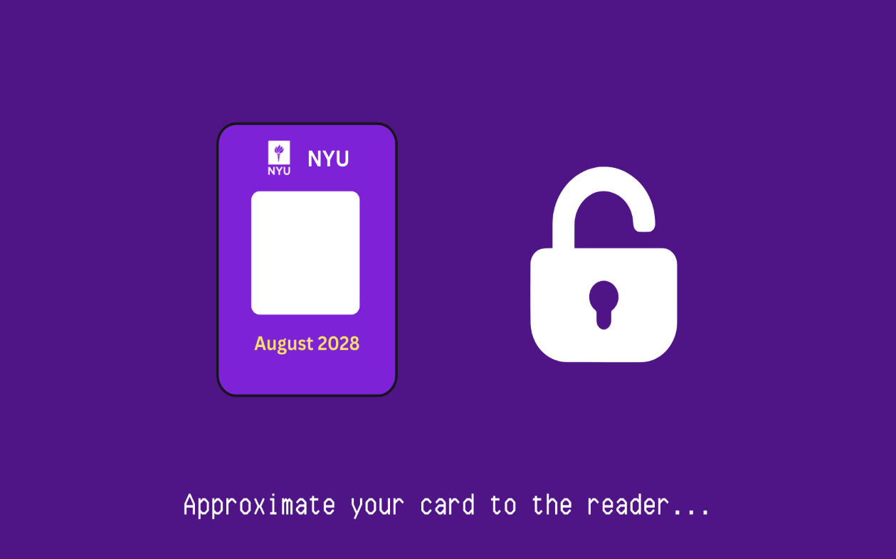
An essential and creative aspect of this project is the NYU ID card, which is required to access buildings on the NYUAD campus. I’ve used an RFID sensor to replicate the ID card.
When the user clicks on the page, they’re taken to the instruction page, where they can press buttons for specific buildings to obtain information. Here’s the interesting part: after pressing a button, they must scan their ID card to access the information, just as they would when using their ID card to enter buildings.
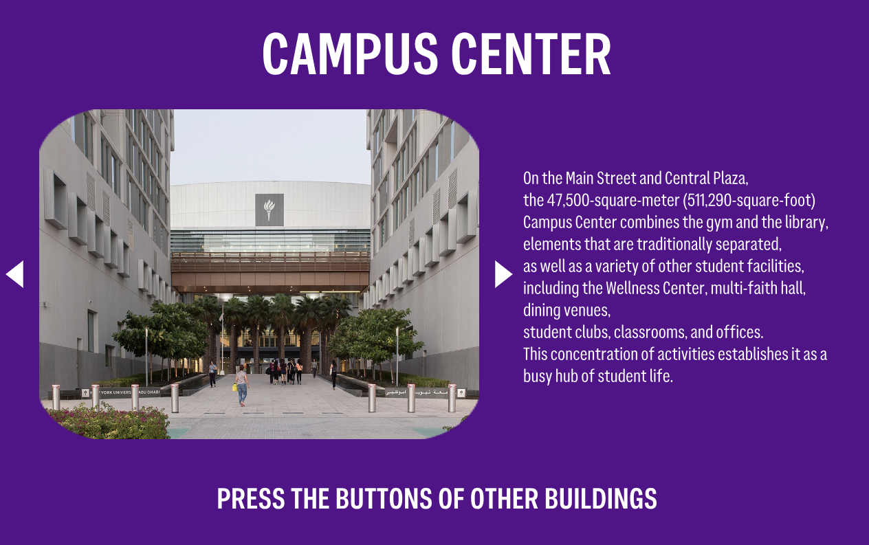
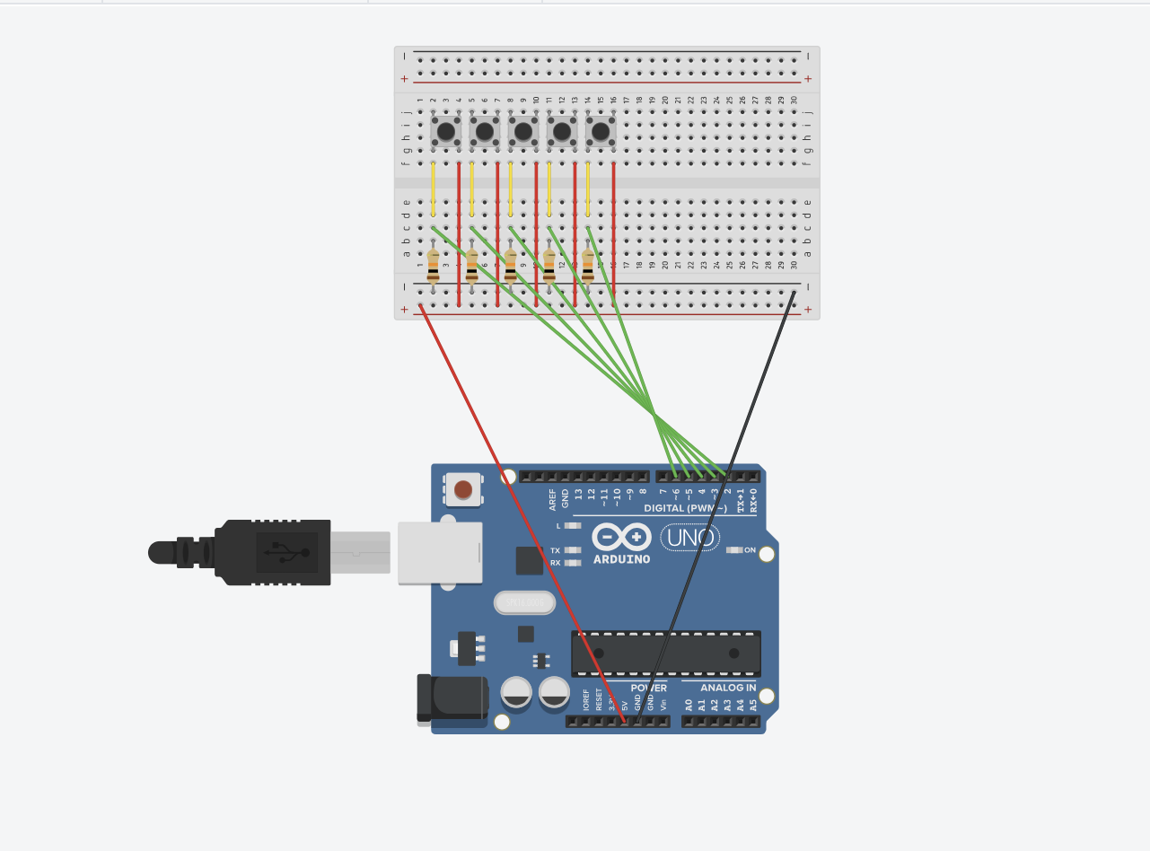
My model includes five buttons, each linked to a page with information about a building: Campus Center, Dining Halls, Research Buildings, Residences, and the Arts Center. Each page includes photographs and buttons to navigate to the next or previous photo.
My Arduino code is sending two types of data. The first is the digital input from the buttons. I’ve created arrays so that when a specific button is pressed, the button number is sent to p5.js, which then triggers the relevant function about that particular building. The second data type comes from the RFID sensor. I watched several tutorials on YouTube to understand how RFID works. In my code, you’ll see that when the tag name of my card is detected by the RFID sensor, the sensor sends a “1” to p5.js, granting access to the information.
#include <SPI.h>
#include <MFRC522.h>

// RFID Setup
#define SS_PIN 10
#define RST_PIN 9
MFRC522 mfrc522(SS_PIN, RST_PIN);  // Create MFRC522 instance

// Button Setup
const int buttonPins[] = {2, 3, 4, 5, 6};  // Digital pins for buttons
const int numButtons = sizeof(buttonPins) / sizeof(buttonPins[0]);
bool lastButtonState[numButtons] = {0};

// RFID Access Card UID
const String AUTHORIZED_CARD_UID = "70 91 42 55";
bool isAuthorized = false;
int cardAccessStatus = 0;
int buttonPressed = -1;

void setup() {
  // Initialize Serial Communication
  Serial.begin(9600);

  // Initialize RFID Reader
  SPI.begin();
  mfrc522.PCD_Init();


  // Initialize Button Pins (Input Mode, assuming external pull-down resistors)
  for (int i = 0; i < numButtons; i++) {
    pinMode(buttonPins[i], INPUT);
  }
}

void loop() {
  // Check RFID Access
  checkRFID();

  // Process Button Presses
  checkButtons();

  // Send Combined Data
  Serial.print(buttonPressed);
  Serial.print(",");
  Serial.println(cardAccessStatus);

  // Reset button state only if no button is currently pressed
  if (buttonPressed != -1) {
    buttonPressed = -1;
  }

  delay(100);  // Debounce delay
}

void checkRFID() {
  // Look for new cards
  if (!mfrc522.PICC_IsNewCardPresent()) {
    return;
  }
  // Select one of the cards
  if (!mfrc522.PICC_ReadCardSerial()) {
    return;
  }
  // Show UID on Serial Monitor
  String content = "";
  for (byte i = 0; i < mfrc522.uid.size; i++) {
    content.concat(String(mfrc522.uid.uidByte[i] < 0x10 ? " 0" : " "));
    content.concat(String(mfrc522.uid.uidByte[i], HEX));
  }

  content.toUpperCase();
  Serial.println("UID tag: " + content);

  // Check if the card is authorized
  if (content.substring(1) == AUTHORIZED_CARD_UID) {
    isAuthorized = true;
    cardAccessStatus = 1;  // Set to 1 for authorized access
    isAuthorized = false;
  } else {
    isAuthorized = false;
    cardAccessStatus = 0;  // Set to 0 for denied access
  }
}

void checkButtons() {
  for (int i = 0; i < numButtons; i++) {
    // Button logic without pull-ups: HIGH = Button pressed
    bool currentButtonState = digitalRead(buttonPins[i]) == HIGH;
    if (currentButtonState != lastButtonState[i]) {
      lastButtonState[i] = currentButtonState;
      if (currentButtonState) {
        buttonPressed = i;  // Store the pressed button index
      }
    }
  }
}
Circuit
What I Am Proud Of
I am particularly proud of creating the physical 3D model. It was my first time using Illustrator and laser cutting, and it was exciting to see the results. Through this project, I learned how to use Illustrator to turn my ideas into reality. Additionally, I’m happy I tried using a new sensor (RFID), which wasn’t covered in class. I believe it aligns well with the project’s concept.
Further Improvements
Because I didn’t have enough time, I couldn’t paint the campus model. However, with more time, I believe I could have made this model much more beautiful. Additionally, I couldn’t include information about some buildings, such as D1, so I decided to combine D2 and D1.
Overall, I am satisfied with the project’s outcome and pleased that I tried several new things and learned so much from this experience.
IM Show
A lot of people came to see my project! I really enjoyed the experience of presenting my work to others. Through this, I was able to identify some bugs I hadn’t noticed before. People loved the 3D model of the campus I created. They suggested it could be used for Marhaba or campus tours.
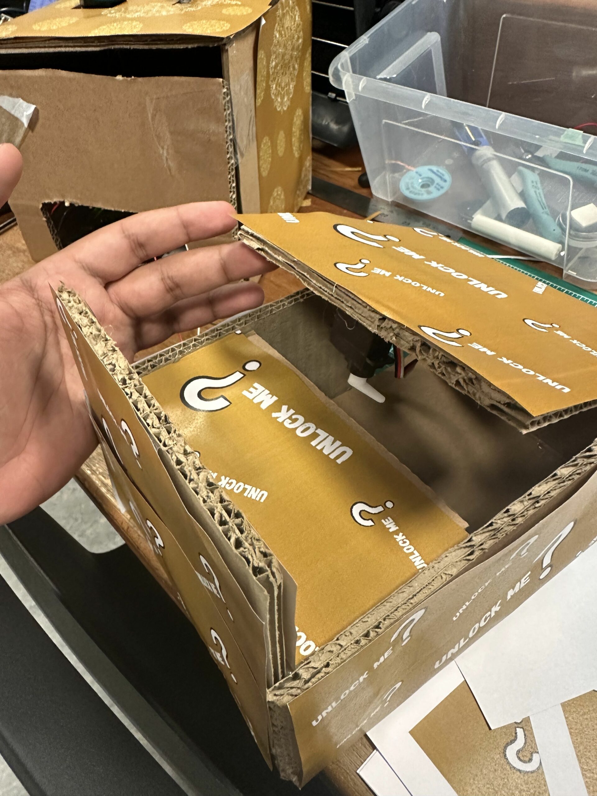
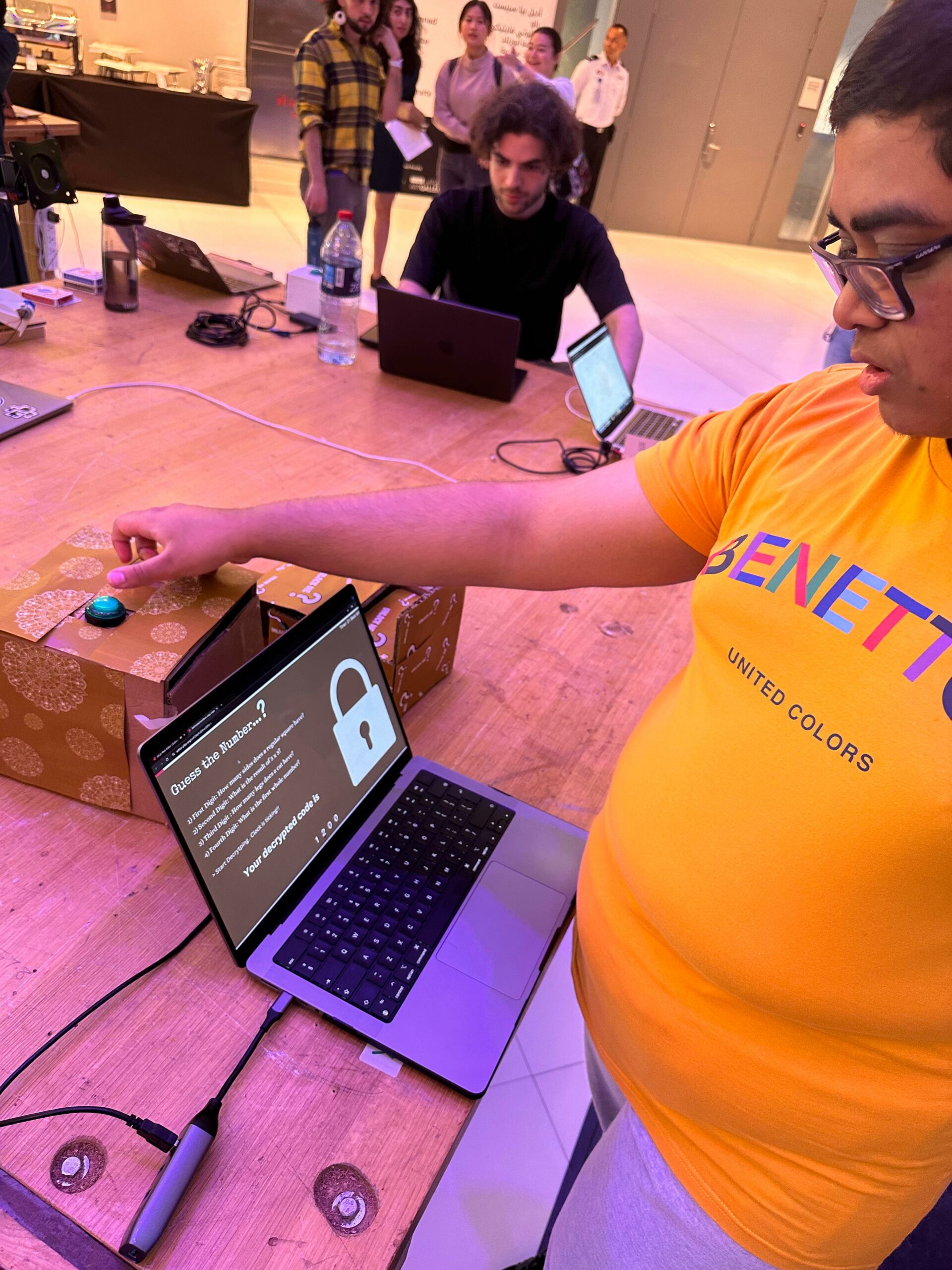
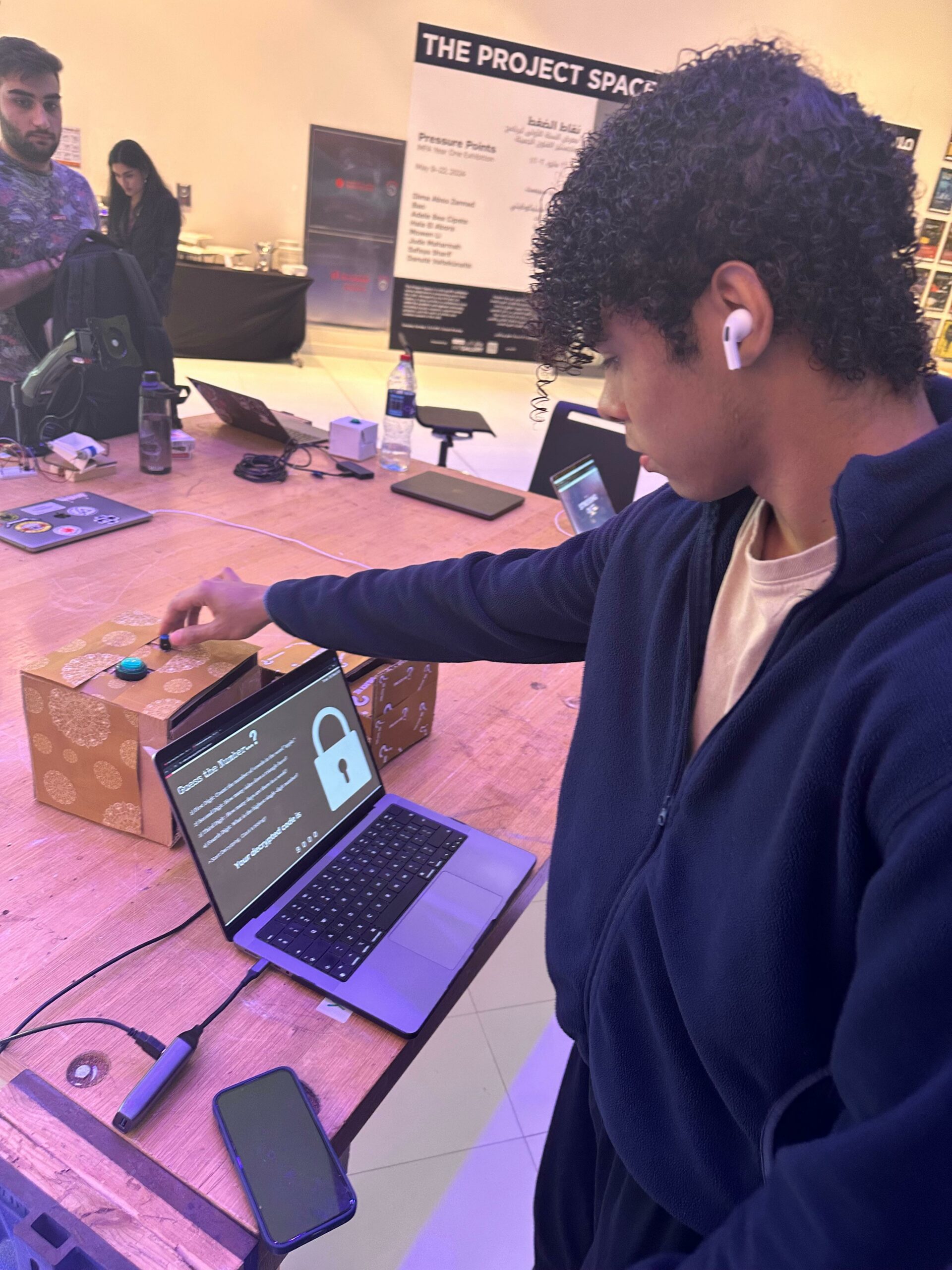
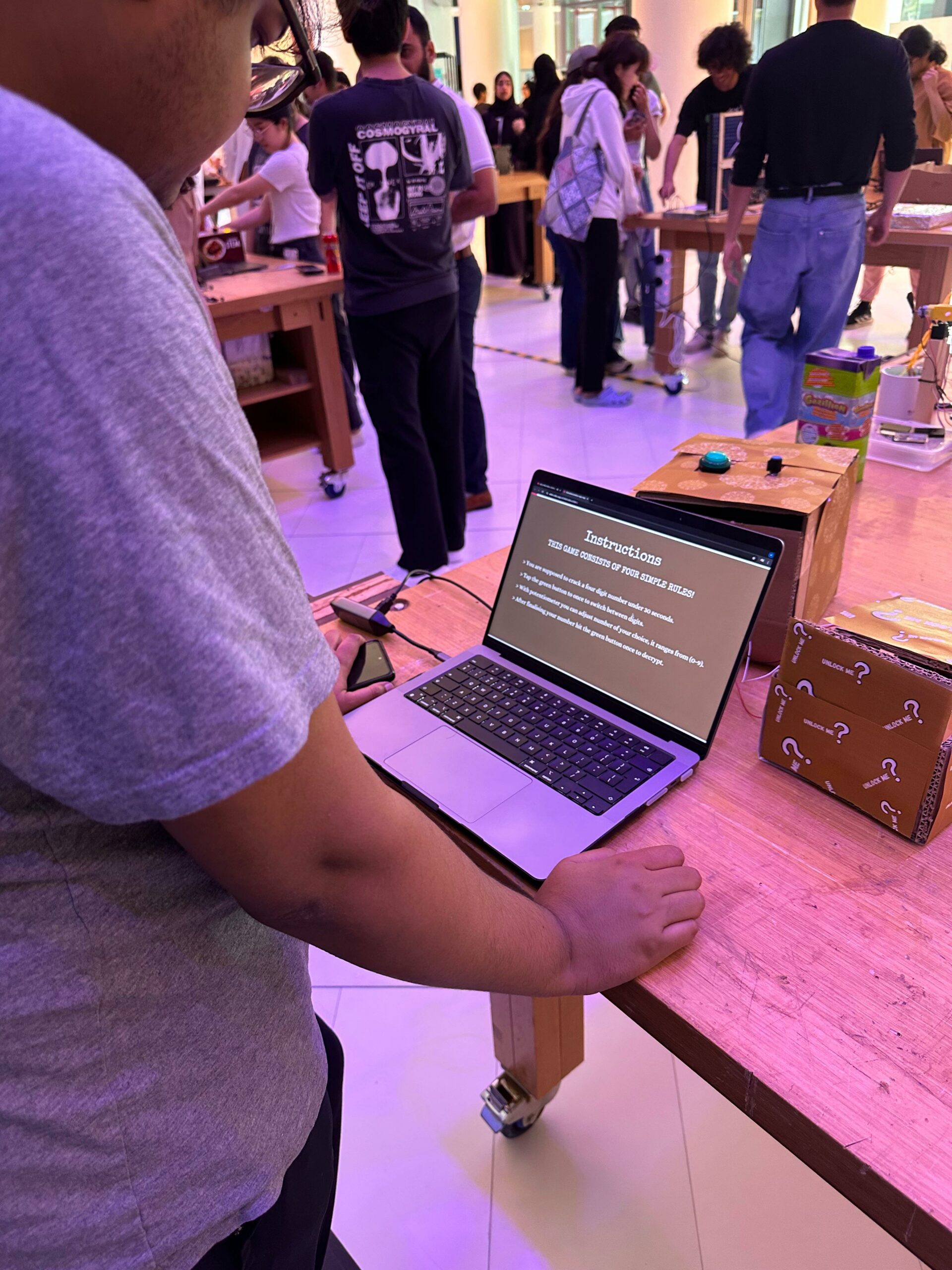
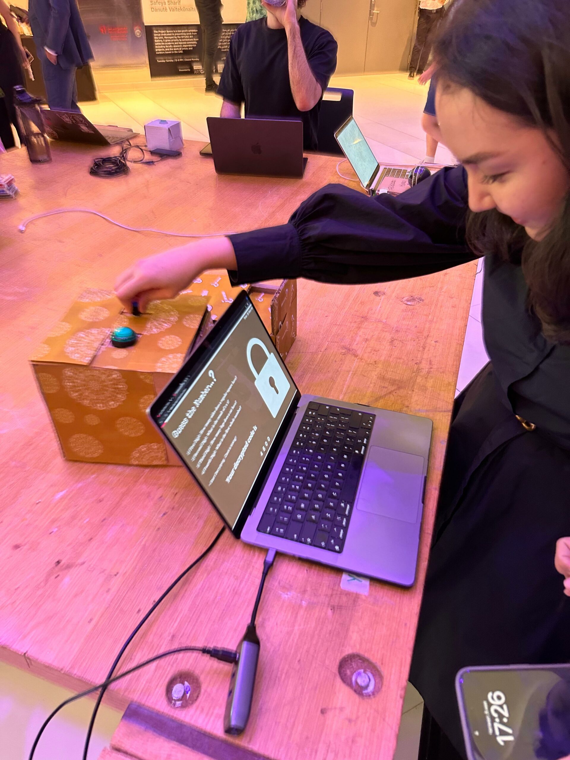
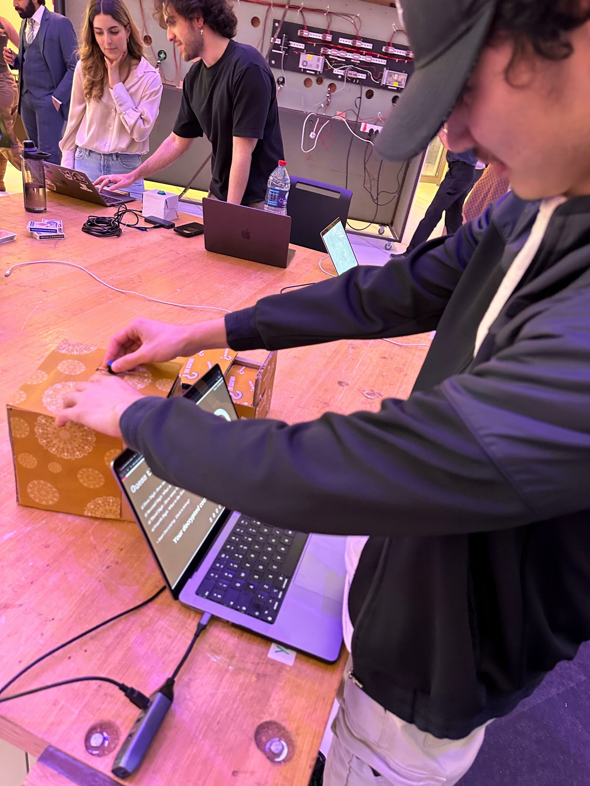
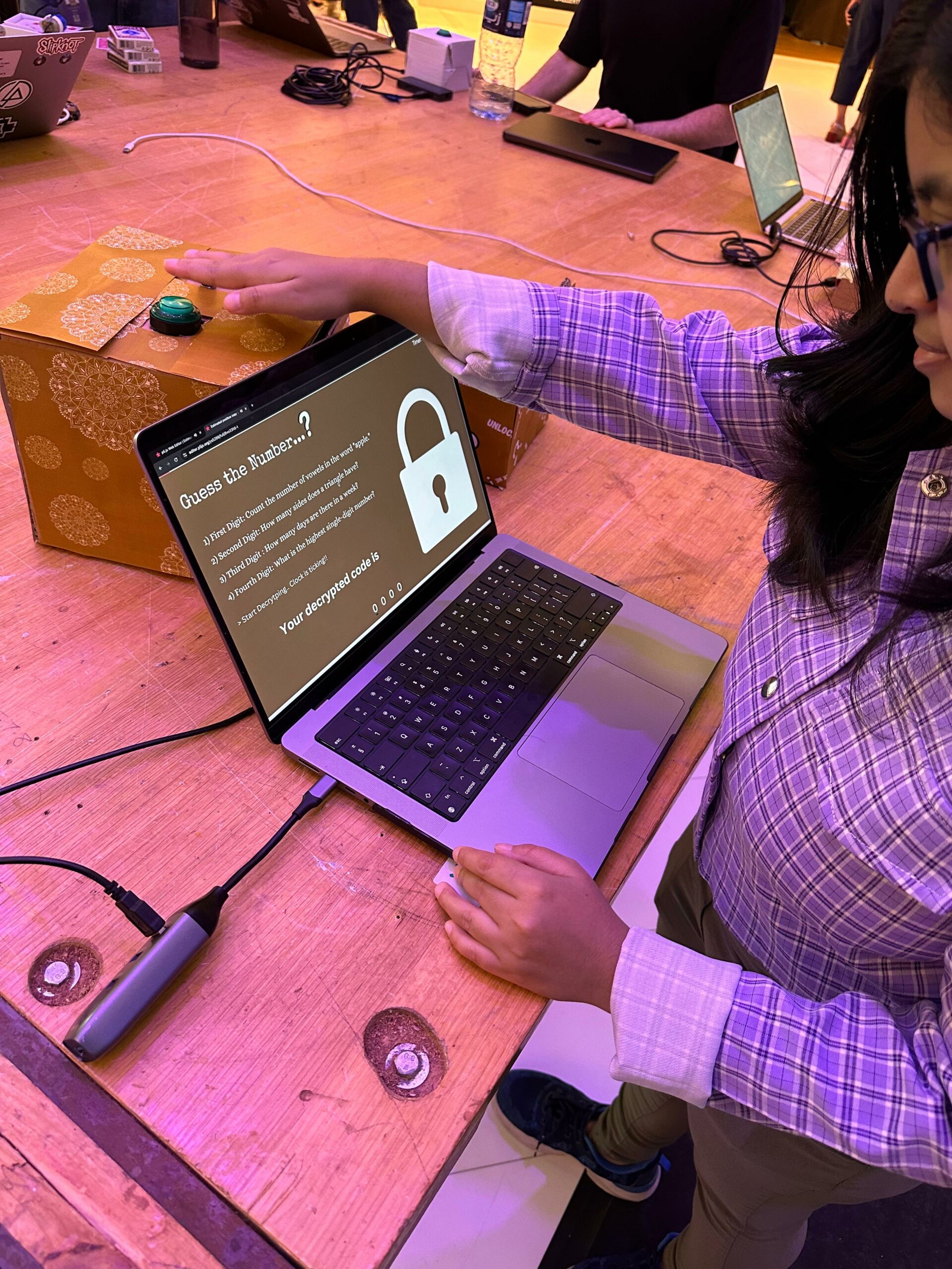
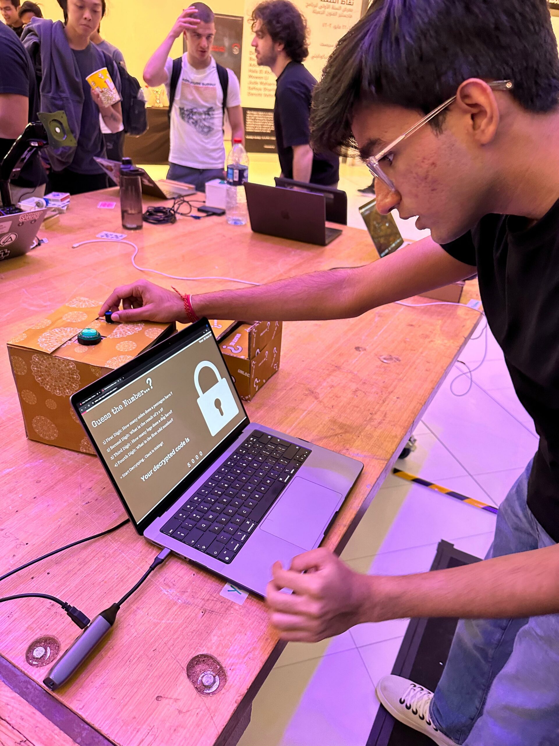
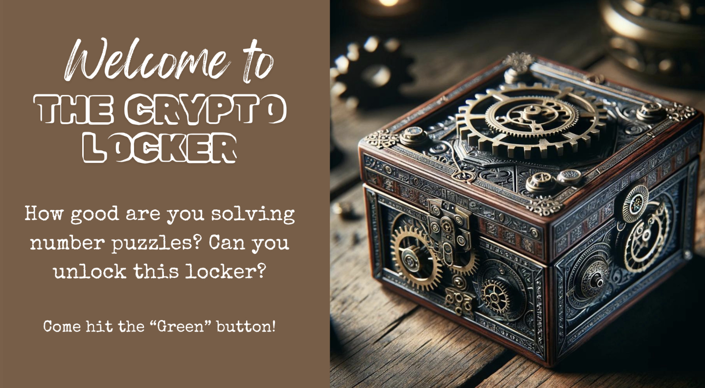
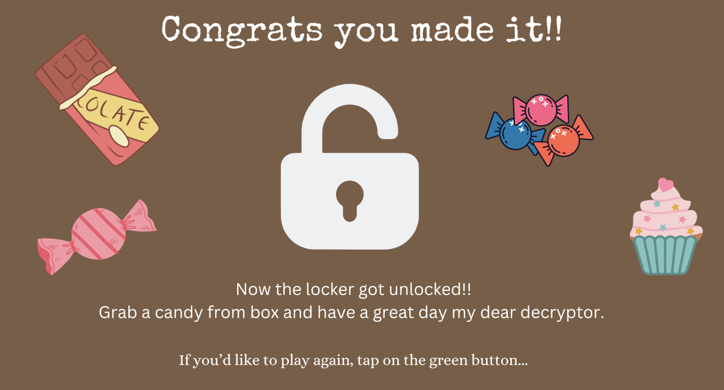
Concept Introduction : The Crypto Locker Puzzle is an interactive project designed to challenge users with a series of numbers-cracking tasks under time constraints. The objective is to solve hints and enter correct codes using a custom-built interface to unlock a cardboard box and win the prize inside. This game combines physical computing with digital elements to create an engaging and educational experience.
1) Dynamic Countdown Timer: A prominently displayed timer adds a sense of urgency and excitement to the gameplay. It counts down from a set time, pushing players to think and act quickly, which enhances the challenge and engagement of the puzzle.
2) Cryptic Hints Display: As players progress, cryptic hints are displayed on the screen to aid in decoding the puzzle. This feature helps to balance the difficulty level and ensures that the puzzle remains solvable while still challenging.
3) Feedback on Input Accuracy: When players enter a code, the interface immediately provides feedback. If the code is incorrect, players are prompted to try again, and if correct, a success message is displayed, and the box unlocks. This immediate feedback loop keeps players engaged and informed.
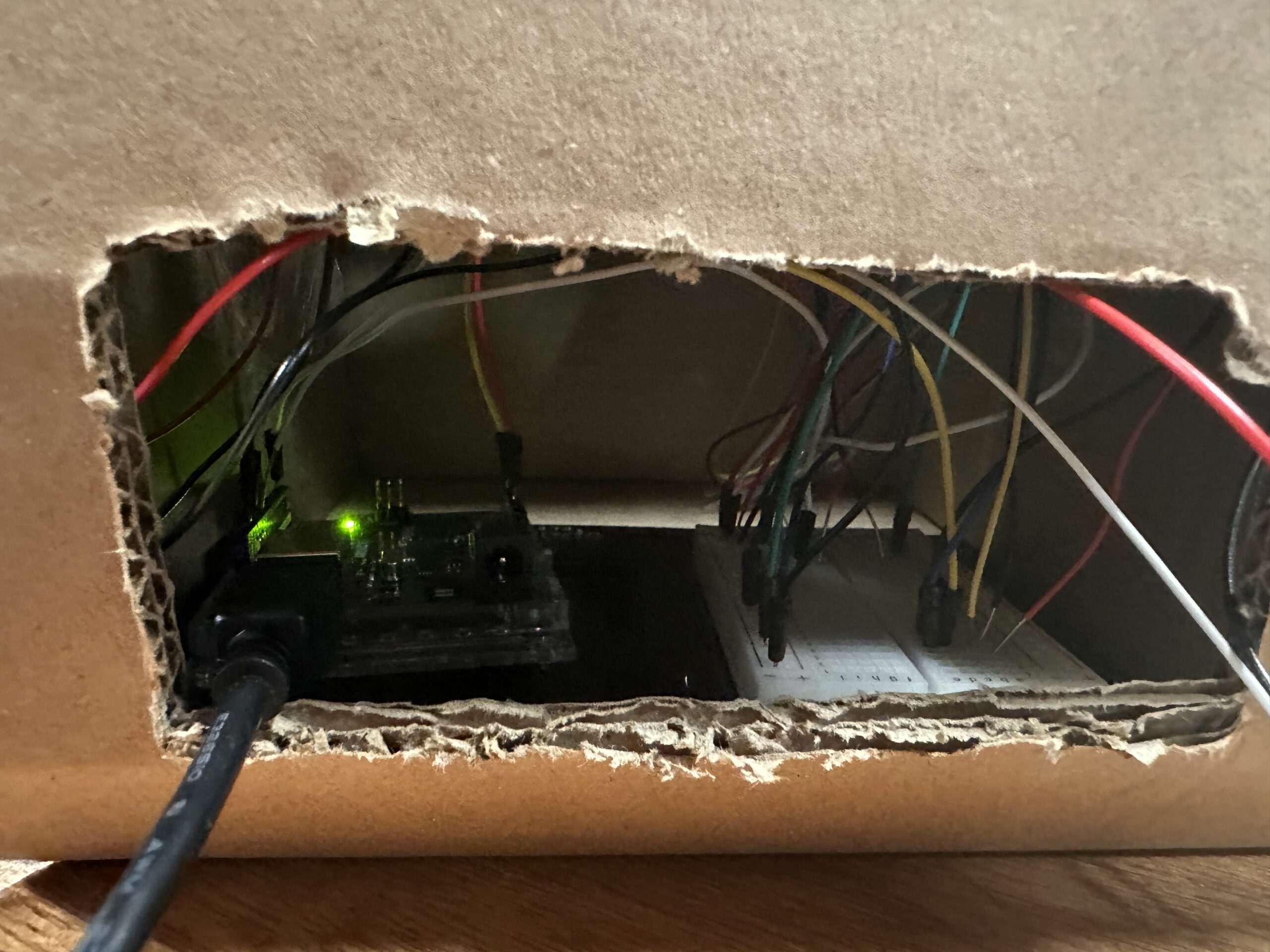
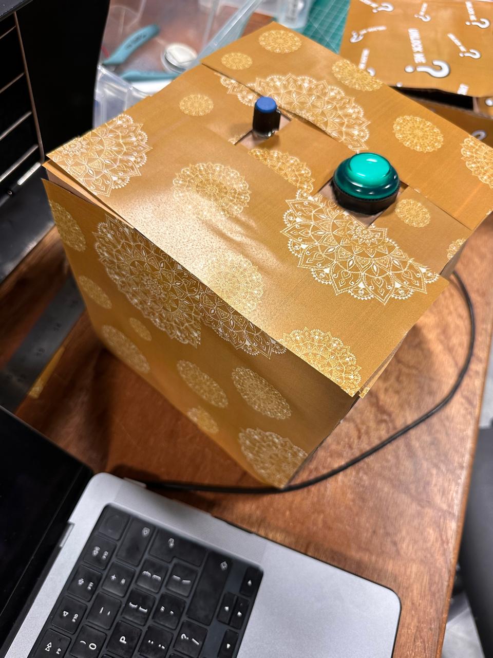
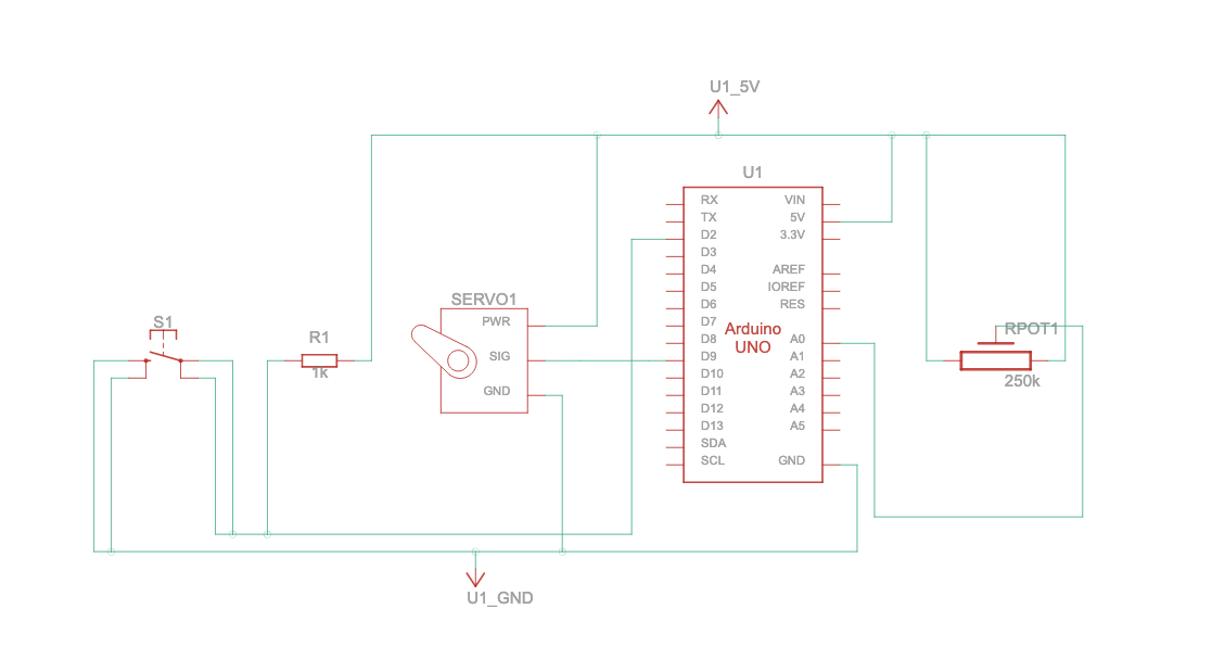
Components I used:
1) Arduino Uno: Serves as the main controller for input and output operations.
2) Servo Motor: Operates the locking mechanism of the box.
3) Potentiometer: Allows users to select digits for the code
4) Button: Used for entering selected digits and navigating through the game.
5) P5.js: It acts like a digital interface that provides instructions, feedback, and manages the timer and attempt counter.
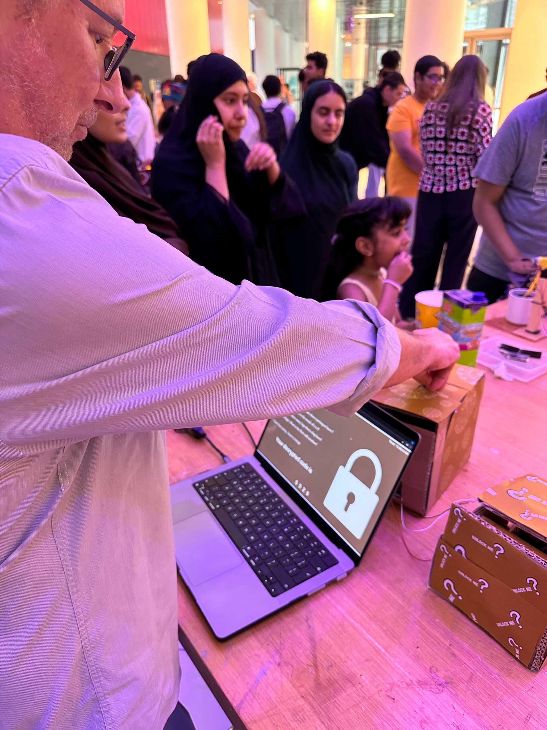
IM ShowPictures: People interacting with my project
What’s the role of P5.js and Aurdino in this project?
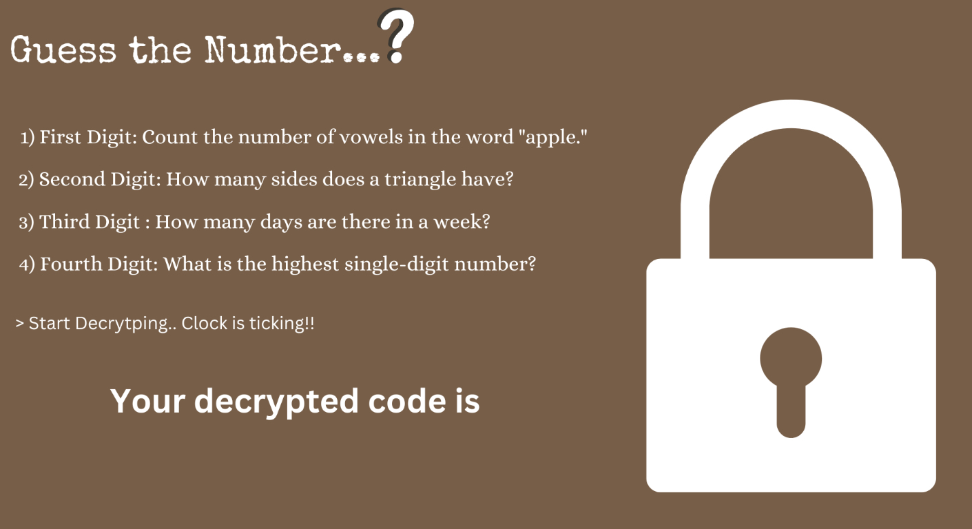
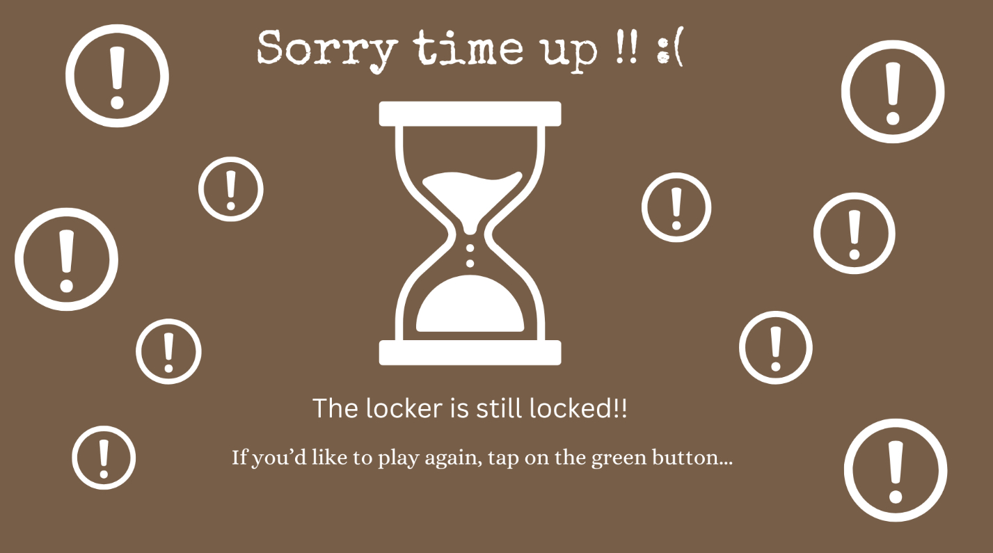
P5.js Sketch: The P5.js sketch handles the game logic and user interface. It displays hints and the countdown timer.
Images:
Arduino Sketch: The Arduino controls the hardware aspects of the project. It uses a servo motor to lock and unlock the box. A potentiometer is used for dialing in digits (0-9), and a button confirms the entry of each digit. The Arduino sends these inputs to the P5.js program, which processes them to determine if the entered code matches the required one.
#include <Servo.h> // Include the Servo library

const int buttonPin = 2; // Push button connected to digital pin 2
int buttonState = 0;     // Variable to store the button state
const int potPin = A0;   // Potentiometer connected to analog pin A0
Servo servoMotor;        // Create a servo motor object

void setup() {
  pinMode(buttonPin, INPUT); // Set button pin as input
  Serial.begin(9600);        // Initialize serial communication
  servoMotor.attach(9);      // Attach the servo motor to digital pin 9
  servoMotor.write(0);       // Set initial position of the servo motor to 0 degrees
}

void loop() {
  buttonState = digitalRead(buttonPin); // Read the state of the button

  // If the button is pressed (buttonState is LOW)
  if (buttonState == LOW) {
    Serial.println("Button pressed!"); // Send message to serial monitor
    delay(1000); // Delay to debounce the button
  }

  // Read the value from the potentiometer and send it to the serial port
  int potValue = analogRead(potPin); // Read the value from the potentiometer
  int mappedValue = map(potValue, 0, 1023, 0, 10); // Map the value to the range 0-9
  Serial.println(mappedValue); // Send the mapped value to the serial port

  // Check if a signal is received from p5.js to control the servo motor
  while (Serial.available() > 0) {
    int signal = Serial.read(); // Read the signal from serial port
    if (signal == '0') { // Signal to reset servo motor to 0 degrees
      servoMotor.write(5); // Turn the servo motor to 0 degrees
    } else if (signal == '1') { // Signal to turn servo motor to 90 degrees
      servoMotor.write(90); // Turn the servo motor to 90 degrees
    }
  }

  delay(100); // Delay for stability
}
How the communication between P5.js and Aurdino Worked??
Initially I prepared the Arduino sketch to transmit data over the serial port. I wrote code to read sensor inputs, such as button presses or potentiometer values, and sent this data as messages over the serial port using functions like Serial.println() or Serial.write(). In my P5.js sketch, I initialized a serial port object within the setup() function using the new p5.SerialPort() constructor. This object represented the communication channel between my P5.js sketch and the Arduino connected to my computer.
Later I configured the serial port to listen for incoming data by using the serial.on('data', serialEvent) function. This setup ensured that whenever data was received on the serial port, the serialEvent function was automatically called, allowing my P5.js sketch to react to data sent from the Arduino. Within the serialEvent function of my P5.js sketch, I read incoming data from the serial port using the serial.readLine() function. This function retrieved a line of text sent from the Arduino over the serial port. I then processed this data based on its content, performing actions such as updating the display or triggering events in my P5.js sketch.
Additionally, I enabled bidirectional communication by allowing my P5.js sketch to send data back to the Arduino. This allowed me to control actuators connected to the Arduino, such as servo motors or LEDs, from my P5.js sketch. I used the serial.write() function to send data from my P5.js sketch to the Arduino and vice-versa, facilitating interactive control over hardware components.
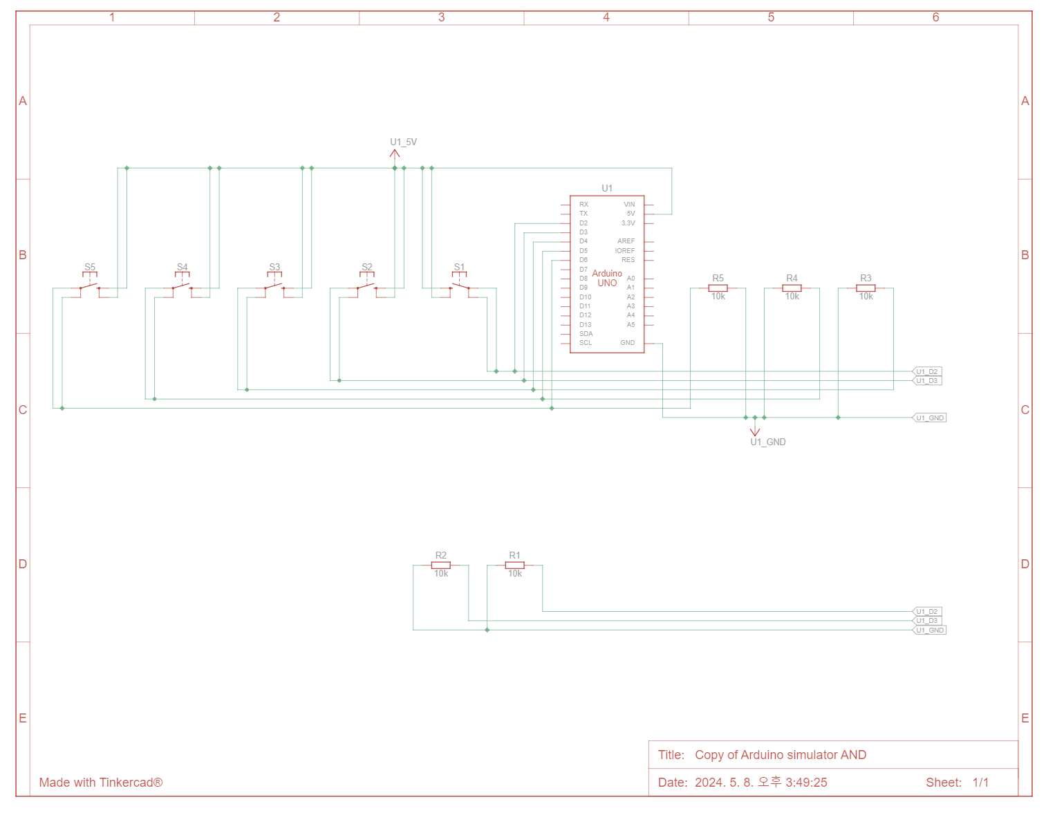
Schematics of the complete circuit:
How the initial game works:
Challenges and Code I’m Particularly Proud of:
Among various aspects of my project, there’s one particular area that stands out – the locking mechanism.
Initially, the locking mechanism was designed to activate when the user entered all the codes correctly within a specific time frame. Subsequently, P5.js was supposed to send a signal to Arduino instructing it to rotate the servo motor to 90 degrees. However, I encountered challenges in implementing this functionality. Despite extensive debugging efforts, I struggled to achieve the desired outcome. It took numerous tutorial videos and multiple attempts, but eventually, I successfully resolved the issue.
// Check if the final number matches the correct code
  if (finalNumber === currentNumCode) {
    currentImage = congratsImg; // Display 'congrats.png'
    // Stop all other sounds and play win
    stopAllSounds();
    winSound.play();
    // Send signal to turn servo motor to 90 degrees
    serial.write('1');
  } else {
    currentImage = wrongImg; // Display 'wrong.png'
    // Stop all other sounds and play error
    stopAllSounds();
    errorSound.play();
  }

  // Reset values for the next round
  dashValues = [0, 0, 0, 0];
  currentDashIndex = 0;
  allowNumberSelection = false;
  clearInterval(timerInterval); // Stop the timer
}
Following the adjustment, I found that relying solely on correct numerical input wasn’t effective. Instead, I implemented a solution where upon displaying the “congrats.png” image in P5.js, the servo motor rotates 90 degrees, indicated by the code serial.write('1');. Conversely, if the “congrats.png” image is not displayed, the servo motor remains at 0 degrees, signified by serial.write('0');.
function serialEvent() {
  let message = serial.readLine(); // Read the incoming serial data

  if (message.includes("Button pressed!")) {
    // Toggle between images based on currentImage
    if (currentImage === welcomeImg) {
      serial.write('0');
      currentImage = instImg;
      // Stop all other sounds and play bgm
      stopAllSounds();
      bgmSound.play();
      // Reset the dashes to 0 when returning to welcomeImg
      dashValues = [0, 0, 0, 0];
      currentDashIndex = 0;
      allowNumberSelection = false;
      // Send signal to reset servo motor to 0 degrees

    } else if (currentImage === instImg) {
      allowNumberSelection = true; // Allow number selection
After successfully implementing this functionality, I extended its use beyond just locking mechanisms. I ensured that the system would automatically lock after the user restarted the game, enhancing the overall user experience.
Future Improvements and Comments from Users:
1. As initially planned in the game development, I would like to introduce a concept of levels. This will give players a strong sense of achievement as they complete each level. This is what one of my friend suggested after playing the game after multiple times.
2. To enhance this project even more, I aim to create a compelling story that will engage players deeply in the crypto game and enhance their overall gaming experience. In addition I would also like to add the SFX, for the number selection and opening the box.
3. Finally, I plan to add more locks (servo motors) to the candy box to make it more challenging to open. This will further motivate players to experience the thrill of unlocking the box.
Overall, I would say this has been an incredible opportunity to test my hardware skills. Admittedly, I struggled at the beginning. However, as I delved deeper into the project, things gradually became more interesting. At one point, I even assembled the circuit without consulting any references, which I’m really proud of!
I would like to wholeheartedly thank my friends, professor, and everyone who played the Crypto Locker Game. The excitement people showed when unlocking the box under time constraints made me forget all the challenges I faced during the build. This experience has significantly heightened my interest in physical computing! Looking forward…