
1- Project Concept
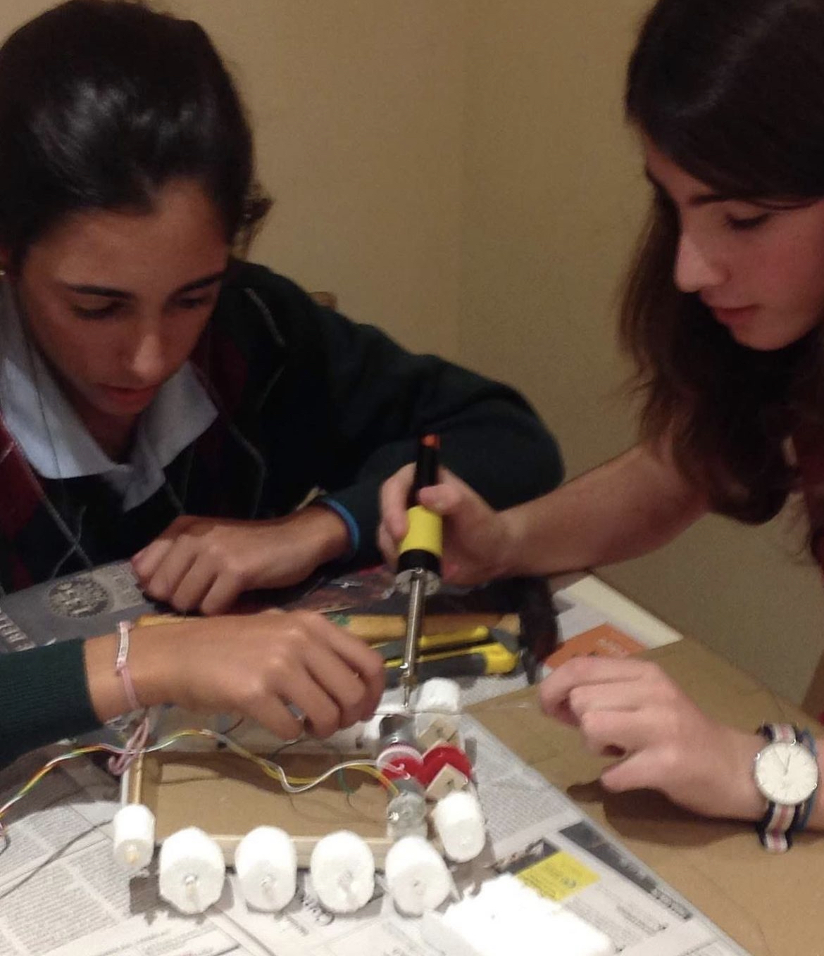
My final project involves designing an automated car that intelligently accesses a parking space. This project is a development of a middle school project I worked on where I made a remote-controlled tank. I’ve now used Arduino to create a self-driving automobile that easily interacts with the P5.js environment thanks to my increased expertise.
2016 Tank: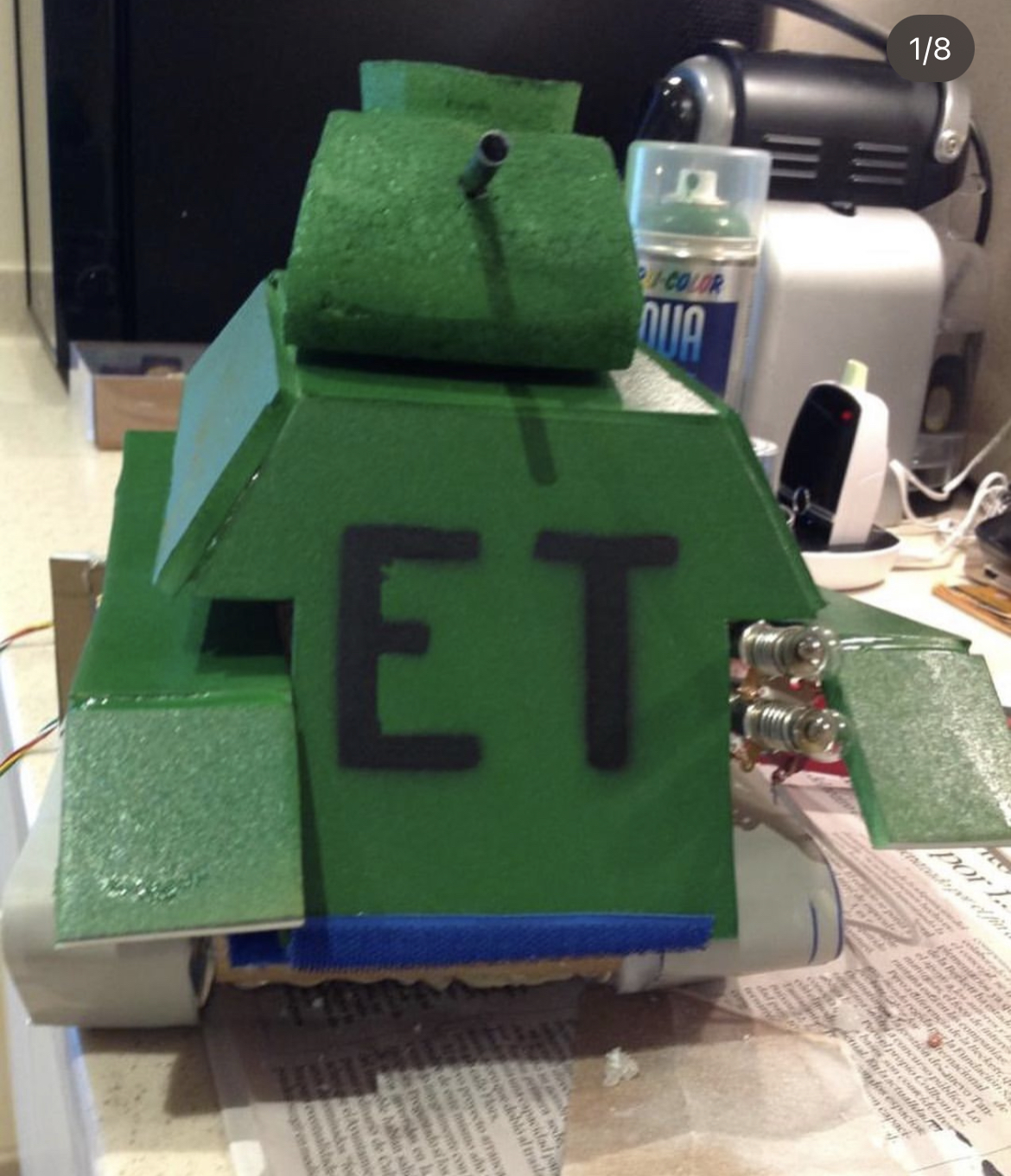
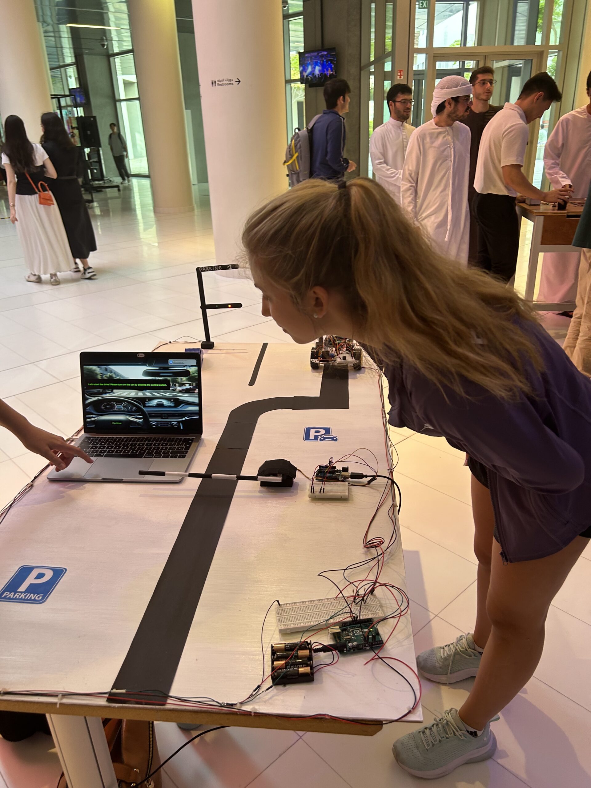
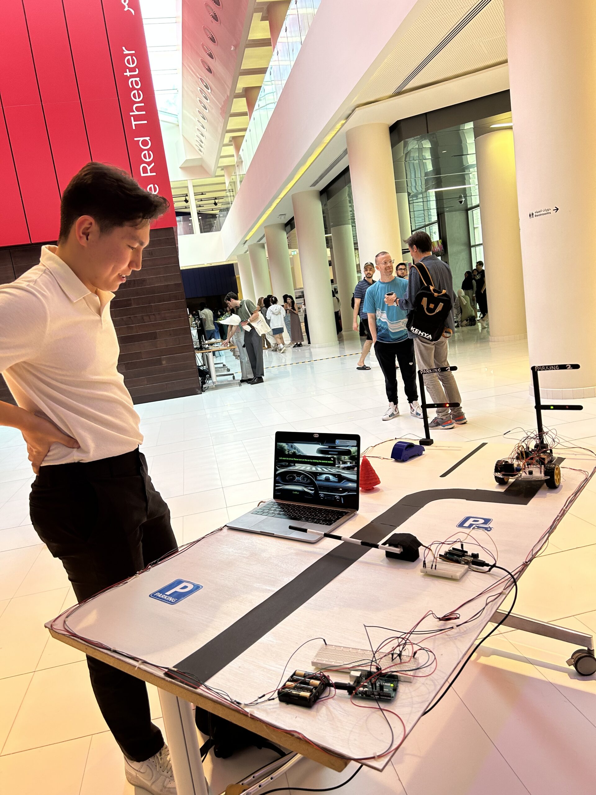
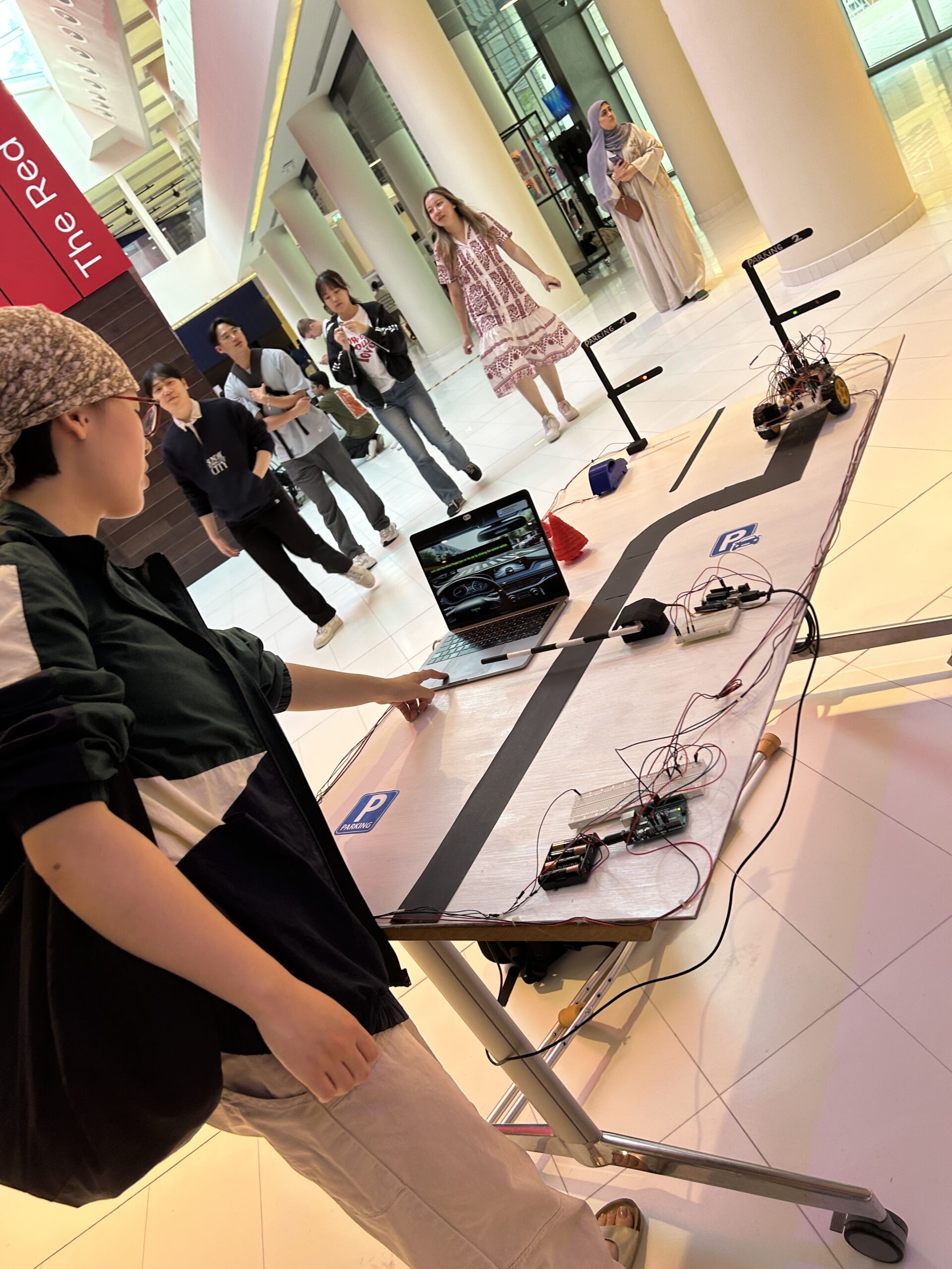
2- Images of the project
link to final project in YouTube: https://www.youtube.com/shorts/cOmEWWDtZFM
https://youtu.be/1EuJl0iAHOQ?si=WrhxC-4yxf5Mujc_
3- User Testing videos
https://www.youtube.com/shorts/SENO-uBmUrs
https://www.youtube.com/shorts/Gj2XIiAjtVc
https://www.youtube.com/shorts/efm2x2616WQ
https://www.youtube.com/shorts/Gj2XIiAjtVc
4- How does the implementation work?
- The user sees in P5 the welcome slide and connects the serial communication from P5 to Arduino.
- The next slide says “Press ‘Continue’ to open the gate!” (The parking gate opens)
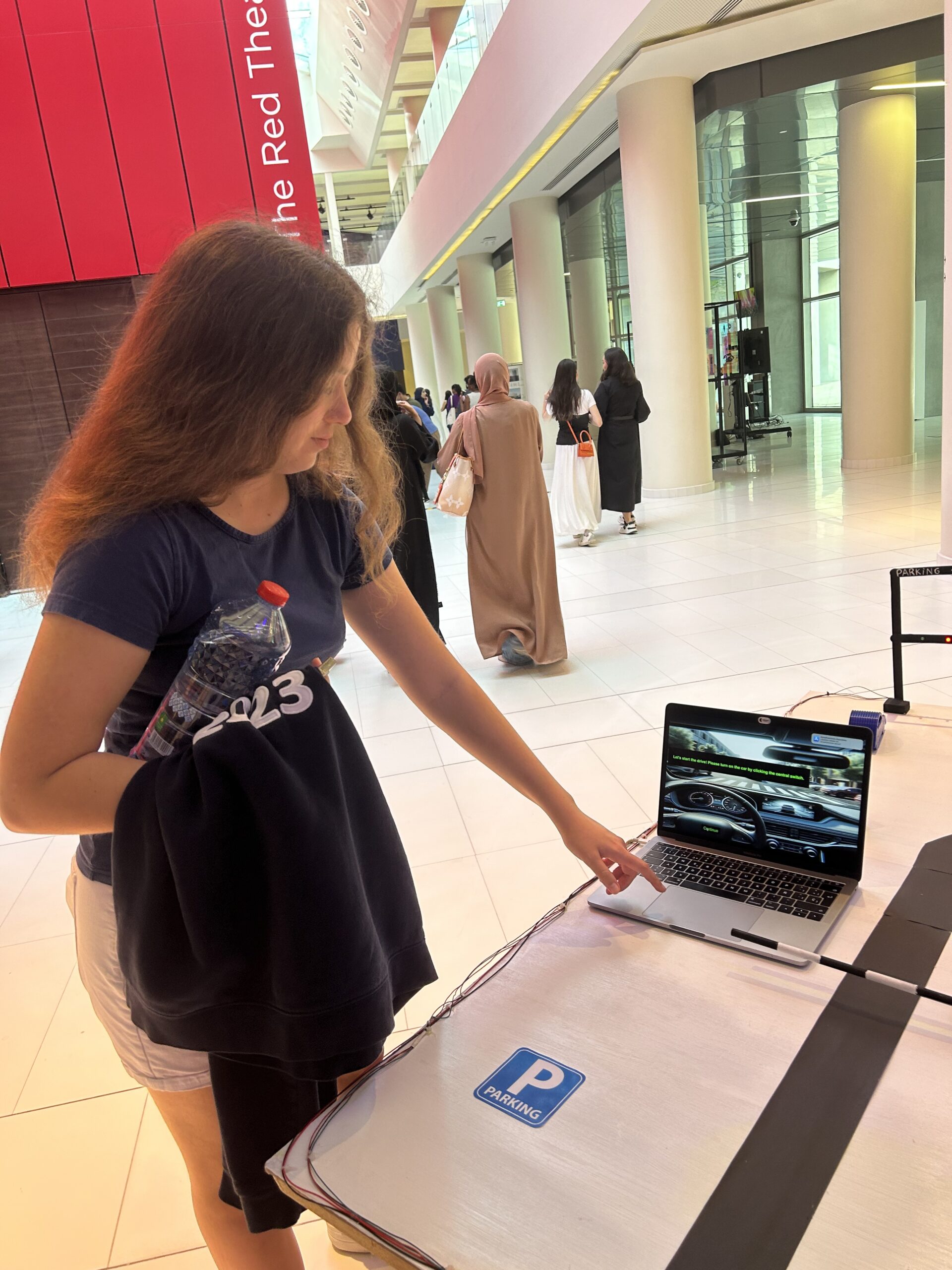
- The next P5 slide says “Let’s start the drive! Please turn on the car by clicking the central switch. (The car will start moving forward)
- the final slide says “Proceed to Parking Spot 2”. (This is because Parking Spot 1 is already occupied by the 3D-printed car)
- Activation and Navigation: The vehicle follows a predetermined black line on the ground when it is activated.
- Parking Completion: The car stops at the end of the black line in front of the Parking 2 sign. At this moment, the traffic light turns from green to red, indicating that the space is now occupied, as the IRS sensor simultaneously measures the vehicle’s weight
4.1- Description of interaction design
4.2- Description of Arduino code + code snippets
Motor code:
void loop() {
 int rightIRSensorValue = digitalRead(IR_SENSOR_RIGHT);
 int leftIRSensorValue = digitalRead(IR_SENSOR_LEFT);


 Serial.print("Right IR Sensor Value: ");
 Serial.println(rightIRSensorValue);
 Serial.print("Left IR Sensor Value: ");
 Serial.println(leftIRSensorValue);


 if (rightIRSensorValue == HIGH && leftIRSensorValue == HIGH) {

   // Both sensors detect black - move forward
   rotateMotor(-MOTOR_SPEED, -MOTOR_SPEED);
   Serial.println("Both sensors detect black - Moving forward");
 } else if (rightIRSensorValue == LOW && leftIRSensorValue == HIGH) {

   // Right sensor detects white, left detects black - turn right
   rotateMotor(-MOTOR_SPEED, 0);
   while (digitalRead(IR_SENSOR_RIGHT) == LOW) {} // Wait until right sensor detects black
   rotateMotor(-MOTOR_SPEED, -MOTOR_SPEED);
   Serial.println("Right sensor detects white - Turning right");
 } else if (rightIRSensorValue == HIGH && leftIRSensorValue == LOW) {

   // Left sensor detects white, right detects black - turn left
   rotateMotor(0, -MOTOR_SPEED);
   while (digitalRead(IR_SENSOR_LEFT) == LOW) {} // Wait until left sensor detects black
   rotateMotor(-MOTOR_SPEED, -MOTOR_SPEED);
   Serial.println("Left sensor detects white - Turning left");
 } else {

   // Both sensors detect white - stop
   rotateMotor(0, 0);
   Serial.println("Both sensors detect white - Stopping");
 }
}


void rotateMotor(int rightMotorSpeed, int leftMotorSpeed) {

 // Set the direction and speed for the right motor
 digitalWrite(rightMotorPin1, rightMotorSpeed < 0 ? LOW : HIGH);
 digitalWrite(rightMotorPin2, rightMotorSpeed < 0 ? HIGH : LOW);


 // Set the direction and speed for the left motor
 digitalWrite(leftMotorPin1, leftMotorSpeed < 0 ? LOW : HIGH);
 digitalWrite(leftMotorPin2, leftMotorSpeed < 0 ? HIGH : LOW);
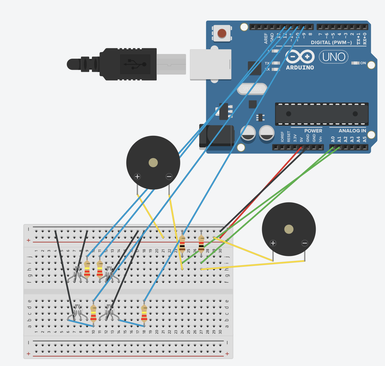
LED+Piezzo:
// LED Pins
const int redLEDPin1 = 12;
const int greenLEDPin1 = 11;
const int redLEDPin2 = 10;
const int greenLEDPin2 = 9;

// Sensor Pins
const int forceSensorPin1 = A0;
const int forceSensorPin2 = A1;

void setup() {
  Serial.begin(9600);

  // Initialize LEDs
  pinMode(redLEDPin1, OUTPUT);
  pinMode(greenLEDPin1, OUTPUT);
  pinMode(redLEDPin2, OUTPUT);
  pinMode(greenLEDPin2, OUTPUT);

  // Initialize Sensors
  pinMode(forceSensorPin1, INPUT);
  pinMode(forceSensorPin2, INPUT);
}

void loop() {
  int sensorValue1 = analogRead(forceSensorPin1);
  int sensorValue2 = analogRead(forceSensorPin2);
  Serial.print("Sensor 1: ");
  Serial.print(sensorValue1);
  Serial.print(" Sensor 2: ");
  Serial.println(sensorValue2);

  // Control for first set of LEDs
  if (sensorValue1 > 90) {
    digitalWrite(redLEDPin1, HIGH);
    digitalWrite(greenLEDPin1, LOW);
  } else {
    digitalWrite(redLEDPin1, LOW);
    digitalWrite(greenLEDPin1, HIGH);
  }

  // Control for second set of LEDs
  if (sensorValue2 > 100) {
    digitalWrite(redLEDPin2, HIGH);
    digitalWrite(greenLEDPin2, LOW);
  } else {
    digitalWrite(redLEDPin2, LOW);
    digitalWrite(greenLEDPin2, HIGH);
  }
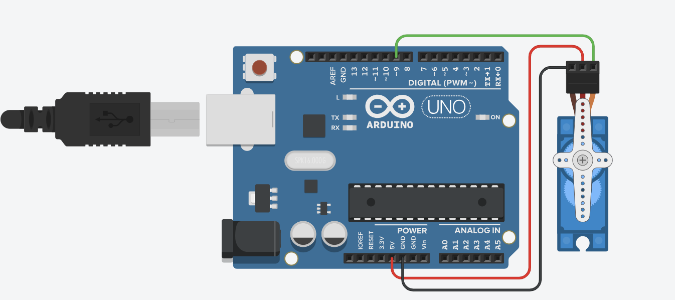
Servo & serial communication:
#include <Servo.h>

Servo myservo;
const int servoPin = 9;

void setup() {
  myservo.attach(servoPin);
  Serial.begin(9600);
  while (!Serial); // Wait for serial port to connect. Needed for native USB port only
  Serial.println("Serial ready"); // Send ready message once serial is set up
  myservo.write(0); // Initialize servo to 0 degrees
}

void loop() {
  if (Serial.available() > 0) {
    String command = Serial.readStringUntil('\n');
    command.trim();
    if (command == "OPEN") {
      rotateServo();
      Serial.println("Gate opened"); // Acknowledge the command execution
    }
  }
}

void rotateServo() {
  myservo.write(90);
  delay(10000);
  myservo.write(0);
}
4.3- Description of p5.js code + code snippets + embedded sketch
https://editor.p5js.org/ec4237/sketches/tGJTp0jqi
function startPresentation() {
  if (!serialActive) {
    // Attempt to set up serial directly in response to the button click
    setUpSerial().then(() => {
      console.log("Serial setup complete, starting presentation.");
      fullscreen(true);
      slideNumber = 0;
      startButton.hide();
    }).catch(error => {
      console.error("Failed to set up serial:", error);
      // Inform the user to retry or check permissions
      alert("Failed to set up serial. Please ensure you allow serial access and try again.");
    });
  } else {
    console.log("Serial already set up, starting presentation.");
    fullscreen(true);
    slideNumber = 0;
    startButton.hide();
  }
}

function getMessage() {
  switch (slideNumber) {
    case 0:
      return "Press 'Continue' to open the gate!";  // Initial message to open the gate
    case 1:
      return "Let's start the drive! Please turn on the car by clicking the central switch.";  // Message to start the car after gate opens
    case 2:
      return "Proceed to Parking Spot 2";  // Final slide message
  }
}

function nextSlide() {
  console.log(`Current slide before increment: ${slideNumber}`);
  if (slideNumber === 0) {
    console.log("Ready to open the gate.");
    sendOpenGateCommand(); // Sends command to open the gate
  } else {
    slideNumber++;  // Increment to move to the next slide for other cases
  }
  console.log(`Moved to slide: ${slideNumber}`);

  if (slideNumber < 2) {
    continueButton.show();
  } else if (slideNumber === 2) {
    continueButton.show();
  } else {
    slideNumber = 0;  // Reset slide number
    continueButton.hide();  // Hide continue button
    console.log("Reset slides and hid continue button.");
  }
}


function sendOpenGateCommand() {
  console.log("Serial already active. Now sending 'OPEN' command.");
  writeSerial('OPEN\n');
  slideNumber++;  // Increment after sending the command
}
4.4- Description of communication between Arduino and p5.js
Arduino and P5 communicate through serial communication when the user clicks to open the gate by pushing a screen button.
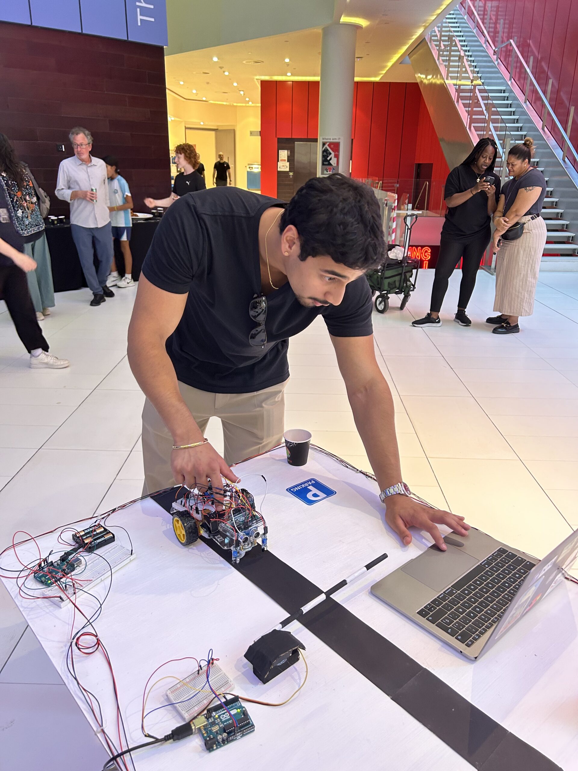
5- What are some aspects of the project that you’re particularly proud of?
- Construction and Configuration: I take particular pride in the construction of the car itself. Mastering its intricate connections was a milestone for me. The process of assembling the car and ensuring all components communicated effectively was a substantial achievement.
- Troubleshooting and Calibration: Another aspect I am particularly proud of is overcoming the challenges with the IR sensors. Calibrating these sensors and fine-tuning the code required persistence and innovation. This effort was crucial in achieving the precise movements I envisioned for the car, allowing it to navigate and respond to the environment as intended.
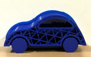
- I really enjoyed printing the 3D model. It was something that I was very curious about and happy to have had this experience.
- It was fun to play around with the Piezzo sensors connecting them to the green and red LEDs
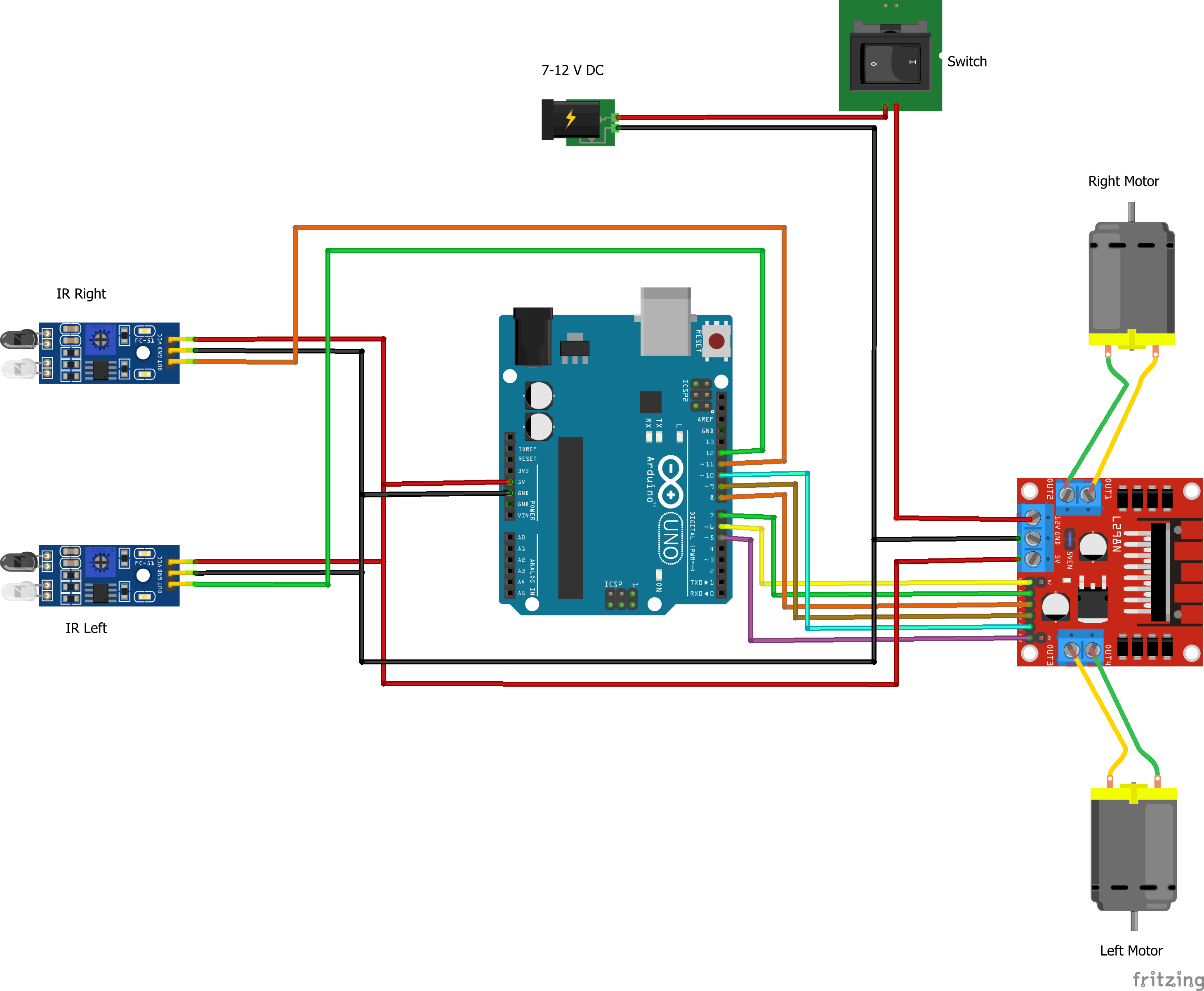
6- Links to resources used
https://github.com/un0038998/LineFollowerRobot/blob/main/Diagrams/LineFollwerRobot.png
https://www.instructables.com/Line-Follower-Robot-Using-Arduino-2/
7- Challenges faced and how you tried to overcome them
Initially, the original plan was that the user placed a car in P1 or P2. The IRS weight sensor would detect the car in the occupied space and send a message in P5 saying that the car should go to the free parking space. Subsequently, the car would go to the unoccupied parking slot. The problem was that I could not figure out the communication between P5 and Arduino. The car got confused when it had to choose whether to go left or right. Therefore, what I did was to have a predetermined route to P1. It is less interactive but I didn’t have the time to investigate a bit deeper. This problem tighs with the next question about future improvements.
Another challenge I faced was the initial connections of the car. I had a problem connecting the switch and the motor shield to the motors.
Additionally, my IRS sensors broke, so I replaced them with piezzo sensors. However, upon connecting the new sensors, I noticed they couldn’t accurately measure the weight of the car because they failed to detect the material of the wheels. Consequently, I sought out another pair of weight sensors capable of identifying the car wheel material.
8- What are some areas for future improvement?
There are a lot of areas that need improvement. 🙂
Starting from the design of the car. I would like to have used the laser cutting machine to make a chassis so that it looked a bit more real.
I envisioned a scenario where the user could select a parking slot, and the car robot would autonomously navigate to the opposite slot. My preference was for the car to navigate without the need for a black line to follow. Initially, I aimed for a fully autonomous vehicle. However, achieving this goal demands additional computational skills beyond my current capabilities.
Originally, I intended to equip the car with an ultrasonic sensor programmed to detect objects and trigger a pause. The concept involved the motors stopping when the ultrasonic sensor detected proximity to an object, prompting the buzzer to emit a two-second beep (similar to cars alerting you of imminent collision). I began coding the buzzer to work in tandem with the ultrasonic sensor, but due to time constraints, I couldn’t complete it. Within the limited timeframe, I struggled to devise a mechanism to temporarily stop the motor upon detection of an obstacle and resume its operation once the obstacle was no longer present.
The weight sensor for the car doesn’t always work. I would have liked to make a bigger area for the sensor to detect it more accurately.
9- IM show documentation, images, videos, and people interacting with your project
Overall, this project is something I am very proud of. I’ve learned so much and I’ve had a lot of fun 😉
Appendix:
Full car code
#include <Arduino.h>


// Define IR sensor pins
#define IR_SENSOR_RIGHT 11
#define IR_SENSOR_LEFT 12


// Define motor speed constant
#define MOTOR_SPEED 180


// Define pins for right motor
int enableRightMotor = 6;
int rightMotorPin1 = 7;
int rightMotorPin2 = 8;


// Define pins for left motor
int enableLeftMotor = 5;
int leftMotorPin1 = 9;
int leftMotorPin2 = 10;


void setup() {
 // Set the PWM frequency for motor control
 TCCR0B = TCCR0B & B11111000 | B00000010;  // Set frequency to 7812.5 Hz
  // Initialize motor control pins
 pinMode(enableRightMotor, OUTPUT);
 pinMode(rightMotorPin1, OUTPUT);
 pinMode(rightMotorPin2, OUTPUT);
  pinMode(enableLeftMotor, OUTPUT);
 pinMode(leftMotorPin1, OUTPUT);
 pinMode(leftMotorPin2, OUTPUT);


 // Initialize IR sensor pins
 pinMode(IR_SENSOR_RIGHT, INPUT);
 pinMode(IR_SENSOR_LEFT, INPUT);
  // Initialize serial communication at 9600 baud for debugging
 Serial.begin(9600);
  // Stop motors initially
 rotateMotor(0, 0);
}


void loop() {
 int rightIRSensorValue = digitalRead(IR_SENSOR_RIGHT);
 int leftIRSensorValue = digitalRead(IR_SENSOR_LEFT);


 Serial.print("Right IR Sensor Value: ");
 Serial.println(rightIRSensorValue);
 Serial.print("Left IR Sensor Value: ");
 Serial.println(leftIRSensorValue);


 if (rightIRSensorValue == HIGH && leftIRSensorValue == HIGH) {

   // Both sensors detect black - move forward
   rotateMotor(-MOTOR_SPEED, -MOTOR_SPEED);
   Serial.println("Both sensors detect black - Moving forward");
 } else if (rightIRSensorValue == LOW && leftIRSensorValue == HIGH) {

   // Right sensor detects white, left detects black - turn right
   rotateMotor(-MOTOR_SPEED, 0);
   while (digitalRead(IR_SENSOR_RIGHT) == LOW) {} // Wait until right sensor detects black
   rotateMotor(-MOTOR_SPEED, -MOTOR_SPEED);
   Serial.println("Right sensor detects white - Turning right");
 } else if (rightIRSensorValue == HIGH && leftIRSensorValue == LOW) {

   // Left sensor detects white, right detects black - turn left
   rotateMotor(0, -MOTOR_SPEED);
   while (digitalRead(IR_SENSOR_LEFT) == LOW) {} // Wait until left sensor detects black
   rotateMotor(-MOTOR_SPEED, -MOTOR_SPEED);
   Serial.println("Left sensor detects white - Turning left");
 } else {

   // Both sensors detect white - stop
   rotateMotor(0, 0);
   Serial.println("Both sensors detect white - Stopping");
 }
}


void rotateMotor(int rightMotorSpeed, int leftMotorSpeed) {

 // Set the direction and speed for the right motor
 digitalWrite(rightMotorPin1, rightMotorSpeed < 0 ? LOW : HIGH);
 digitalWrite(rightMotorPin2, rightMotorSpeed < 0 ? HIGH : LOW);


 // Set the direction and speed for the left motor
 digitalWrite(leftMotorPin1, leftMotorSpeed < 0 ? LOW : HIGH);
 digitalWrite(leftMotorPin2, leftMotorSpeed < 0 ? HIGH : LOW);


 // Apply PWM to the motors
 analogWrite(enableRightMotor, abs(rightMotorSpeed));
 analogWrite(enableLeftMotor, abs(leftMotorSpeed));
}