Week 9 Unusual Switch


For this week’s assignment, we were asked to make an unusual switch without any coding. The inspiration for this came from another project of mine. Back home, I  placed a switch and a simple circuit with an LED panel in my cupboard. A push-button switch is placed in between the hinges of the cupboard. Every time I open the cupboard door, the button gets pushed, and the LED panel lights up, making my life easier.

So, for this, I wanted to think of a simple switch that would make my life easier. I came up with the idea to make a switch that will light up a LED every time I step on it. Imagine waking up at night and taking a step; the LED would promptly light up, guiding your way.

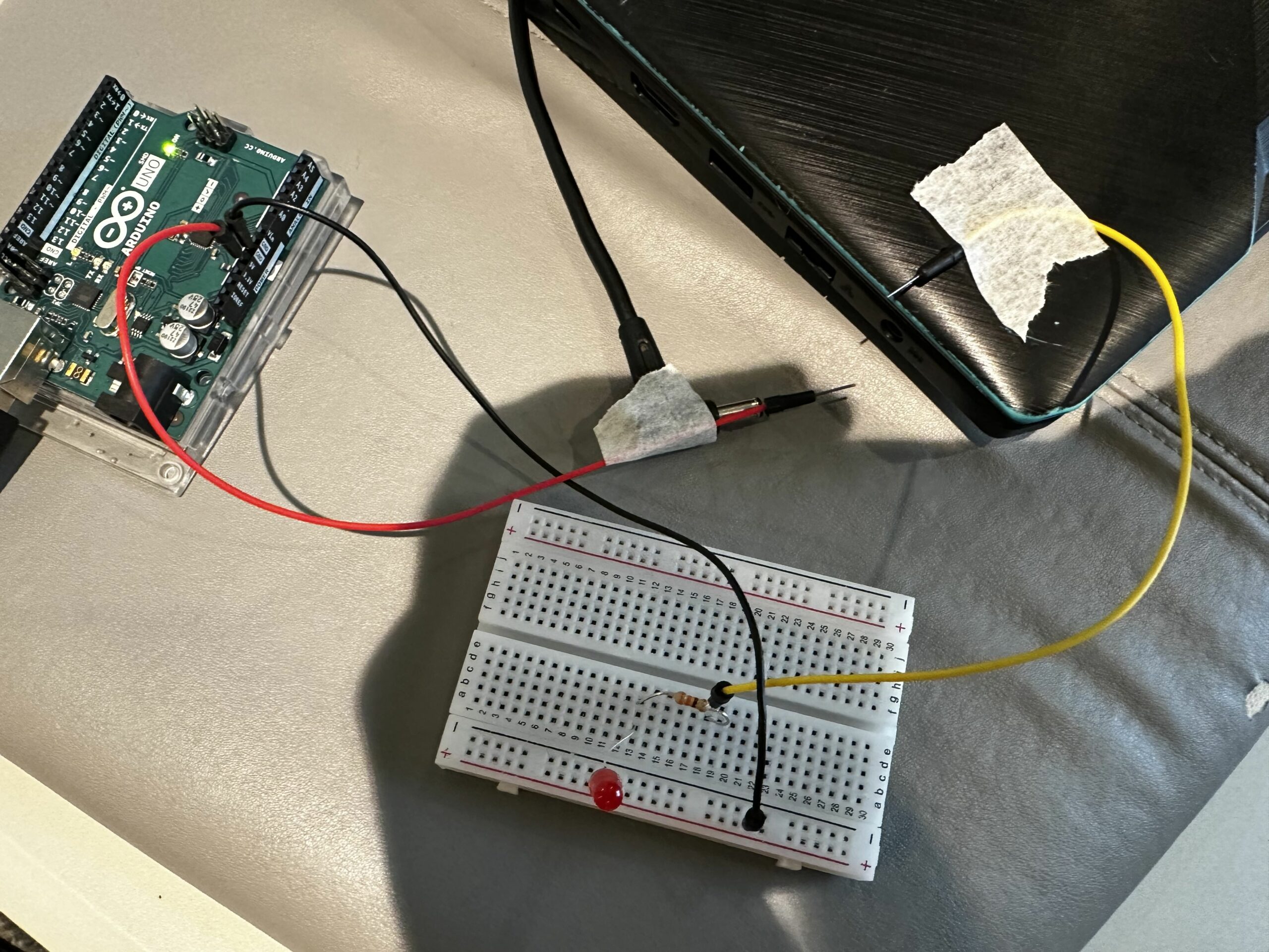
The concept for the switch was to use cardboard from delivery package and copper tape as a switch. Cardboard  will  be  placed  on  the  floor.  And  if there is  pressure  on  the  cardboard  the  LED  will  light  up. 

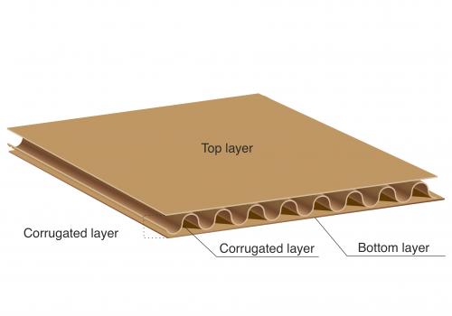
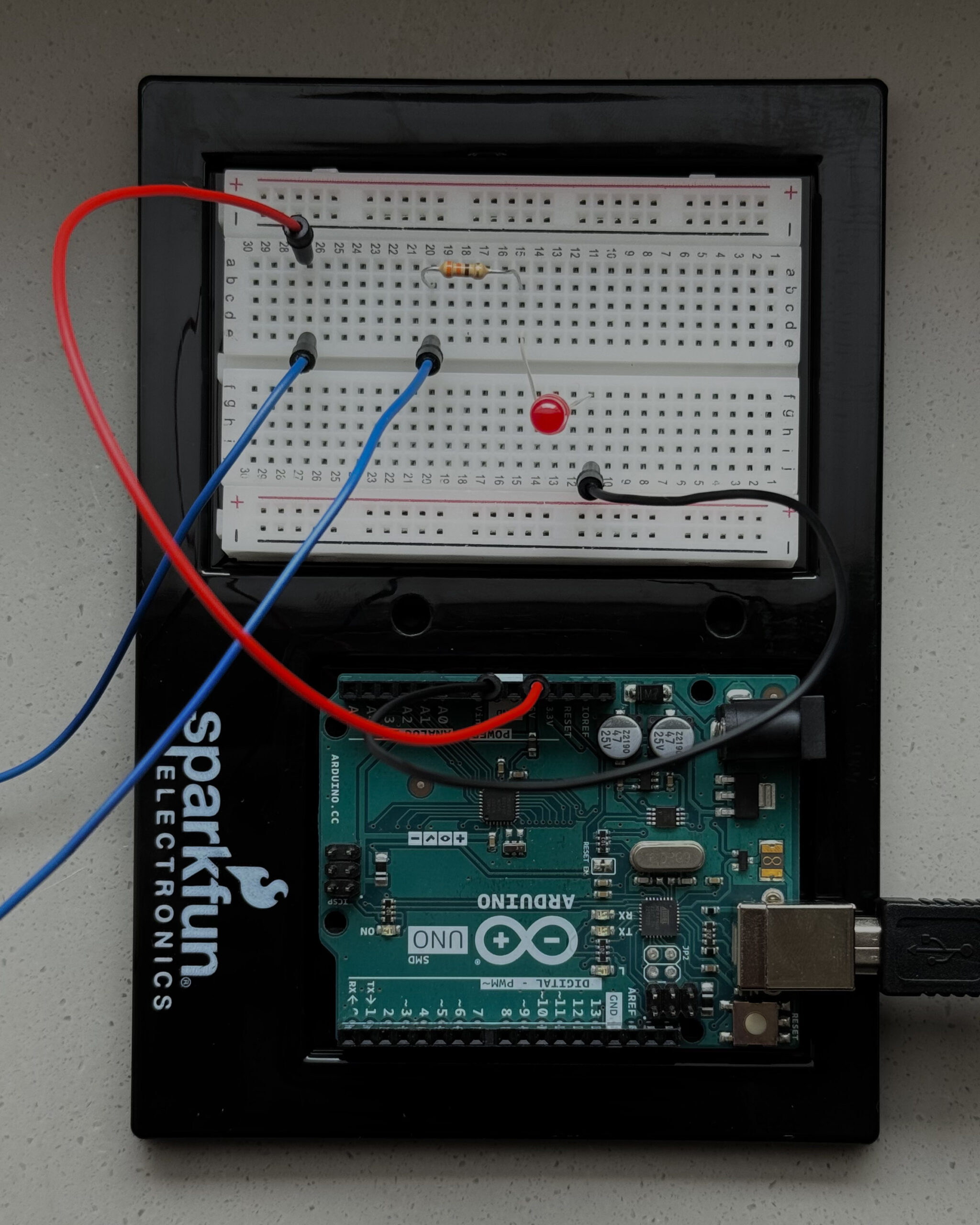
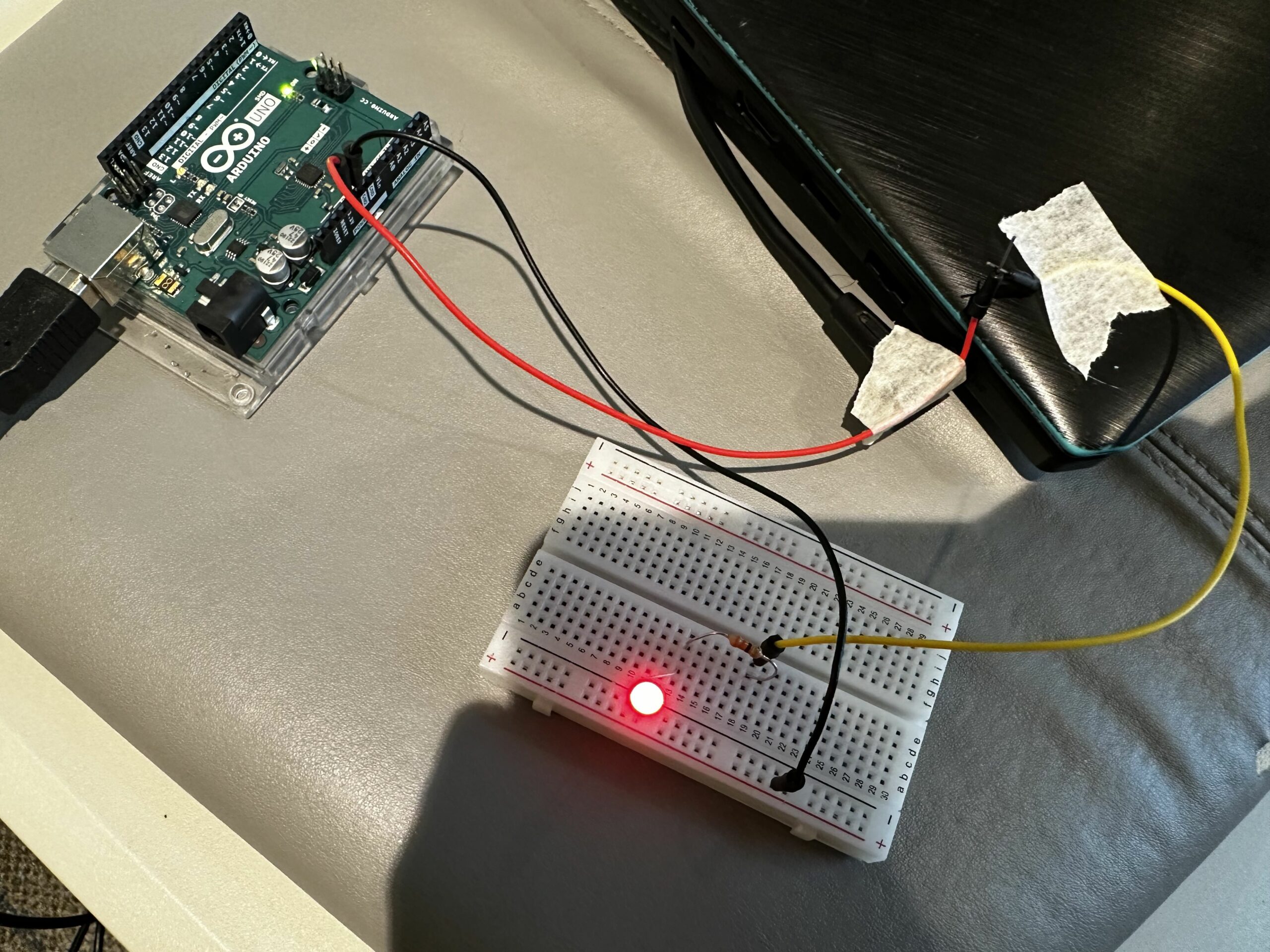
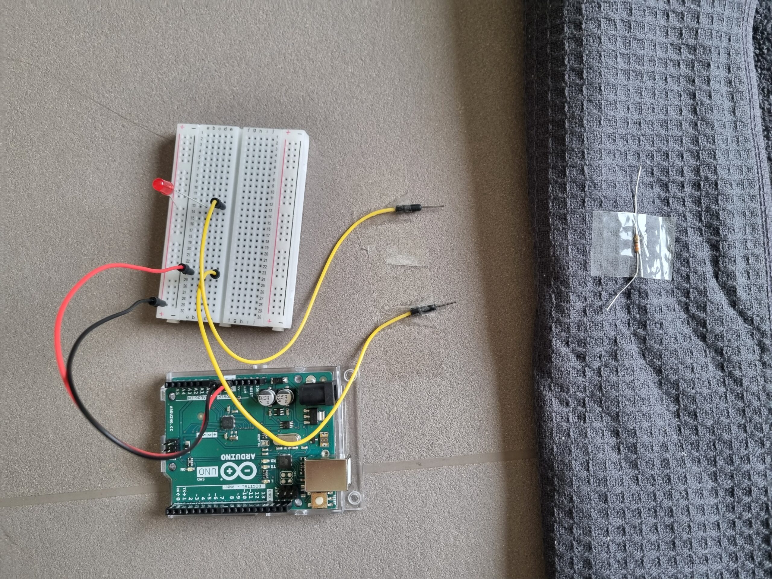
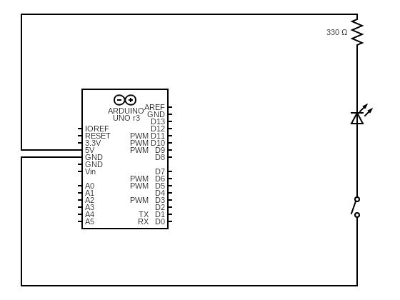
I placed one piece of copper tape on top of the bottom layer and another piece of copper tape under the top layer. So, if there is enough pressure, the in between corrugated layer gets squeezed, and both pieces of copper tape touch each other.  If the pressure gets released, the corrugated layer gets back to its original shape, and the switch disconnects. The copper tapes are connected in between the negative terminal of the LED and the ground of the Arduino. And the positive terminal of the LED is connected to the Arduino’s 5V pin through a 330 ohm resistor.

My Schematic Diagram

The main challenge I faced was deciding on the switch  material itself. I was sure that I wanted to replicate a floor that lights up if you step on it, and as soon as you step away, the LED should turn off, but I could not initially find a material that I could use a switch to replicate this behavior. The other challenging part was cutting the middle layer of the cardboard and placing the copper tapes carefully to avoid unwanted connections. In future, I would want to use any other sensor to detect if someone is stepping on the floor or not and turn on the LED accordingly.

Control LED by light – Week 9

Control LED by light

I created a straightforward project demonstrating a simple light-activated switch using a photoresistor. A photoresistor, also known as a light-dependent resistor (LDR), changes its resistance based on the amount of light it receives. When it’s dark, the resistance is high; when it’s light, it is low.

Components:

  • Arduino Uno
  • Photoresistor
  • Resistor (10 kΩ)
  • LED
  • Resistor (330 Ω)
  • Jumper wires

Setup:

  • Connect one leg of the photoresistor to the 5V pin of the Arduino and the other leg to a digital pin (e.g., pin 2) through a 10 kΩ resistor.
  • Connect the LED to another digital pin (e.g., pin 3) through a 330 Ω resistor.

Upload the following code to your Arduino:

int photo = A0;
int led = 7;

void setup() {
  pinMode(led, OUTPUT);
}

void loop() {
  int lightRaw = analogRead(photo);
  int light = map(lightRaw, 1023, 0, 10, 0);

  if (light < 6) {
    digitalWrite(led, HIGH);
  }

  else {
    digitalWrite(led, LOW);
  }
}

Future Developments

  • One potential future development for this project would be to create a more sophisticated light-activated switch that could be used in various applications. For example, the switch could turn on lights automatically when it gets dark or open and close doors or windows.
  • Another possibility would be integrating the switch into a more extensive system, such as a home automation system. This would allow users to control their lights and other devices with their smartphones or tablets.
  • Additionally, the switch could be made more user-friendly by adding features such as a dimmer switch or a timer. This would allow users to customize the switch’s behavior to suit their needs.
    Overall, this project has many potential future developments. With creativity and ingenuity, the light-activated switch could be used in various ways to make our lives easier and more convenient.I had a lot of fun with this assignment! It was really cool to see how a simple idea could be turned into a daily application that we can use to save electricity.

Week 9 – Unusual Switch

Concept

For this assignment, the task is to create an creative switch that doesn’t require manual activation or coding. Drawing from a personal challenge of frequently and leaving the essential cards like the room and NYUAD access cards in my dorm room, the aim is to design a solution that addresses this issue. The proposed idea is to create a switch that lights up when the wallet is kept in the room and dims when it’s taken out.

Process

So for this project the materials and components used were red LED light, 330 ohm Resistor, 4 Wires, Aluminum foil, tape, Breadboard, and Arduino board. The breadboard circuit connection is shown below:

Video Demonstration

Future Improvements

Sound Effects: I would like to add music or sound effects for a more engaging experience. For example, a pleasant tune could play when the wallet is detected, enhancing user interaction.

Aesthetic Enhancements: I would like to add visual appeal with colorful LEDs or creative casing designs. This will make the device more attractive and blend better with the room decor.

Blinking Lights: I would also like to modify the lights to blink continuously instead of remaining constantly on, which would need some coding integrations.


Week 9: Laptop Charging Switch

Concept: While browsing YouTube for ideas, I noticed that my friend’s old laptop lacks an indicator light for charging. Every time she plugs it in, she’s uncertain if it’s actually charging. So, for my Week 9 project, I’ve decided to help her by using an Arduino to create a simple input/output switch. This will make it easy for her to tell whether her laptop is charging.

Fig 1: This is laptop we will be using for making a switch.


Fig 2: A closer look of connection between laptop and charging cable.

So the ultimate goal of this project is to incorporate an LED that will serve as an indicator when the charging plug is connected to the laptop.

Process: First, I built a basic circuit that uses an Arduino to power a breadboard. I included a red led in the circuit to serve as an indicator of whether the circuit is complete.  So the red wire is supplying power (+5V from the Arduino) to the longer, positive leg of the LED. The shorter, negative leg of the LED is connected to one end of a resistor. The other end of the resistor is connected back to the Arduino board via the black wire, which completes the circuit to GND (ground), allowing the current to flow. When the circuit is closed, a red led turns on. If the circuit is interrupted or there is a break between two wires, then the red led turns off.

Fig 3: An Open or Broken Circuit, The Red Led is in “Off” state.

Fig 4: A Closed Circuit, The LED is in “ON” State.

Components I used:

1) Three jumper wires
2) A Red LED
3)  Arduino
4) A Resistor
5) A USB Cable for connecting Laptop with Arduino
6) A Breadboard
7) A Tape

Video Demonstration:

Link to this video.

Challenges and Future Improvements:

1) Working on this basic circuit board isn’t very challenging for me. However, I find it a bit tricky to attach the wires with tape in such a way that they make a complete connection when the charging cable is plugged in. Getting the angle right for this connection is the challenging part.

2) So for future improvements, I’m considering to use a sensor that can automatically detect whether the cable is connected or disconnected, and do so wirelessly. This would enhance the system’s functionality and user convenience.

Concept:

The concept behind my Unusual Switch project is to transform a regular room door into an innovative electrical switch. This unconventional approach leverages the movement of the door to control the on and off state of an LED light.

Demonstration:

Circuit:

Execution:

I set up a simple circuit with a resistor and an LED. Starting with a ground wire connected to the LED, which then connects to a resistor. To integrate the door into this circuit, I attached one wire wrapped in aluminum foil to the door frame and another, connected to 5V, similarly wrapped and placed on the door. A long strip of aluminum foil on the door’s moving part completes the circuit when the door is closed, lighting up the LED. Open the door, and the circuit breaks, turning off the LED. It’s a neat little setup that turns the action of opening and closing a door into an on-off switch for the light.

Week 9 Creative Switch – “Step”

Concept

There is a moment where imagination sparks innovation. For me, that moment took me back to the muddy adventures of my childhood. Picture this: a young kid, covered in mud, going back home. It is necessary to turn on the lights without adding to the crime scene. And from this muddy dilemma, an idea was born—a switch that doesn’t need a clean hand but just a simple step.

Progress

I made a simple circuit out of these components: 5V – jumper wire – resistor – jumper wire – LED – Ground. It was easy to make the circuit, however, the key was to create a gap in the circuit, hidden beneath the carpet. This gap was placed between the resistor and the jumper wires, completing the circuit only when pressure was applied. Stepping on the carpet would bridge this gap, lighting up the LED. However, this design came with limitations. The switch was only one-time usable. After activation, the gap in the circuit needed manual resetting for the next use.

Reflection

I enjoyed doing this assignment. Of course, the idea that I came up was very simple. However, I could learn from this assignment that creativity comes from everyday problems, and perhaps the solution could be very simple.

Screen Distance Switch | Creative Switches – Week 9

Concept

For this week, we had to make a creative switch. I wanted to use one of the sensors that came along with the Arduino kit to build something simple that could be useful if improved upon later on. I noticed the ultrasonic sensor HC-SR04 that came along with the kit and checked out its documentation to see how it works . Although we weren’t required to use code for this, I realized that all I needed to do to create a switch with this sensor was to install a library and connect it to an input pin . 

Thinking about applications , I recalled reading about the screen distance feature on some mobile phones where users who use their phones at less distance from their face for extended periods of time get a warning .

I set 0-50 cm as the range where the LED light ups to indicate that you are too close to the screen and placed the breadboard and the sensor on my table just above where I usually use my laptop. 

Images 

Video Demonstration

Video link – https://youtu.be/iuf76Mcibu8 

Code

The Arduino code is below : 

#include <NewPing.h> //include the header file 
// Aadil Chasmawala - 31st March 2024
const int LEDPin = 11; // Define LEDPin as a constant integer
NewPing Mysensor(8, 10, 200); // trigger, echo, max_distance = 200cm

void setup() {
  pinMode(LEDPin, OUTPUT); //set LED pin mode to output 
}

void loop() {
  int distance = Mysensor.ping_cm(); //get the distance 
  if(distance > 0 && distance < 50){ //if distance is too close 
    digitalWrite(LEDPin, HIGH); //light up LED
  }
  else{
    digitalWrite(LEDPin, LOW); //switch off LED
  }
  delay(100); //to ensure that the LED doesnt blink too quickly
}

I used a library called NewPing to easily create a NewPing object that can take input from the ultrasonic sensor HC-SR04 . The trigger pin is 8 ,ECHO pin is 10 , max_distance of operation is 200 cm and the LEDPin (for output to the LED ) is 11 . 

This code along with the connections creates the effect of a switch that lights up when one moves close to it , 

Challenges and Reflections 

One of my resistors in the circuit wasn’t working and it took me quite some time to figure out what was wrong  . 

I had initially thought of using a specific sound as a trigger (like a specific song or something simpler like 2 claps  that lights up the LED )  but realized that I would need a sound sensor for this. Hopefully, I will try building something with a sound sensor for one of the assignments as it is very interesting to me . 

In addition , the ultrasonic sensor is very useful too ,  however it operates only in one direction and to accurately get a sense of direction , you would have to use multiple ultrasonic sensors –  something that ?I could explore in future projects .