Final Concept Proposal Confirmation

Final Concept:

I am still going to use ML5 and find a way to implement machine learning with Arduino to develop interactive art project. I did some testing with Canvas painting and while it worked, I found interactive art manipulation to be much more fun and unique. For now I am experimenting with Sin forms and their manipulation with Hand pose. I hope to add new gestures and feature so enhance interactivity of the art. For the Arduino side of things I have not full decided yet but I was thinking of using distance sensor as a tracker for engagement and rest of buttons to change up user interface, colors or perhaps navigate between different mathematical models.


Week 12 – Final Update

My final concept remains the same, although I would like to make it something a bit more. I am considering making it into an allegory for attention by having the sensor control a tracking flashlight. I have yet to figure out how I can attach and control a flashlight in an elegant manner, but that will come with time. Additionally, I have some music playing to enhance the contemplative nature of the piece.

I have begun playing around with methods of attaching the sensor to a servo. Likely, I will attach it to a wheel that was provided with the kit and disguise the wheel with some paper.

I have yet to figure out what exactly I should use the p5 portion for except for music. Initially I wanted a radar-like display but that is no longer suitable for what I want to make. Maybe if I don’t figure out the flashlight problem, I can just have a flashlight or stage graphic on the screen that changes on whether the sensor detects someone or not.

Week 12 Exercises – Tengis & Dachi

Exercise 1

The Arduino continuously reads the electrical signal from a potentiometer. This signal represents the potentiometer’s position based on its rotation. The code then scales this raw sensor reading (ranging from 0 to 1023) to a new range of 0 to 400 using a function called map. This scaled value becomes the control signal for the circle’s movement on the web page.

 The scaled sensor value (now within the 0-400 range) is sent from the Arduino to the p5js code running in the web browser. When data arrives to p5js, the code assigns it to a variable named circleX. This variable essentially controls the circle’s position on the screen. Finally, the code uses this value to dynamically adjust the horizontal position (X coordinate) of the circle drawn on the p5js canvas.

Hardware

  • Arduino Board
  • Potentiometer
  • Computer
  • Wires
  • Breadboard

Picture: 

Video:

https://drive.google.com/drive/folders/1hQqnDHH51cl_E2OkjGjJsFP3ax-MFtd5

Schematics:

Exercise 2

The p5js code continuously tracks the mouse cursor’s position on the canvas (represented by mouseX and mouseY variables). The p5js code directly assigns the mouseX value to the brightness 1 variable and the mouseY value to the brightness2 variable. These variables essentially store the desired brightness levels for the two LEDs. The readSerial function in p5js combines the brightness1 and brightness2 values with a comma (“,”) separator and adds a newline character (“\n”) to create a formatted message. This formatted message is then sent to the Arduino.

Once the data (representing the formatted message) are available, the code reads them using Serial.parseInt. This separates the combined brightness values stored in brightness1 and brightness2. The map function then scales both brightness values from the p5js range (0-400) to the appropriate range (0-255) for controlling the LEDs. The code includes error handling by checking for a newline character (\n) after reading the brightness values. This ensures complete data reception before setting the LED brightness. If no data is received, the Arduino prints an error message “No signal received” to the serial monitor. Finally, the Arduino sets the brightness of each LED (LED 1 on pin 10 and LED 2 on pin 11) based on the corresponding received values (brightness1 and brightness2).

Hardware

    • Computer
    • Arduino Board
  • Two LEDs
  • Connecting Wires

Picture: 

Video: 

https://drive.google.com/drive/folders/1p5D9UuY4ZrFujKK-zVVKQ-zkGdZM75vL

Schematics:

Exercise 3

The p5js code establishes the core mechanics for simulating a bouncing ball on the screen. It defines various physics concepts like: Gravity, Drag, Acceleration and Wind. The code continuously updates the ball’s position and velocity based on the applied forces and drag. When the ball hits the bottom of the canvas, its vertical velocity is reversed, simulating a bounce. At this point, a variable named ledOn is set to 1, indicating the LED should be turned on. If the serial connection is active, the code sends the ledOn value (0 or 1) as a string followed by a newline character (“\n”) to the Arduino using writeSerial.

The readSerial function gets called whenever new data arrives from the Arduino. Here, it parses the received data and assigns it to the windVale variable. This value updates the wind vector, influencing the ball’s horizontal movement in the simulation. The Arduino code continuously reads the analog value from a potentiometer connected to pin A0. It then maps this value (ranging from 0 to 1023) to a new range of -10 to 10 using the map function. This mapped value represents the wind force affecting the ball in the p5js simulation. The Arduino transmits this wind force value to the p5js code. The Arduino constantly checks for incoming data on the serial port. If data is available, it reads the first character and checks its value. If the character is ‘1’, the LED connected to pin 13 is turned on. If the character is ‘0’, the LED is turned off.

Hardware

  • Computer
  • Arduino Board
  • Potentiometer
  • LED
  • Connecting Wires
  • Bread board

Picture: 

Video: 

https://drive.google.com/drive/u/1/folders/1Ro-Iw_UmvcQimw7nk7MeqBhqhtzyy95X

Schematics:

Challenges and Reflection

Overall we faced quite a few challenges, regarding Arduino malfunctioning due to serial communication error. Sometimes it was the fault of code, adapter or p5js. Either way we found step by step troubleshooting to be a solution.  However, in the end we are happy with our progress and this has helped us prepare for our final project.


Week 12 – Reading Response

This week’s reading about design and disability has been eye-opening, prompting a shift in how I perceive both accessibility and aesthetics. It’s clear that the potential of design in creating assistive devices has been vastly underestimated. The notion that functionality must come at the expense of beauty is challenged, as exemplified by everyday items like glasses – seamlessly merging utility and style.

This realization aligns with the idea that good design goes beyond mere usability; it enhances user experience and self-perception. It’s not about creating universally bland solutions, but rather celebrating diversity through targeted designs that cater to individual needs and preferences. Involving artists and fashion designers in this process can inject a sense of identity and personal expression into assistive devices, transforming them from purely functional tools into extensions of oneself.

The shift in language, from “patients” to “wearers” and “hearing aids” to “HearWear,” further emphasizes this transformation. It moves away from medicalized labels and towards empowerment and individuality.

The idea of universal design resonated deeply as well. Creating things everyone can use and enjoy, like the curb cut example, demonstrates how good design benefits a wider range of people than initially intended. It’s not just about accessibility; it’s about smart and inclusive solutions. It’s always important to consider how to get more designers on board with inclusive design and ensure accessibility isn’t an afterthought. This involves asking crucial questions: How can we create a world where everyone feels welcome and valued? How do we ensure diverse needs and aspirations are met, not just accommodated? By merging functionality with individuality and embracing inclusive design principles, we can create a more accessible and empowering world for everyone.

Final Project Proposal

HAILSTORM HAIVOC CONTINUED

Concept for the project

For my final project, I am building on my midterm project, which involves a game where players dodge falling hail. Initially, I had envisioned this game with a car maneuvering to avoid the hail, but the concept became too complex. Through trial and error, I simplified the gameplay to where players now use the mouse click to move the car away from the hail. This feature unexpectedly also allows control over another sprite, adding a unique twist to the gameplay. Taking this project to the next level, I plan to integrate an arcade button to start and re-start the game and a toy car that players can manipulate/move to control the game car on the screen through a sensor. Differing from the midterm which was consistently playing, my game has an end after a couple seconds of playing where the player would have won and arrived home safely from the storm, and this would enhance the interactive experience and depth of the game.

Description of what your Arduino program will do with each input and output and what it will send to and/or receive from P5:

  1. Inputs:
    • HC-SR04 Ultrasonic Sensor: This sensor will measure the distance of an object from it. It uses two pins, TRIG and ECHO, to send out ultrasonic waves and measure the time it takes for the echo to return.
    • Arcade Button: The button will act as a simple digital input, where pressing the button changes its state from LOW to HIGH.
  2. Outputs:
    • Serial Data to P5: The Arduino program will continuously send two pieces of data to the P5 sketch via the serial port:
      • Distance measured by the ultrasonic sensor, translated into a value that indicates the position of the car on the screen, hopefully when the toy car is moved left (close to the sensor it will move the car on screen left) and vise versa.
      • The state of the arcade button to control game states (start and restart).

Description of what P5 program will do and what it will send to and/or receive from Arduino:

As of my game, I don’t think P5 is going to send anything to Arduino other than:  Serial Data from Arduino: The P5 sketch receives the distance and button state as a serialized string. Game Controls: Based on the received data, the P5 sketch adjusts the position of the car on the screen and manages the game state (starting and restarting).

Final Final Project Proposal – Week 12

Safe Russian Roulette

Introduction

After having done a bit more research and some more ideation I am now sure of what I am going to create exactly. Of course there may be some changes down the road but the project should be at least 90% like what I’m going to outline here.

Inspiration

I originally had this idea before the midterm and it was going to be my midterm project but instead I changed it to the Mexican Standoff game. But, what I really wanted to do for both of these projects is make a game or anything that was interactive but that allowed for at least two people to enjoy the experience together.

I had been inspired by the indie game Buckshot Roulette as well. It’s a game where the player plays against a strange looking dealer who has lives and so does the player and the lives are represented by lightning bolts and there are abilities as well which makes the game more tactical. I wanted to almost recreate the game or at least the aesthetic but for now I will not do the abilities since I need to at least finish the foundation, i.e. just normal Russian Roulette.

The lightning bolts representing the lives of both the dealer and the player were done because each of them could be revived with a defibrillator. It was the lightning bolts themselves which lead to me having the idea of a player receiving an electric shock.

Then having the lives and a little menu on the side of the table inspired me to have a p5js sketch which can has a similar aesthetic.

How Russian Roulette works
& How this game will work

In the real game of Russian Roulette a revolver would be loaded with one live round and then the rest would either be empty or blanks.

In Safe Russian Roulette there will also be at least one live “round” and the rest are blanks, totaling 6 rounds. Depending on the difficulty chosen there will be between 1-5 rounds that are live. The names of the difficulties in ascending order are Standard (1 live round), Hard (1-2 live round), Harder (1-3 live rounds), Nearly Impossible (2-4 live rounds), Masochist (3-5 live rounds)

There will be 2 buttons for each player to press to either shoot themselves or the other. When the player shoots themselves they may either shock themselves or it may be a blank. If its a live round they lose and if its a blank they get a second turn which means its more likely that the next round will be live and therefore more likely that they will win if they shoot the other player. Each player has one life. Basically its a game of chance.

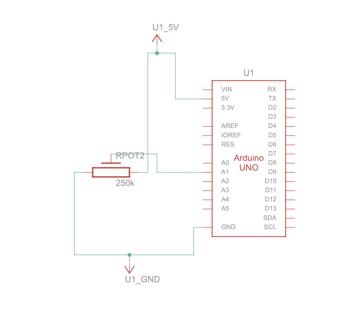
Before the players start shocking each other they will be greeted with a start page. There will be a potentiometer or knob of some kind and a button and together the user can select different options that are displayed using p5js. Options such as difficulty and retry.

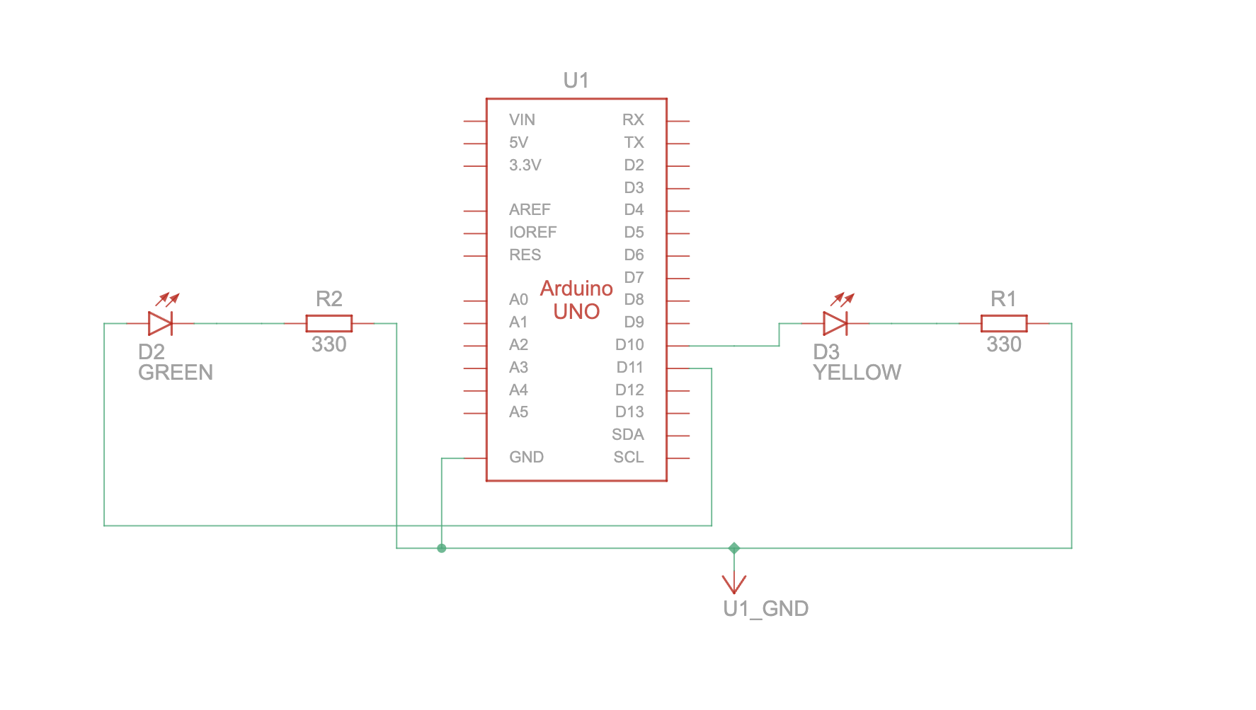
There will also be some kind of lights that flash in a certain way which are in the middle of the table. It will display the number of live and blank rounds at the beginning (it can change color, red = live, white = blank) then, depending on the difficulty, it will either disappear completely, or it will show the number of rounds remaining but it will never show the number of live or blank rounds left, just the number of rounds left at most.

Then after one of the players lose it will indicate on the play screen who won and who lost and then ask the players if they want to play again or not. Also, during the game while the players are playing it will indicate the difficulty that the players are playing at so that others can see and in case they forgot.

Redha Final Project Update – “Selfies for Two <3"

Upon developing the concept for my final project, I have decided to incorporate a more communal element into my work as a means to utilise internet culture to physically bring people together and create tangible memories.

I will be using the same image classification process as described in my initial post but will create my own machine learning model using Google’s Teachable Machine. Doing this will enable the object classification to be more accurate and specific, ensuring a smoother interaction between users and the project. When gathering the sample images for this, I will make sure that the environment and framing is as close as possible to what the program will see on-site in order to ensure its accuracy while being open to the public.

In terms of the communal aspect, the project will require two phones (and therefore two people) to be detected by the program in order to generate the digital mirror. In making this choice, I hope to utilise the tendency we have to take photographs of ourselves as a means to bring us closer with our friends and loved ones, thus replacing an otherwise self-centred process with one that focuses on interpersonal connection. In order to compliment and emphasise this point, I will generating an ASCII-style digital mirror which fills the thresholded space with the text-heart emoticon ‘<3’. Not only does this link to the theme of interpersonal connection, it also refers back to the theme of internet culture which was ultimately the influence behind my project.


Raya Tabassum: Reading Response 7

“Design Meets Disability” provides a rich examination of how design intersects with disability, with a focus on both the historical context and contemporary innovations in the field. It delves into specific examples like eyewear, hearing aids, and prosthetics, and underscores a cultural shift from viewing these items merely as medical aids to considering them as fashion statements and expressions of personal identity.

As someone interested in design, I find the intersection of fashion and functionality particularly fascinating. The way eyewear evolved from a stigmatized medical device to a stylish accessory exemplifies how cultural perceptions of disability and assistive devices can shift dramatically. This shift challenges us to think about other devices in the same light. Could hearing aids or prosthetics become similarly fashionable? This idea encourages a reconsideration of what we define as “normal” and pushes the boundaries of inclusivity in design. From my perspective, embracing design innovation in disability aids not only enhances functionality but also boosts the self-esteem of users. If more designers viewed these aids as opportunities for creative expression, we might see a broader acceptance and desire for these products, much like what happened with eyeglasses.

Week 12 : Pi Final Project Progress

As for the progress on my final project this week, the body frame is already built. I am still assembling the legs (They take time).

Also, in terms of the electronics, I need to order an additional Li-Po battery and a voltage converter to supply the power to the servo motors.

Also, for the cardboard castle above the walker, I began generating the textures in Midjourney. Still in the progress of assembling.

I unfortunately lost my ESP32 chip, so need to re-order it again.

Raya Tabassum: Final Project Concept & Progress

Finalized Concept for the Project:
“Interactive Musical Garden” is an immersive installation combining technology and nature, designed to create a harmonious interaction between physical and digital realms. The project features a set of 3D-printed roses, each equipped with capacitive touch sensors and LEDs, laid out on a cardboard garden surface to mimic a garden. Interacting with these roses triggers specific musical tones and stimulates the blooming of virtual flowers on a screen, managed via a P5 sketch. This setup aims to explore the symbiotic relationship between touch-based interactions and visual-audio feedback, enhancing the user’s sensory experience through art and technology.

Design and Description of the Arduino Program:

Inputs: The Arduino will use capacitive touch sensors placed beneath each 3D-printed rose. These sensors detect the presence and duration of touch.
Outputs: Corresponding to each sensor, LEDs under the roses light up when a touch is detected. Additionally, the Arduino will send serial data to the P5 sketch indicating which rose was touched.

Interactive Elements:

Visual Outputs: The P5 sketch will display a dynamic garden where each touch on a physical rose causes a new type of flower to bloom at random positions on the screen.
Audio Feedback: Different musical tones are played corresponding to which rose is touched, enhancing the multisensory experience.

User Testing Goals:

Usability: Assess the ease of interaction and intuitiveness of the touch interfaces.
Responsiveness: Measure the system’s responsiveness and the synchronization between physical touches and digital responses.
Aesthetic and Sensory Feedback: Gather feedback on the visual and auditory elements to determine if they effectively enhance the user experience.

To-Dos:

  • Begin assembling the components as per the design (I couldn’t get all the sensors yet because of unavailability but as soon as I get them I’ll try to assemble everything).
  • Complete printing all the roses (I’ve one prototype now but I’d need to replicate another 3).
  • Test the initial versions of the Arduino and P5 code (I’ve written the primary codes, I’ll be repurposing the Virtual Garden p5 assignment I’d completed, and I’ve shortlisted which sound files I want to use).