
For my final project, I have locked in on the idea of using a gyroscope device to control a ball inside a maze. Since then, I’ve successfully booked the equipment I need from Arts Booking and made considerable progress for my project.
~~The Maze~~
I utilized the p5 play library to help me build the game managers. I loaded two sprites: a cube and a black tile. The cube acts as the player, whereas the tile serves as the wall for the maze. These can be changed at any time.
let map =
    [
    "@@@@@@@@@",
    "@   @   @",
    "@@@ @ @ @",
    "@@@   @ @",
    "@@@@@   @",
    "@@@@@@@@@",
    ];

new Tiles(map, 0.5, 0.5, 1, 1); //Those are the coordinates so that they start a bit right and not super too the edge of the windowWidth & windowHeight
Within the short period between the previous class, I was able to fully build the maze system complete with a character controller. The Tiles() function can read any list consisting of strings. Those strings are made out of @ and ‘SPACES’ to mark walls and empty space. Next, I made a separate list called map that has the layout of the whole maze. Hence, with this system, I can create as many mazes as I need to and easily implement a map randomizer for the final product.
if (kb.pressed('up') && isOpen(avatar.x, avatar.y-1)) {
    //SMOOTH MOVEMENT USING VECTOR
    avatar.moveTo(createVector(avatar.x, avatar.y-1), .1)

    //avatar.y--;
The character moves by a simple UP, DOWN, LEFT, RIGHT checking alongside isOpen() function. The function checks whether there is a ‘SPACE’ within the map. If there is, it returns true, which means the player can walk through it. If not, then there is a wall and the player cannot move through it.
~~The Physical Controller~~
The module that I booked from Equipments Center is a generic GY-85 sensor that comes with three features: an accelerometer, gyroscope, and magnetometer.
 Help, it’s broken! (nope)
Originally, for this project, I thought using the gyroscope would be the thing. However, that is before knowing that the sensor has an accelerometer. After some initial tests, I figured that using the acceleration instead of gyro would be easier to read for my game. In the end, I stuck with that idea.
But why stop there~~~~?
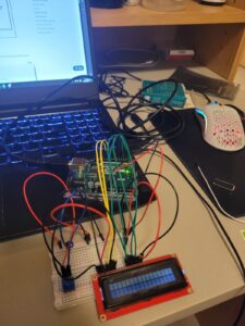
I wanted to give proper physical visual feedback for the player when they use the controller, that’s why I put an LCD onto it. HOWEVER, I did not expect the LCD to require so many pins. The tutorials I’ve been watching use I2C instead :p.
Wiring the whole circuit was like navigating a maze (pun intended). By the end, I’ve got so little space to work with that I am unsure how to hide this in a pretty box.
~~How the Whole Thing Works~~
The Arduino will be the physical controller for the player to move the ball. Once the ball reaches a certain destination, p5 will send a signal to the board. Then, the signal will be read by the board to turn on the LED.
~~Future Actions~~
My next step is to establish a handshake between Arduino and p5. The plan is to have the physical controller output strings: ‘MIDDLE’, ‘LEFT, ‘RIGHT, etc., and replace kb.pressed(‘up’) with the string. This should be particularly simple.
Next, if I am going to attach an LED for an output from p5, I need to find a space for it in my breadboard. Most likely I will need to grab a bigger breadboard and attach everything to that new one.
Last, I need to stylize the game to match a ‘dungeon-crawler’ vibe. We’ll see how it would play out. I’ve got two other projects to work with, and balancing the energy & time is quite a pain. Very excited about this project.
Resources Used
Yes, you can make a Gyroscope using #arduino (youtube.com)
Maze Tutorial Part 1 – YouTube (maze idea inspo)