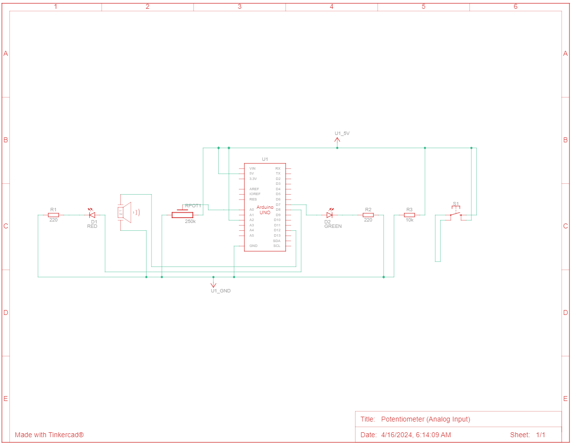
For this assignment, I wanted to recreate the human pulse / heartbeat. The blinking of the LEDs represents the ‘lub-dub’ sound of our heartbeat and the sound of the piezo buzzer represents our heart rate or pulse. When the button is pressed, the LEDs blink in a pattern synchronized with the buzzer. The potentiometer enables users to adjust the speed of the blinking pattern and the pitch of a piezo buzzer. So turning up the potentiometer symbolizes increasing the heart rate.
Video:
Schematic Diagram:
Arduino Code:
const int buttonPin = A2;
const int potentiometerPin = A0;
const int buzzerPin = 12;
const int ledPin1 = 7;   //red
const int ledPin2 = 8;   //green

int buttonState = LOW; //digital input
int potValue = 0;  //analog input
int blinkSpeed = 500; //LED blink speed

void setup() {
  pinMode(buttonPin, INPUT);
  pinMode(buzzerPin, OUTPUT);
  pinMode(ledPin1, OUTPUT);
  pinMode(ledPin2, OUTPUT);
}

void loop() {
  // Read the value of the potentiometer and map it to blink speed range (100-1000 ms)
  potValue = analogRead(potentiometerPin);
  blinkSpeed = map(potValue, 0, 1023, 100, 1000);

  buttonState = digitalRead(buttonPin);
  if (buttonState == HIGH) {  //button pressed
    blinkPattern();
    // Play a tone with frequency based on blink speed
    int buzzerFrequency = map(blinkSpeed, 100, 1000, 500, 1500);
    tone(buzzerPin, buzzerFrequency);
    delay(50);  // Buzz for 100 milliseconds
    noTone(buzzerPin);  // Turn off the buzzer
  } else { //button released
    digitalWrite(ledPin1, LOW);
    digitalWrite(ledPin2, LOW);
    noTone(buzzerPin);
  }
}

void blinkPattern() {
  digitalWrite(ledPin1, HIGH);
  delay(blinkSpeed);
  digitalWrite(ledPin1, LOW);
  digitalWrite(ledPin2, HIGH);
  delay(blinkSpeed);
  digitalWrite(ledPin2, LOW);
}
Overall, I am happy with the outcome. I was relieved to see it finally work because I was trying everything (debugging, restarting circuit, etc.) for 4 hours before I realized my 5V wasn’t connected in properly.
I further want to create more audio-visual displays using LEDs and the piezo buzzer.

