
Introduction
For this project, I wished to use the ultrasonic sensor in some form, especially as it used to be my favorite sensor back when I experimented around with LEGO Mindstorms. I remembered that conceptually, a parking sensor was, in its simplest form, a combination of a digital input (Reverse Gear On/Off) and an analog input (ultrasonic/electromagnetic sensor). So, I decided to emulate that for this project.
Components
- 1 Arduino Uno R3 SMD
- 1 HC-SR04 4-pin Ultrasonic Distance Sensor
- 1 Slideswitch
- 1 Arduino Piezo Buzzer
- 1 10 kΩ Resistor
- 3 330 Ω Resistor
- 1 Red LED
- 1 Green LED
- Jumper Wires (3 red, 5 black, 2 blue, 2 yellow, 2 white, 1 green [in lieu of black, as per convention])
Circuit Schematic and Simulation
The first step was to prepare a circuit schematic on TinkerCAD. Basically, the digital input took the form of a slideswitch feeding into a digital input pin (pin 12) through a 10 kΩ pull-down resistor. Analog Input (which I later discovered was actually a digital input) came from the Echo pin of the Ultrasonic sensor (pin 8), while the ultrasonic pulses were triggered from pin 9. Pin 7 and PWM Pin 5 controlled the digital-controlled Green LED and the analog-controlled Red LED respectively, while the buzzer output was from PWM pin 5.
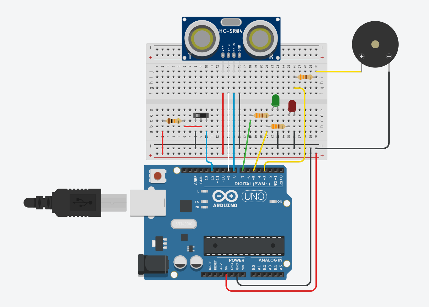 Figure 1: Component Simulation View
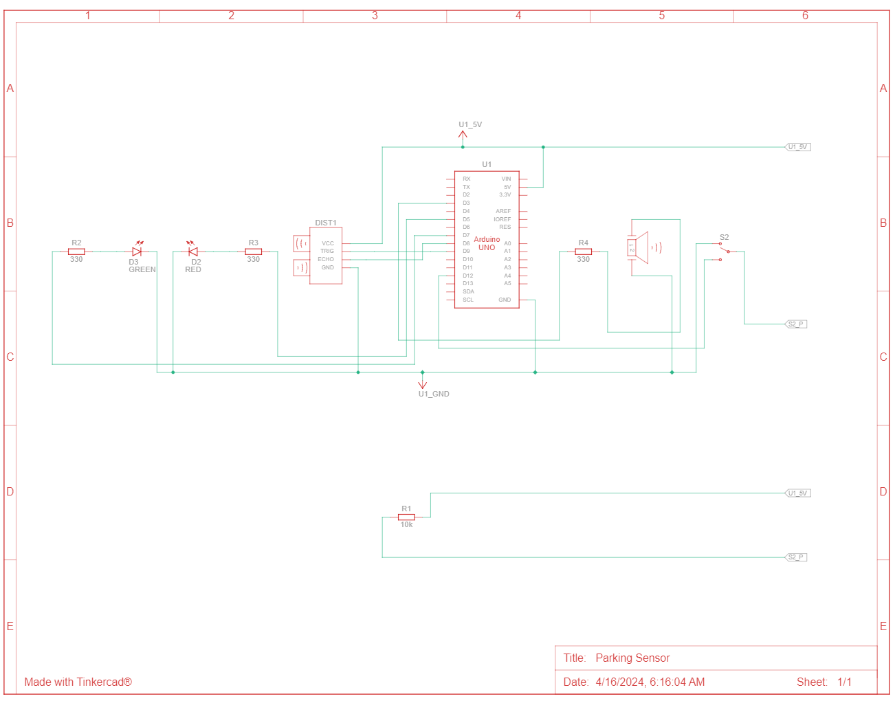 Figure 2: Schematic View
TinkerCAD also has a handy simulation functionality, that even allows to upload the Arduino code and test how the circuit would work under simulator conditions. This definitely helped in fixing bugs before even testing with the actual circuit, and also helped to individually simulate each component before assembling together.
Usage and Implementation
So, the “parking sensor” is first switched on with a slideswitch, which simulates the gear being changed. The green LED turns on, indicating that the sensor is now switched on.
The analog part works by taking the reflection times reported by the ultrasonic sensor, which is converted to distance using the speed of sound. The distance is mapped to the brightness of the red LED and the frequency of repetition of beeps from the buzzer.
The circuit was assembled almost identically to the above schematic. As I had run out of black jumper wires, I substituted using a green jumper wire, as per convention. No other connections made use of green jumper wires. Other than the convention of red for live / black for neutral, I had additional conventions of my own: blue for inputs, white for digital outputs, and yellow for analog outputs.
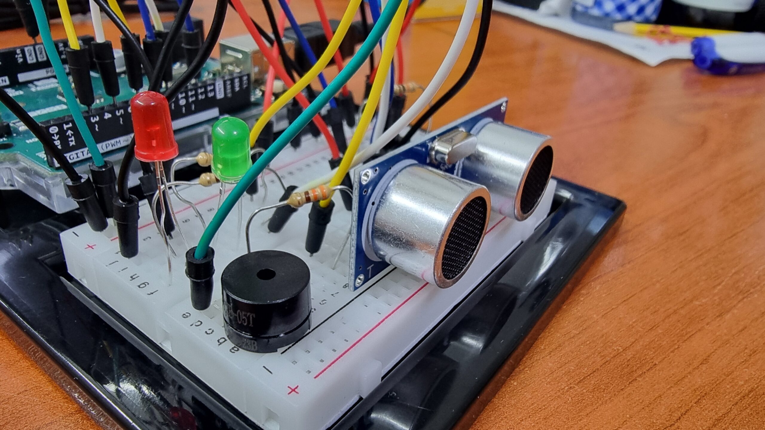 Figure 3: Front View
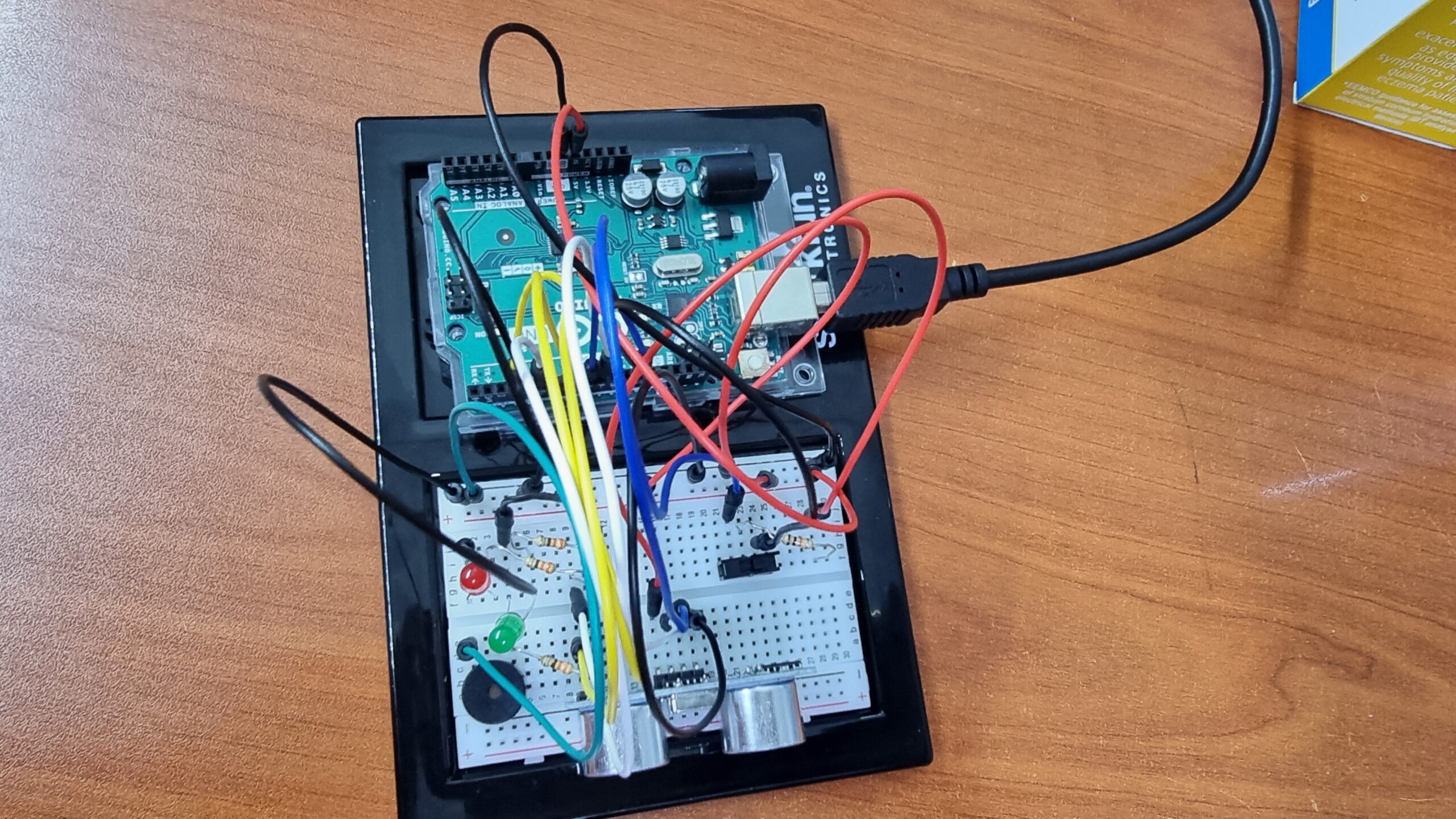 Figure 4: Top View
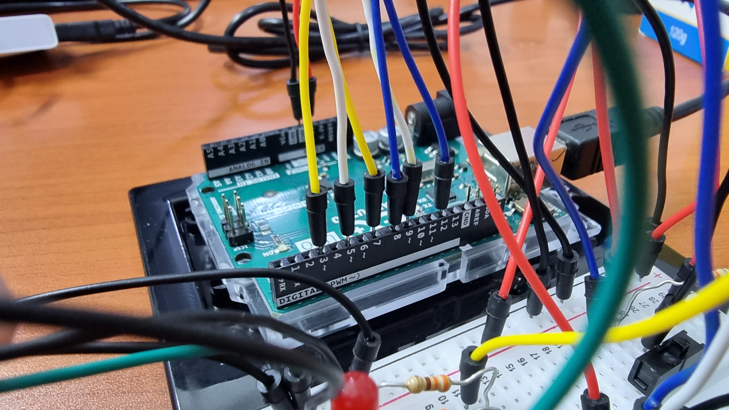 Figure 5: Arduino Pins Connection
Code
//Global
int distance = 0;
int duration = 0;
int brightness = 0;
int minDistance = 5;
int maxDistance = 30;

//Pins
int digitalIn = 12;
int trigger = 9;
int echo = 8;
int green = 7;
int red = 5;
int buzzer = 3;

// Ultrasonic Function
long readUltrasonicDistance(int triggerPin, int echoPin)
{
  pinMode(triggerPin, OUTPUT);  // Clear the trigger
  digitalWrite(triggerPin, LOW);
  delayMicroseconds(2);
  // Sets the trigger pin to HIGH state for 10 microseconds
  digitalWrite(triggerPin, HIGH);
  delayMicroseconds(10);
  digitalWrite(triggerPin, LOW);
  pinMode(echoPin, INPUT);
  // Reads the echo pin, and returns the sound wave travel distance in centimeters
  return 0.01723 * pulseIn(echoPin, HIGH);
}

void setup()
{
  pinMode(digitalIn, INPUT);
  pinMode(green, OUTPUT);
  pinMode(red, OUTPUT);
  pinMode(buzzer, OUTPUT);
  Serial.begin(9600);
}

void loop()
{
  if (digitalRead(digitalIn) == HIGH) {
    digitalWrite(green, HIGH);
    distance = readUltrasonicDistance(trigger, echo);
    if (distance < maxDistance && distance != 0) {
      duration = map(distance, 0, maxDistance, 5, 60);
      brightness = map(distance, 0, maxDistance, 220, 0);
      analogWrite(red, brightness);
      tone(buzzer, 523); // play tone C5 = 523 Hz for 100 ms
      delay(100);
      if (distance > minDistance){
        noTone(buzzer);
        delay(duration); // Wait for (duration) millisecond(s)
      }
    } else {
      analogWrite(red, 0);
      noTone(buzzer);
    }
    Serial.println(distance);
    delay(10); // Wait for 10 millisecond(s)
  } else {
    digitalWrite(green, LOW);
    analogWrite(red, 0);
    noTone(buzzer);
  }
}
The code is not too different from the examples we did in class, other than the function for the Ultrasonic Sensor. For that, I followed this helpful tutorial on the Arduino Project Hub.
Showcase
Reflections
I enjoyed working on this project, although figuring out the Ultrasonic Sensor and debugging it did take a while. I was actually impressed by how sensitive the sensor turned out to be, and how it managed to sense even objects passing perpendicular to its field of view (as demonstrated towards end of demo). Thus, other than being a parking sensor, it does actually work as a rudimentary safety sensor, being able to detect pedestrians as well.
I originally wished to include another LED (a yellow one that would fade with distance and a red that would trigger at a threshold minimum distance), but I ran out of black jumper wires and viable space on the breadboard, so I cut it down to two. Also, not shown in the showcase itself is an issue that the circuit has with powering off. Possibly due to the built-in delays, it takes a while between the switch turning to off position and the LEDs themselves actually turning off.
Also, I realized only later that Ultrasonic Sensors technically are digital inputs, but since they transduce an analog measurement into a digital input, I felt that it worked for the scope of this project.