
Introduction
For this week, I tried to imagine something complex to do, but due to creative bankruptcy, I could not imagine any interesting mechanisms for this Arduino. Although, I still wanted to experiment with what we have learned in class so far.
When we were experimenting with the photoresistor, I was curious to see what kind of patterns I could make with the use of the device, LEDs, and the mapping function. Thus, I came with the idea of doing a volume meter inspired light detector.
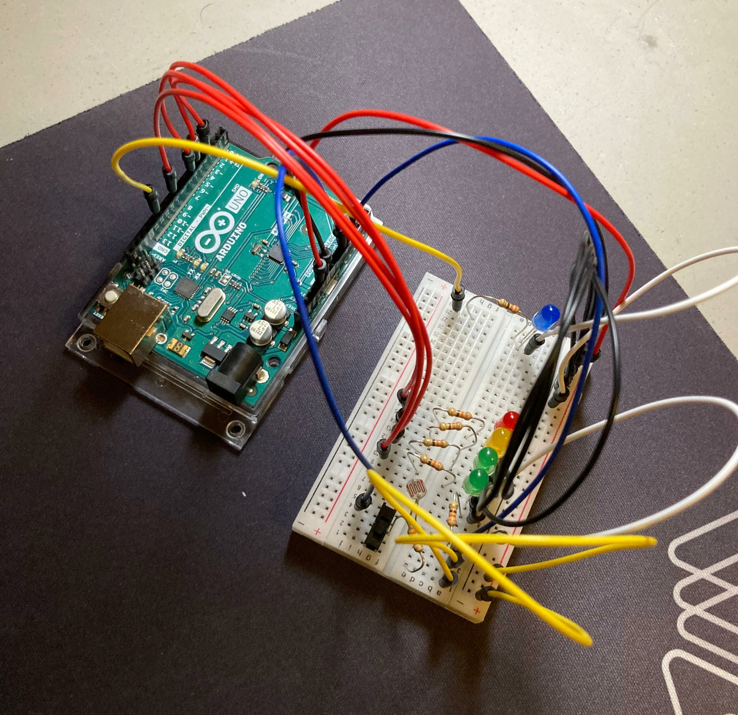 Figure #1: Arduino made in person.
Materials
-
- 7 330-ohm resistors.
- 2 green LED lights.
- 1 yellow LED light.
- 1 red LED light.
- 1 blue LED light.
- A breadboard.
- 8 red jumper wires (due to being low in red jumper wires, three are yellow).
- 7 black jumper wires (again, due to being low, 2 are white).
- 2 blue jumper wires.
- An Arduino board with, 5V, GND, analog and digital output and input.
- A slideswitch.
Implementation & Usage
Once all the materials are set up like in the schematic and the Arduino is powered, the user can do either of the following according if the slideswitch is ON or OFF:
1. If the slideswitch is ON, a blue LED will indicate this state. In this mode, if a light source is redirected to the photoresistor, the LEDs will turn on, like a volume meter, depending on the strength of the source.
2. If the slideswitch is OFF, the blue LED light will be off, indicating this state. In this mode, a non-interactable sequence where each LED light will be displayed, where they will be turning ON and OFF in a 0.5 second basis.
Both modes can be interrupted at any time.
Schematics
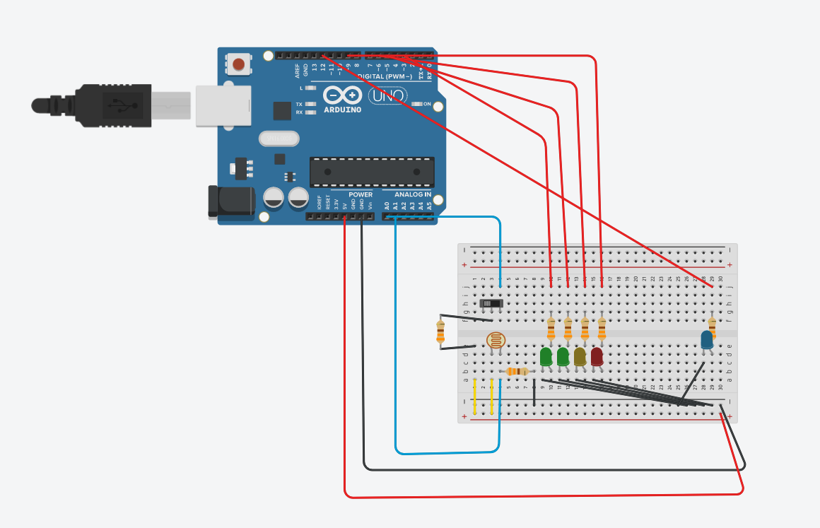 Figure #2: Schematic #1 made in Tinkercad.
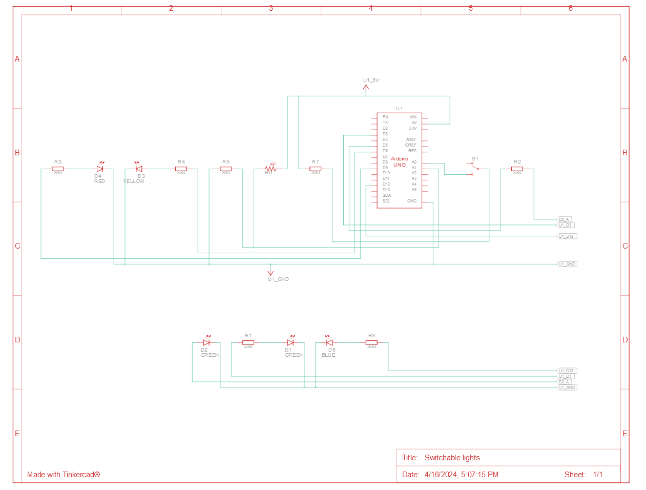 Figure #3: Schematic #2 made in Tinkercad.
Code
For the coding, I used the blocks GUI from Tinkercad, and then transform it into code to change it according to my necessities, as well as add some comments to it to further explain some functionalities.
//We will only use two variables for this Arduino set up:
//Brightness is to receive the analog values from the photoresistor, to use to turn ON the LEDs.
//Switchstate will alternate between states depending on the analog valaue received.

int brightness = 0;
int switchstate = 0;

void setup()
{

  // Preparing the Arduino and variables initialization.
  pinMode(A0, INPUT);
  pinMode(A1, INPUT);
  Serial.begin(9600);
  pinMode(3, OUTPUT);
  pinMode(5, OUTPUT);
  pinMode(6, OUTPUT);
  pinMode(9, OUTPUT);
  pinMode(12, OUTPUT);

  brightness = 0;
  switchstate = 0;
}

void loop()
{
  switchstate = analogRead(A0);

  // According to the amount of light received by the photoresistor, it will turn on the LEDs. For example,
  //if the light source is too strong, all LEDs will turn on, if it is too low, either 1 or 2 will be ON.

  if (switchstate > 1013) {
    digitalWrite(12, HIGH); // Blue LED indicates light mode.
    brightness = analogRead(A1); //Receive values from the photoresistor.
    Serial.println(brightness); //and print it to serial.
    if (brightness > 100) {
      analogWrite(3, map(brightness, 0, 1023, 0, 300)); //First green LED will be turn on and its intensity will depend on the intensity of the light source. Also, we map the values received since if it is too high, then it will basically loop; mapping makes sure that it always states in a range.
      if (brightness > 200) {
        analogWrite(5, map(brightness, 0, 1023, 0, 300)); //Second green LED will be turn on and its intensity will depend on the intensity of the light source. The rest is the same.
        if (brightness > 300) {
          analogWrite(6, map(brightness, 0, 1023, 0, 300));
          if (brightness > 400) {
            analogWrite(9, map(brightness, 0, 1023, 0, 300));
          } else {
            digitalWrite(9, LOW);
          }
        } else {
          digitalWrite(6, LOW);
        }
      } else {
        digitalWrite(5, LOW);
      }
    } else {
      digitalWrite(3, LOW); //If it fails to meet the requirement, the it will turn OFF without exceptions. It is the same for the rest of LEDs.
    }


  } else {
    // Each LED gets turn on and off in order.
    digitalWrite(12, LOW); // Blue LED gets shut down.
    digitalWrite(3, HIGH);
    delay(500); // Wait for 500 millisecond(s)
    digitalWrite(3, LOW);
    digitalWrite(5, HIGH);
    delay(500);
    digitalWrite(5, LOW);
    digitalWrite(6, HIGH);
    delay(500);
    digitalWrite(6, LOW);
    digitalWrite(9, HIGH);
    delay(500);
    digitalWrite(9, LOW);
    Serial.println(switchstate);
  }
}
Showcase
In this video, I show how the Arduino looks and operates. Please keep in mind that the color of some jumper wires had to be mixed up (at least strategically) due to material constrains, in order to still convey the positive and negative connections.
Challenges
The biggest challenge in this Arduino was, actually, making the photoresistor to work. The reason of this difficulty was that I had forgotten how to set up the photoresistor properly, even though we were taught how to do so in class. Although, with a YouTube video and quick review of the slides, I was able to pick up again what I needed to do and not question myself why I was getting a consistent analog value of 1024 from my photoresistor.
Reflection
I am feeling that I am going a bit bankrupt creatively. I do admit that this Arduino took me time to develop, but the many ideas I had in my mind are still not able to come into fruition. Likewise, I personally feel that this is like the previous scenario in the first half of this semester, where I was mostly experimenting with the provided tools in order to have a greater idea of what is possible to do. It is likely it will happen in this case, but still, I wish I could come with more ideas to develop more curious devices.
Nevertheless, I did learn something new from this Arduino, like how to effectively map some values and how to set up properly a device (ignoring the selection of colors of the jumper-wires of course) to capture values from two points: the photoresistor and the slideswitch.
Thanks for reading this and have a happy day.