
Concept
This week, I set out to blend analog and digital elements into a single creative project, leading me to design a reaction game inspired by the “reaction lights” game by Lummic I stumbled upon a few months ago. In this game, players test their reflexes by pressing a button as soon as its corresponding light turns on.
I integrated a tricolor RGB light that serves as a real-time indicator of the player’s reaction time—green signals excellent speed, blue is moderate, and red denotes a slower response. To add a twist and enhance engagement, I included a potentiometer to adjust the game’s difficulty, effectively changing the time intervals that define the three color responses. This setup not only challenges players but also gives them control over the complexity of the task, making each round adaptable and uniquely challenging.
Images
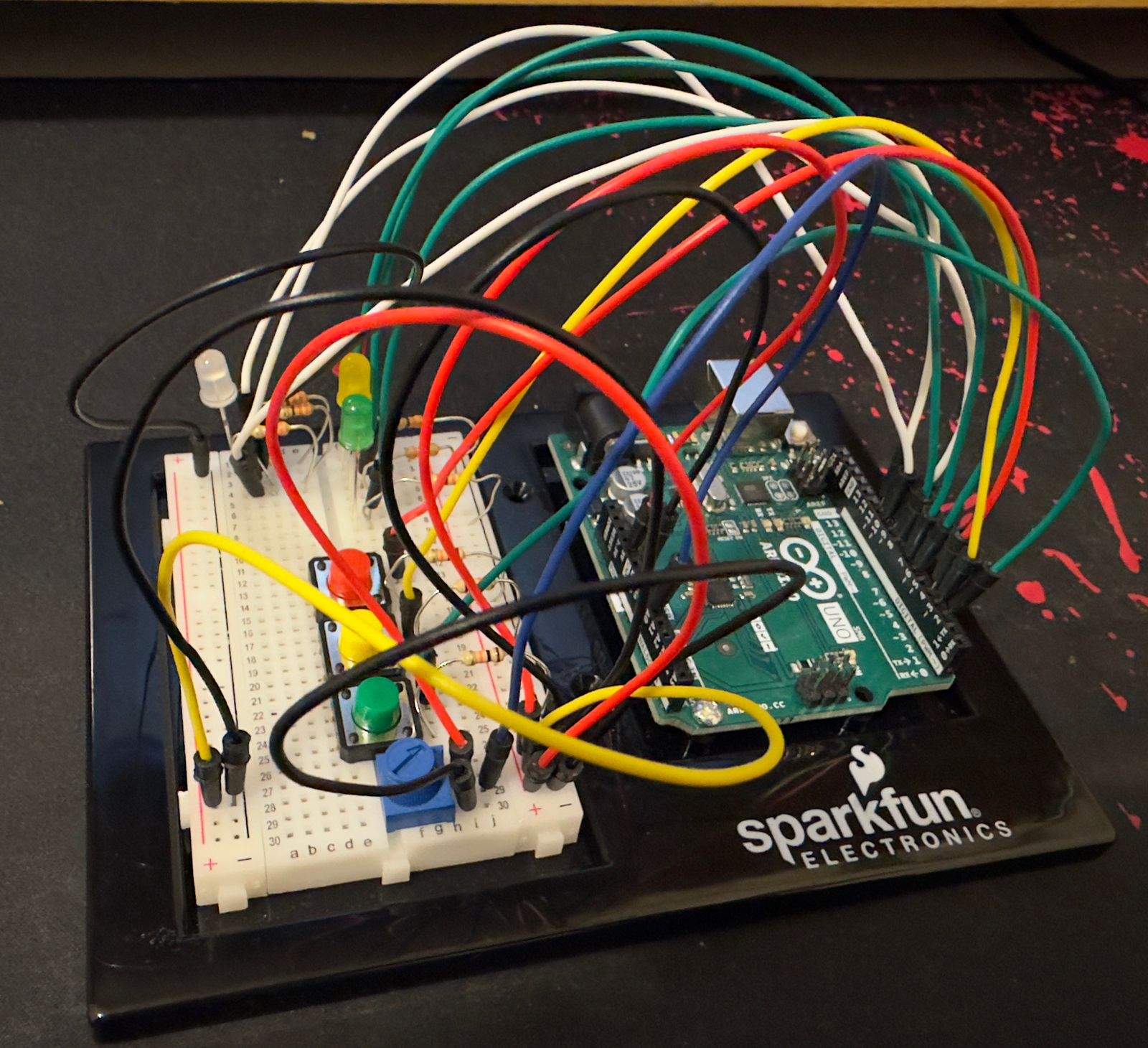
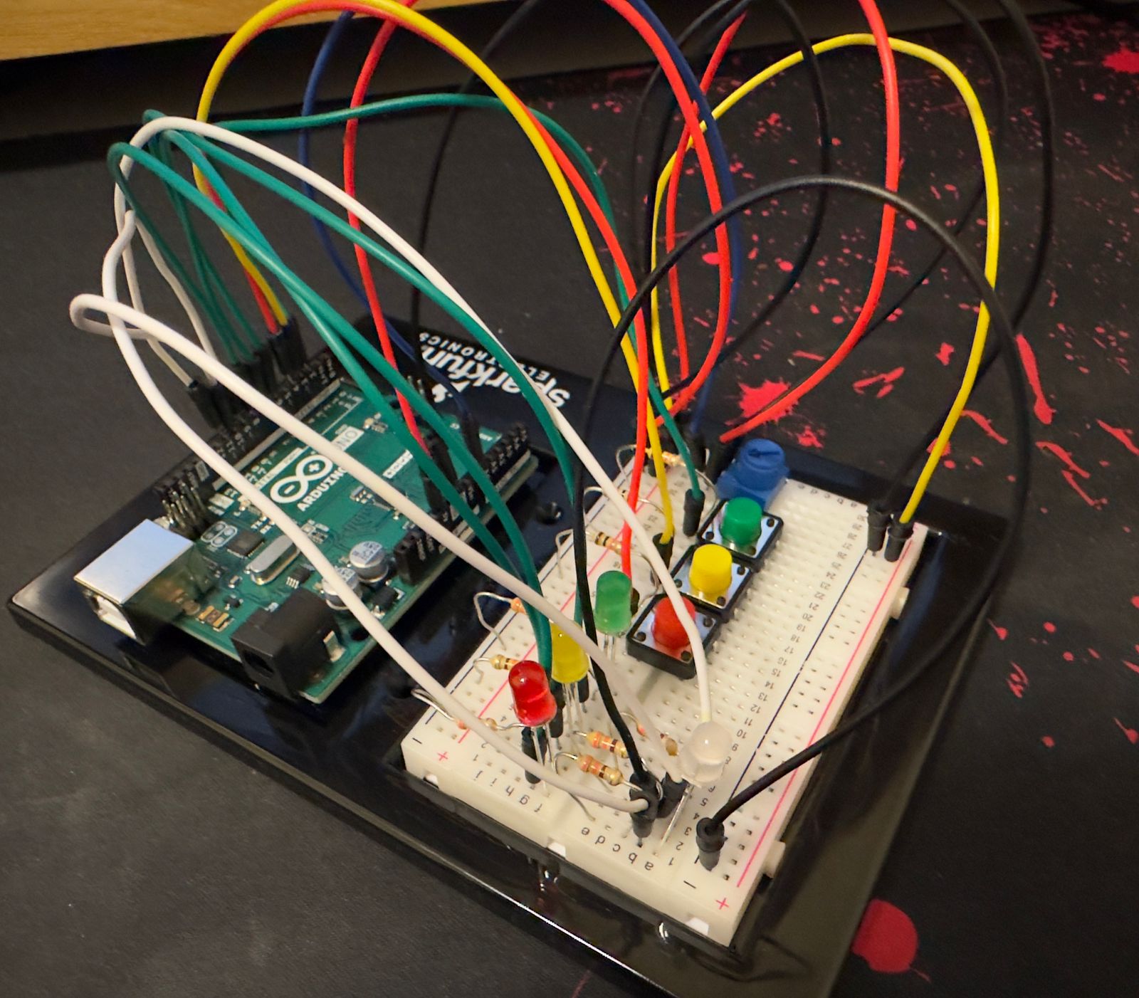
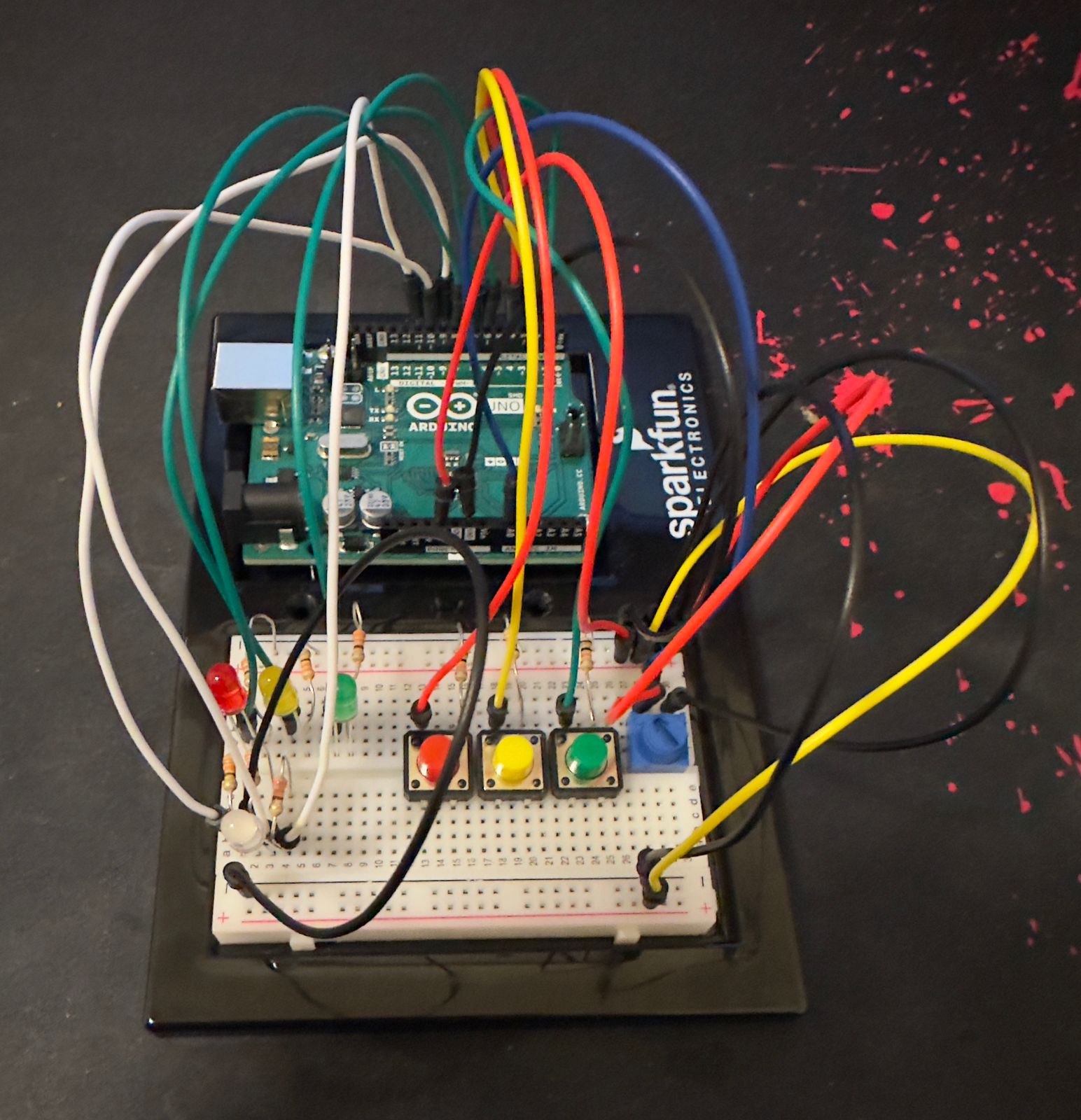
Components Used
- Arduino Uno
- Tricolor RGB LED
- Pushbuttons (3)
- Resistors:
- 330 ohm resistors (3)
- 10k ohm resistors (3)
- Potentiometer
- Breadboard
- Jumper Wires
Circuit Setup
- RGB LED
- The common cathode of the RGB LED connects to the Arduino’s ground.
The red, green, and blue anodes are connected to PWM-capable digital pins (9, 10, and 11) through 330-ohm resistors to limit current.
- The common cathode of the RGB LED connects to the Arduino’s ground.
- Pushbuttons
- Each button is connected to one of the digital input pins (2, 3, and 4).
The other side of each button is linked to the ground through a 10k-ohm resistor to ensure the pin reads LOW when the button is unpressed.
- Each button is connected to one of the digital input pins (2, 3, and 4).
- Potentiometer
- One outer pin connects to the 5V on the Arduino, and the other to the ground. The middle wiper pin is connected to analog input A0, allowing the Arduino to read varying voltage levels as the potentiometer is adjusted.
Video
Code
void setup() {
  for (int i = 0; i < 3; i++) {
    pinMode(buttonPins[i], INPUT_PULLUP);
    pinMode(ledPins[i], OUTPUT);
  }

  // Set up RGB LED pins as outputs
  pinMode(redPin, OUTPUT);
  pinMode(greenPin, OUTPUT);
  pinMode(bluePin, OUTPUT);

  Serial.begin(9600);
}
Input pins (buttonPins): Configured with INPUT_PULLUP to use the internal pull-up resistors, ideal for buttons.
Output pins (ledPins and RGB LED pins): Set as outputs to control LEDs.
void loop() {
  int potValue = analogRead(potPin);
  // Adjust the max delay range for more sensitivity
  int maxDelay = map(potValue, 0, 1023, 5000, 2000);
  Serial.print("Potentiometer Value: ");
  Serial.print(potValue);
  Serial.print(", Max Delay (ms): ");
  Serial.println(maxDelay);

  if (!gameActive) {
    gameActive = true;
    targetLed = random(0, 3);
    digitalWrite(ledPins[targetLed], HIGH);
    startTime = millis();
    Serial.print("Game started, respond before ");
    Serial.print(maxDelay);
    Serial.println(" ms for the best score!");
  }

  if (digitalRead(buttonPins[targetLed]) == LOW) {
    // Debounce by ensuring at least 50 ms has passed
    if (millis() - startTime > 50) {
      unsigned long reactionTime = millis() - startTime;
      Serial.print("Reaction Time: ");
      Serial.println(reactionTime);

      setColorFromReactionTime(reactionTime, maxDelay);
      // Show result for 1 second
      delay(1000);
      // Turn off RGB LED
      setColor(0, 0, 0);
      digitalWrite(ledPins[targetLed], LOW);
      gameActive = false;
      delay(1000);
    }
  }
}
There are 3 main steps in the loop function:
- Read Potentiometer: Determines the difficulty level by reading the potPin and mapping its value to define maxDelay, the maximum time allowed for a response.
- Game Control
- If gameActive is false, the game starts by picking a random LED to light up and marks the start time.
- If the corresponding button is pressed (digitalRead(buttonPins[targetLed]) == LOW), it checks for debouncing (to ensure the button press is genuine) and then calculates the reaction time.
- Serial Output: Outputs debug information such as potentiometer value and maximum delay time to the serial monitor.
void setColorFromReactionTime(unsigned long reactionTime, int maxDelay) {
  // Set RGB LED color based on reaction time as a fraction of maxDelay
  if (reactionTime < maxDelay / 5) {
    // Fast: Green
    setColor(0, 255, 0);
  } else if (reactionTime < maxDelay / 2) {
    // Moderate: Blue
    setColor(0, 0, 255);
  } else {
    // Slow: Red
    setColor(255, 0, 0);
  }
}
It is based on the player’s reaction time, this function sets the color of the RGB LED:
- Fast Response: Less than 1/5 of maxDelay, the LED turns green.
- Moderate Response: Less than 1/2 but more than 1/5 of maxDelay, it turns blue.
- Slow Response: Slower than 1/2 of maxDelay, it turns red.