
Concept:
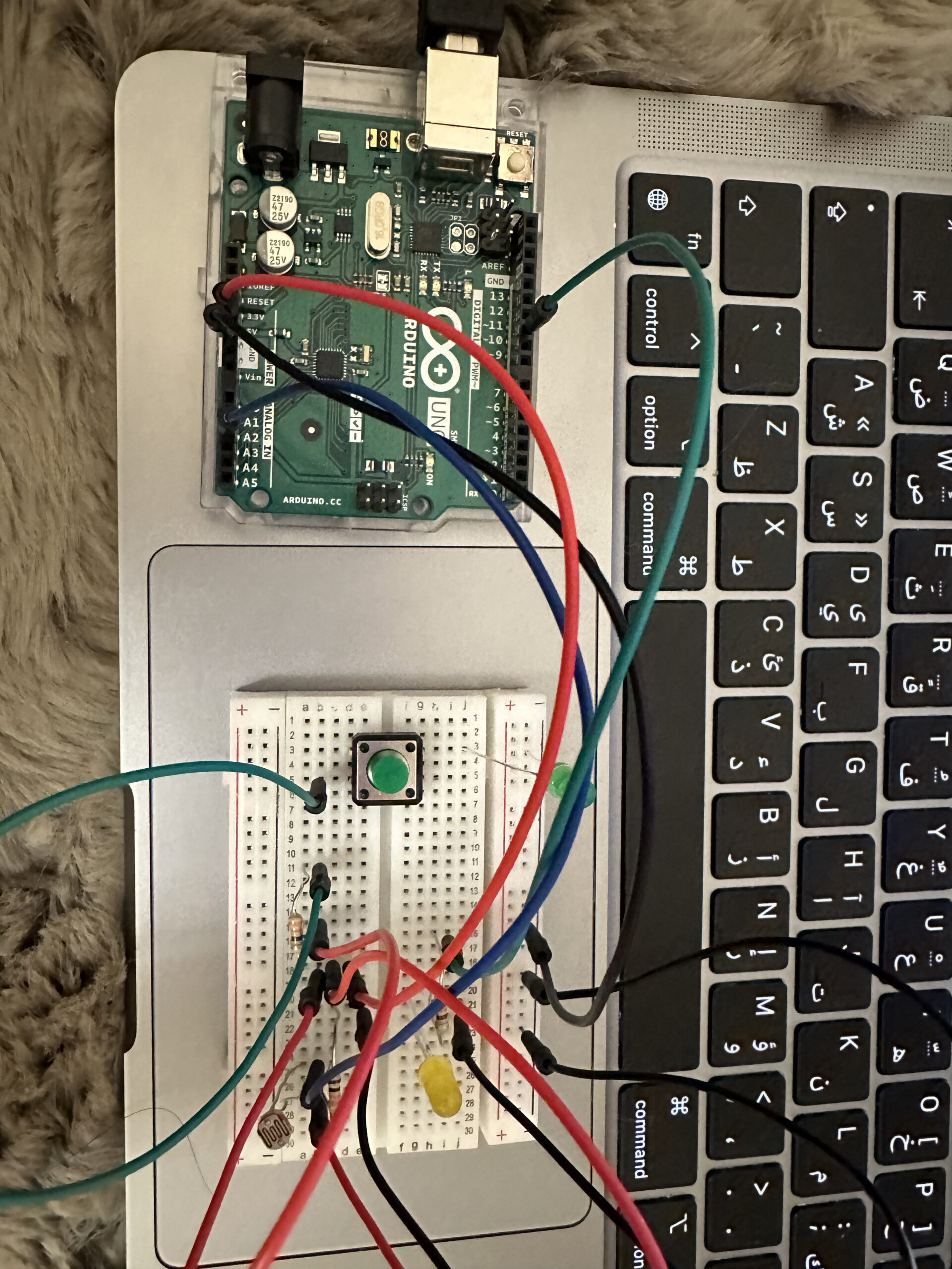
The idea of this assignment is to have differently controlled LED lights. In this example, they act as lights outside of an airplane bathroom. When the bathroom is occupied, the yellow light is either on or off (digital) . When it is unoccupied, the green LED senses that there is no light in the room and therefore turns on the green light gradually (analog). This can also be used in a parking lot which depicts whether a parking is available or not.
Watch here:
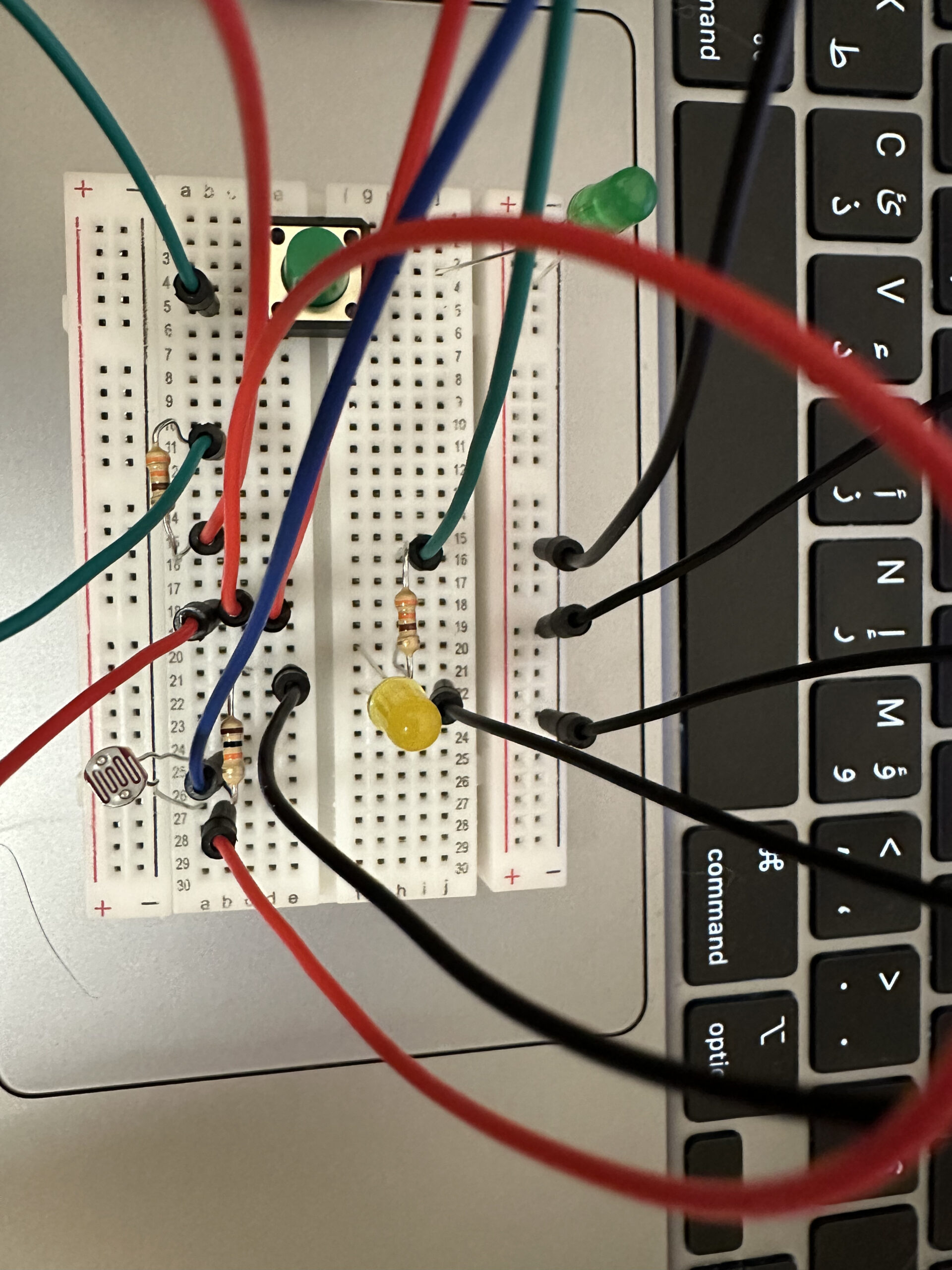
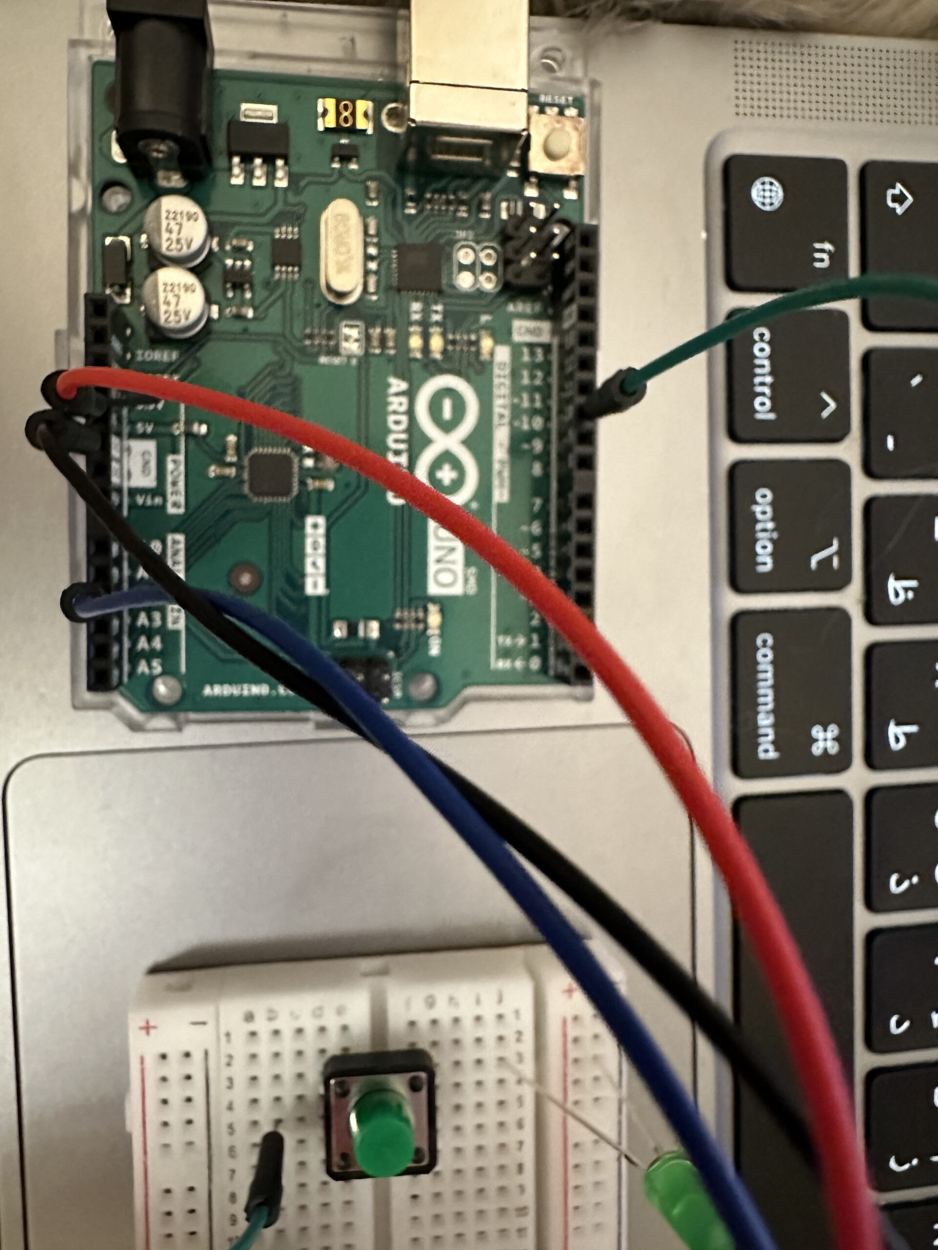
For the analog pin, I used pin 10, with A2 used for the input. I used both resistors for it, the 10K and 330 ohm ones. As for the digital pin, it only required the 330 ohm resistor.
Code:
int led = 10;         // the PWM pin the LED is attached to
int brightness = 0;  // how bright the LED is

// the setup routine runs once when you press reset:
void setup() {
  Serial.begin(9600);
  // declare pin 10 to be an output:
  pinMode(led, OUTPUT);
}

// the loop routine runs over and over again forever:
void loop() {
  int sensorValue = analogRead(A2);

  sensorValue = constrain(sensorValue, 30, 210);

  analogWrite(led, sensorValue/4);

  brightness = map(sensorValue, 30, 210, 0, 255);

  Serial.println(sensorValue);

  // wait for 30 milliseconds to see the dimming effect
  delay(30);
}
Difficulties:
As I was working on it, I struggled so much with trying to get both LED lights to work at the same time as they both needed power from 5V. A few LED lights were burnt while figuring that out. Eventually, I knew how to fix that by connecting two wires to the 5V wires then connecting those to each input (button and photoresistor).