
As I am still experimenting with physical computing and coding for Arduino, I tried to emphasize simplicity for this week’s assignment. The concept for this week’s assignment is a simple lighting system using both digital and analog sensors. This lighting system has two LEDs, one attached to a manual system while the other an automatic one. This gives users the freedom to either choose to use only one light system or both. I was inspired to create this dual lighting system because I often feel like versatility in lighting is important not only to give a space more dimension but to also make our lives easier. With such a system, users are able to ensure that they have the right lighting for the circumstance they are in but also have the freedom to control it the way they see fit. Below you can find the schematic diagram of the system I created: 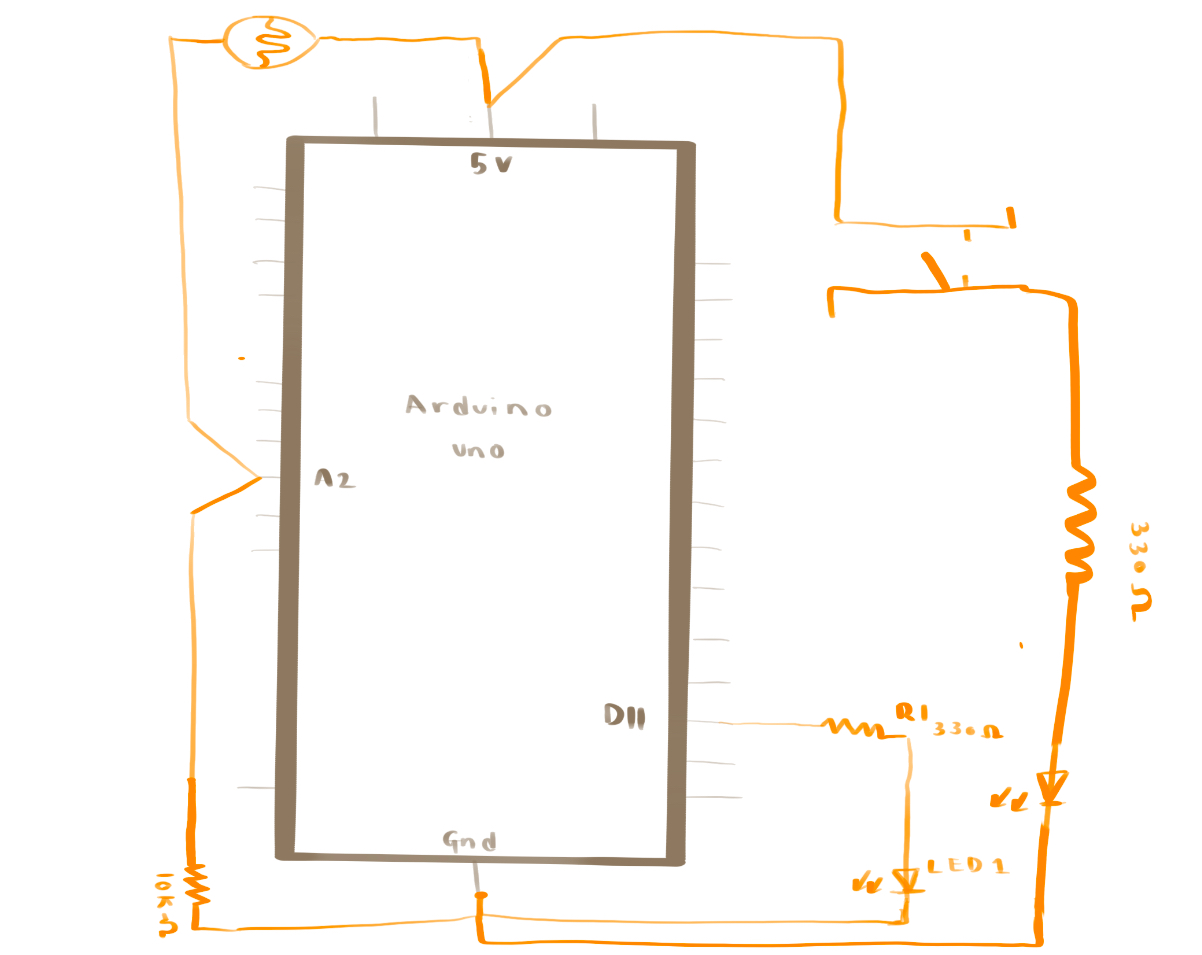
(warning, schematic diagram might not be comprehendible!)
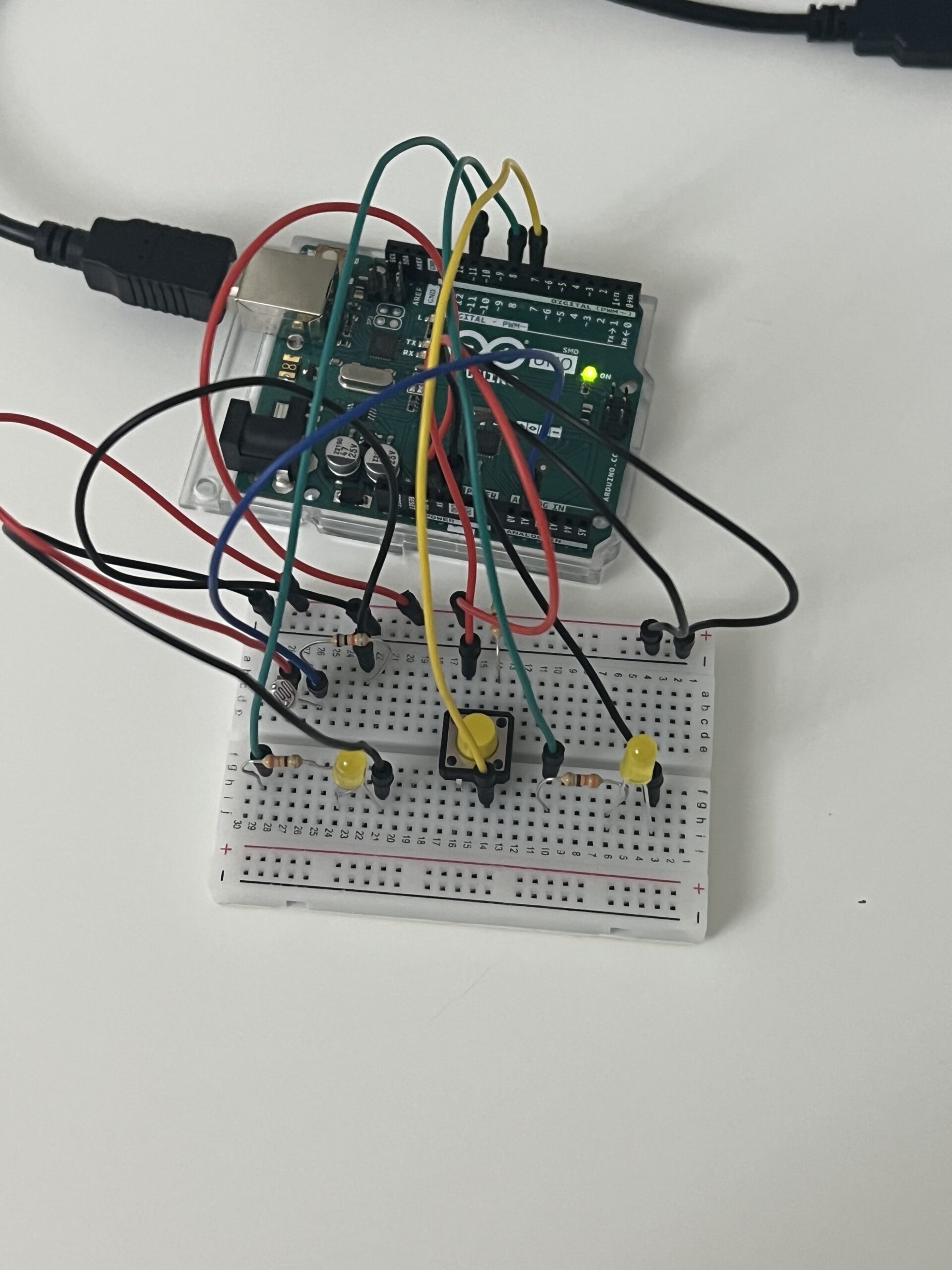
After finalizing the schematic, I began building the actual system using the Arduino uno. The components used in this assignment were 11 wires, 2 LEDs, one button, one photo-resistor, 1 10K resistors, and 3 330 resistors. These components helped to create an efficient dual lighting system that helps users have a good balance between manual control and automatic adjustment of the lighting. I pinned the 5v and the ground to the positive and negative ends of the bread board to act as a “main ground” for the rest of the circuits on the bread board. For the button part of the circuit, I placed one end of the red wire to connect to the positive end of the board and one end of the 330 resistor. The other end of the 330 resistor is placed at the negative end of the bread board to ground it. The wire attached to 5v is attached to one end of the button, while the other end of the button is attached to pin 7. This wire is connected to another 330 resistor, which is attached to the LED A that is used for the “manual” system. The other end of LED A is grounded in the negative end of the bread board. For the photo-resistor, one end of it is attached to the positive end of the bread board where 5 voltage is. The other end of the photo-resistor is a wire that is attached to A1, which is an analog pin. That wire is connected to a 330 resistor. One side of the resistor connects to the wire that is connected to the negative end of the bread board where it is grounded. For LED B, which is the automatic part of the circuit, one side is connected to the negative end of the bread board where it is grounded and the other side is connected to a 330 resistor. The other end of the 330 resistor is connected to a wire, which is attached to pin 11. This makes the full manual and automatic light system. Below, you can find an image of the built system based off of the schematic diagram:

Programming the LEDs to function as intended required code for each. The first LED was programmed to turn on and remain on when the button was pressed and off and stay off when the button was pressed again, representing the digital sensor aspect of the system. The second LED was designed to activate and deactivate automatically in response to the light levels detected by the photo-resistor, which represents the analog sensor aspect of the system. While the automatic adjustments based on the light levels might appear to be the most complex part of the system, it was actually the digital control of the first LED that presented the most challenges. I had to review class materials several times, go over examples, and watch youtube videos to get to the vision I wanted to have for this system. The youtube video that ultimately helped me to get to the vision I wanted was Robotics Back-End’s Arduino- Turn LED On and Off With Push Button video, which has been cited at the bottom of this blog post. Therefore, that is one part of code that I am particularly proud of.
void loop() {
//BUTTON
int buttonState = digitalRead (7);
// Check if enough time has passed since the last button state change
if (millis() - lastTimeButtonStateChanged >= debounceDuration){
   // Check if the button state has changed
  if (buttonState != lastButtonState){
    // Update the last time the button state changed
    lastTimeButtonStateChanged = millis();
    lastButtonState = buttonState;

    // Toggle the LED state when the button is pressed
    if (buttonState == LOW){ //If button is not pressed
      if (ledState == HIGH){ //and LED is on,
        ledState = LOW; //make LED turn on
      } else{ //if button is pressed,
        ledState = HIGH; //Make the LED turn on
      }
       // Update the LED controlled by the button
      digitalWrite(8, ledState);
   }
  }
 }
}
As you can see, the code corresponding to the button is intricate, utilizing a lot of ‘if’ statements to achieve the desired on and off effect when the button is pressed. You can see this and the whole system in action below:
In terms of improvements, I would have definitely liked to have only one LED to make it as similar to a typical light system as possible. I initially thought of coding one LED to have both the manual and automatic light systems but I, unfortunately, was not able to get it to function the way I wanted it to. Therefore, that is something I would like to improve on for the future. However, I have to say even with the countless days spent on this assignment, I genuinely enjoyed getting to the final product and seeing my vision come to life some way or another. As I mentioned earlier in this blog post, I was still adjusting to physical computing and using Arduino, which is why I wanted to create something simple. Creating this lighting system, although simple, was a big step into seeing not only the ways in which you can use physical computing components to create things that you envision but it has also allowed me to see the ways in which it can be used to fix real world problems. Even if this was obvious to me, it was only when I started to create things of my own did I see the potential and reach of physical computing in helping fix many of the problems people are facing today, which is something I am glad to have seen for myself.
References:
[Robotics Back-End]. (2022, February 28). Arduino – Turn LED On and Off With Push Button [Video]. Youtube. https://www.youtube.com/watch?v=ZoaUlquC6x8