
Concept:
As soon as I saw the instructions for this assignment, I knew that I would like to use the potentiometer creatively. The potentiometer reminded me of the water faucet in my grandmother’s backyard which controls the amount of water being released. Then, randomly, I got reminded that my grandmother loves plants. So, I wanted to do something related to plants for the concept. Then, I decided to do something that is related to “watering the plant”. There is always an adequate amount of water to give the plant. If we give too much water, the plant will die. If we give too little water, the plant will also die. So, I decided to make my project for this assignment with the concept of an “indicator” that shows the plant’s feeling towards the amount of water given (too little, just right, too much) through LED lights based on the water given to it (value of potentiometer).
Arduino Diagram (Schematic):
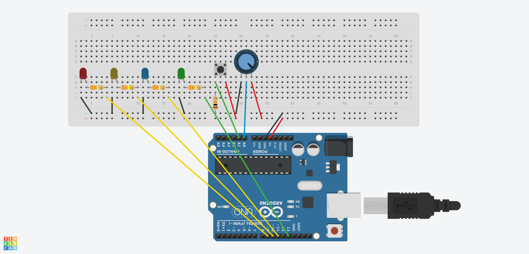
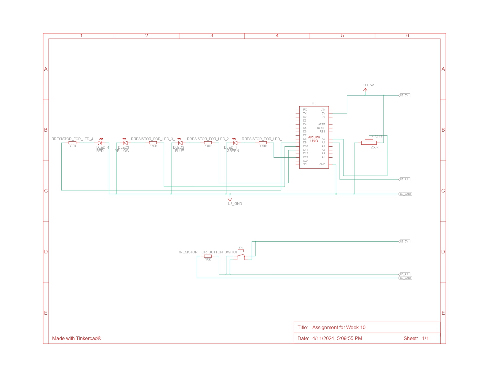
As you can see from the schematic diagram above, there are three LED lights associated with the potentiometer and 1 LED light associated with the button switch. The green LED light (led1), which is associated with the button switch is attached to pin 13. Then the red (led4), yellow(led2), and blue(led 3) LED lights, which are associated with the potentiometer, are connected to pins 9,10, and 11 respectively. The red jumper wires are used to indicate 5V connections and the black jumper wires are used to indicate the GND connections. Power from the 5V pin is distributed to both the digital sensor (the switch) and the analog sensor (the potentiometer). Data from the switch is sent to the A1 pin, while data from the potentiometer is sent to the A0 pin. Then, all circuits complete their path back to the GND pin.
Arduino Code:
// variables
//declaring and initializing brightness to 0
int brightness=0;

//the pin the LEDs are attached to:
//related to the switch
int led1=13; //green light
//related to the potentiometer
int led2=11; //yellow light
int led3=10; //blue light
int led4=9; //red light


void setup() {
//declaring input and output
  pinMode(A1,INPUT);
  pinMode(led1, OUTPUT);
  pinMode (led2,OUTPUT);
  pinMode(led3, OUTPUT);
  pinMode(led4, OUTPUT);

}

void loop() {
  int sensorValue= analogRead(A0);
  int buttonState= digitalRead(A1);
  // turning on and off led1 using the switch:

  //led 1 is turned on when the button is pressed;
  if (buttonState== HIGH){
    digitalWrite(led1, HIGH);
  } else{
    digitalWrite(led1, LOW);
    //making sure other LED lights are switched off
    analogWrite(led2, 0);
    analogWrite(led3, 0);
    analogWrite(led4, 0);
  }
//related to the potentiometer
  if ((sensorValue < 341)&&(buttonState==HIGH)){
   //mapping the brightness for the fade effect (bright>> dim)
    brightness= map (sensorValue,341,0, 0, 255);
    //turning on the led2 when the potentiometer's value is lower than 341
    analogWrite(led2, brightness);
    //ensuring other lights are not turned on
    analogWrite(led3,0);
    analogWrite(led4,0);
  }
  else if ((sensorValue <682)&&(buttonState==HIGH)){
    //mapping the brightness for the fade effect (dim>> bright)
    brightness= map (sensorValue,341,682, 0, 255);
    //turning on the led3 when the potentiometer's value is in between 341 and 682
    analogWrite(led3, brightness);
    //ensuring other lights are not turned on
    analogWrite(led2,0);
    analogWrite(led4,0);
  }
  else if ((682 <sensorValue)&&(buttonState==HIGH)){
    //mapping the brightness for the fade effect (dim>> bright)
    brightness= map (sensorValue,682,1023, 0, 255);
     //turning on the led4 when the potentiometer's value is greater than 681
    analogWrite(led4, brightness);
    //ensuring other lights are not turned on
    analogWrite(led2,0);
    analogWrite(led3,0);
  }

}
As shown above, I initially declared and initialized the brightness to 0, and set up variables for the LED lights attached to their respective pins. I then designated these as outputs and input in the setup() function. In the loop() function, I declared sensorValue and buttonState to adjust the LED lights based on input from the potentiometer and the switch. Utilizing if-else statements, I controlled the LED lights based on this input. For example, led1 turns on only if the button is pressed, indicating that the user wants to start ‘releasing’ water. For the other LEDs, I divided the potentiometer’s range of 1023 into three, setting specific ranges for each light: if the value is less than 341, the yellow LED (LED 2) lights up; if the value is between 341 and 682, the blue LED (LED 3) activates; and if it’s above 682, the red LED (LED 4) turns on.
A notable aspect of this if-else statement is the use of the map() function to create a fade effect from dim to bright or vice versa. As the potentiometer’s value increases within LED 2’s range, the light dims, indicating that the ‘water level’ is moving away from ‘too little.’ In contrast, LEDs 3 and 4 brighten as their ranges are reached, signaling an increase in water level.
Another key point is that every lighting condition includes buttonState==HIGH. I included this to ensure that the LEDs only activate when the button is pressed, signifying that water is being dispensed.
Built circuit based on the schematic diagram
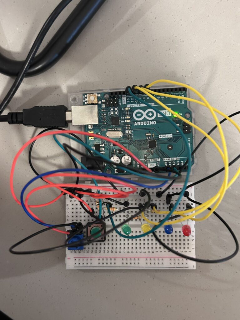 circuit built
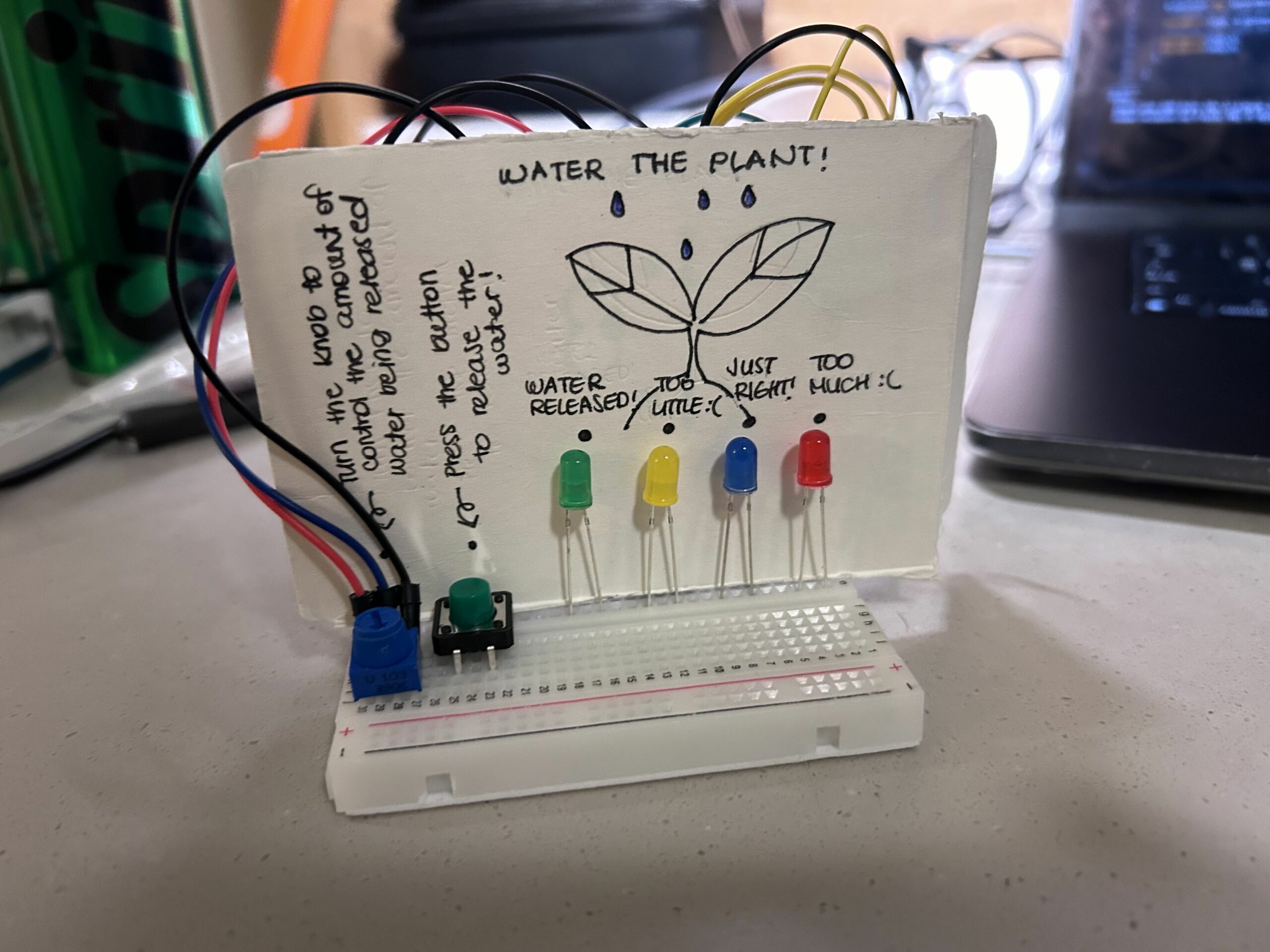 final product with illustrations
Demonstration of the Final Outcome:
It was a little hard for me to control the potentiometer as I had taken this video by myself. However, you could see the lights getting dimmer or brighter as I control the potentiometer!
Challenges and Reflection:
Overall, as always, I enjoyed doing this assignment. I am a person who is new to Arduino and circuits. So, it was quite challenging for me to fully understand the concept of circuits and the logic behind them. However, I think this project helped me a lot in understanding and getting familiar with Arduino and circuits. During our last class, the professor recommended drawing the schematic diagram first before building the circuit with our hands. So, I tried to do so. And I found this helpful in figuring out how to build the circuit that I want to incorporate into this project. I think I would draw schematic diagrams first every time before starting to build the circuits with my hand. I am genuinely satisfied with my project. I found my project quite cute and interesting. However, I think it could be improved by adding some features such as randomizing the “just right” value of the plant so that the user could play a simple guessing game with this.