Concept
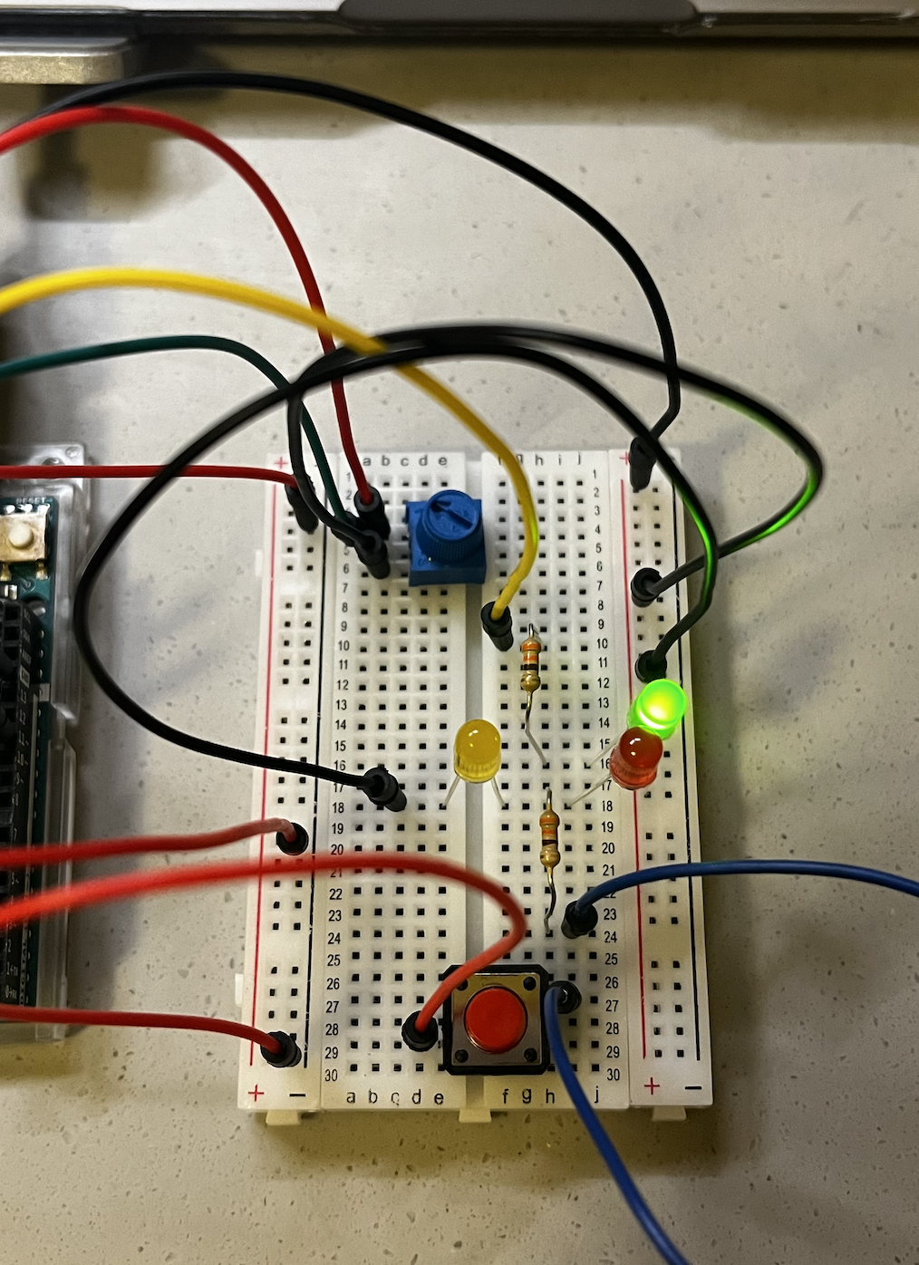
The concept of this assignment is traffic light. In the circuit, I used red, yellow, and green LEDs to mimic the traffic light. The red and yellow LED turns on when the button is pressed and off when the button is not pressed. The green light changes its dimness according to the potentiometer. Many drivers often wish the green light to be on for a long time so that they can drive continuously through the traffic lights. So I used the potentiometer to let the green LED stay on with full dimness when all of 5V is supplied.
Code & Sketch
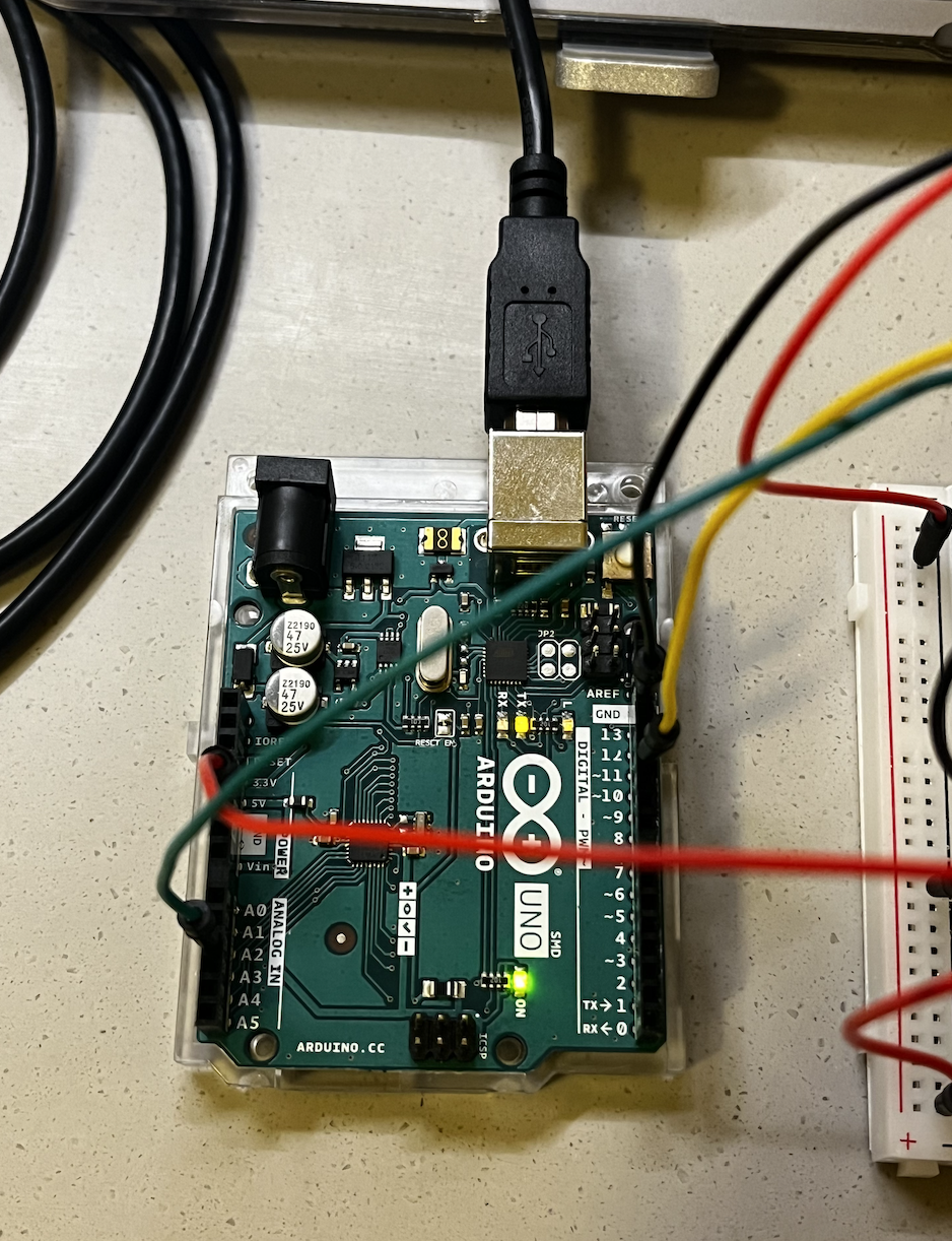
When creating the circuit, I focused on building the digital circuit first and then the analog circuit. In this way, I did not confuse myself and was able to make sure each component worked.
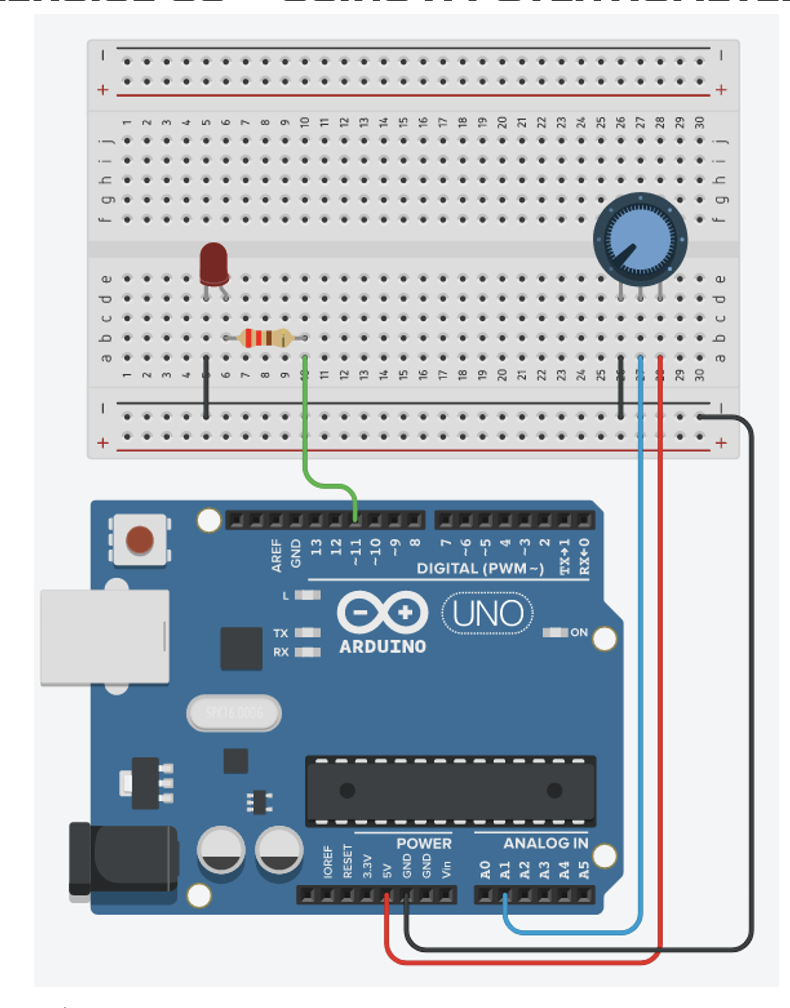
I referenced the design of the circuit for the potentiometer that I learned in class (the sketch is displayed below). Along with the design of the circuit for the potentiometer or the analog sensor, I used a very simple design for the button or the digital sensor. For both designs, I used a 330 ohm resistor because using a 10K ohm resistor was unnecessary.
Below is the code for the entire circuit. I only coded for the potentiometer because Arduino code was not needed to activate the button. The code for running the potentiometer is very simple. I initially defined a variable ‘led’ and used sensorValue to determine the brightness of the LED. I used PWM pin 11 to activate the brightness effect and delay to make the dimness effect visible.
int led = 11;

void setup() {

  Serial.begin(9600);

  //pin 11 output
  pinMode(led, OUTPUT);

}

void loop() {

  int sensorValue = analogRead(A2);
  Serial.println(sensorValue);

  // set the brightness of pin 11 according to the sensorValue and divided by 4
  analogWrite(led, sensorValue/4);

  // delay effect for 30 milliseconds to see the change in dimness
  delay(30);

}
Reflection
Creating the circuit was not difficult because most of it was materials covered in class. However, if I had to mention one slightly challenging thing, I would say it is working with tiny materials. My hand was comparatively larger than all the elements and trying to place them on the breadboard, I had to be careful to not misplace or interrupt the other elements already positioned on the breadboard.
To add on, when I first thought of this assignment, I wanted to have separate buttons for the red and yellow LEDs. However, due to the limited space on the breadboard, I was not able to do so. Therefore, for improvement, I would like to readjust the position of the elements on the breadboard so that I can fit one more button for the LED and be able to control the red and yellow LED separately.
Outcome