Design meets Disability | Creative Response | Week 12

This week’s reading talks about how design is important,  and sets a trend,  even in the medical field. The compare and contrast between different approaches to design in the case of eyewear, prosthetics, hearing aids etc was very interesting to me . I thought – is it just marketing that causes these differences or is it something at a much deeper level? The heading” good design on any terms ” compelled me to think about why this phrase was worth giving a thought. The example of Charles and Ray Eames making a leg splint that was ‘designed’ well illustrated this concept.

The discussion on fashion v/s discussion was intriguing too. The author shows how these two are not necessarily mutually exclusive as in the case of eyewear. He talks about a balance between simplicity and overly complex/colorful/designed things. One good example he gave that stuck to my mind is that of AirPods along with the quote “if I had more time, I would have written a shorter letter” which means that just because something is simple doesn’t mean that a lot of thought was not required into making it . \Infact,  genius can be found in simplicity.

I hope to embrace these concepts in my final project and design something user-friendly and simple .

Week 12 Reading – Shaikha AlKaabi

This week’s reading, “Design Meets Disability,” examines the relationship between design and disability, challenging the traditional view that disability aids should be discreet and practically invisible. The book argues for a new approach that balances functionality with aesthetic appeal, similar to how glasses have evolved from a medical necessity to a fashion statement. It emphasizes that disability aids should not only serve practical purposes but also make positive aesthetic statements.

The text highlights examples like the Eameses’ leg splints, initially designed for functionality but now celebrated for their innovative design. This shows the potential for disability design to extend beyond basic functionality and influence broader design disciplines.

The book critiques cultural and social norms that favor invisibility in disability aids and advocates for designs that are empowering and expressive. It explores how products like glasses have successfully become both functional and fashionable, suggesting a similar potential for other disability aids.

To conclude, “Design Meets Disability” calls for a reevaluation of design principles in the context of disability. It argues for designs that are not only functional but also aspirational and culturally relevant, aiming to reflect the diversity of users and contribute to a more inclusive society where design enhances individual identity and expression.

Week 12 Reading Response: Designing for Disability

Designs, designs, designs. Throughout our whole life everything we see was designed and adapted for us (humans) to be used in the most practical and (sometimes) efficient way. The thing is that, all of these things more often than note don’t take into account people with disabilities.

One of the problems for that, as mentioned in the reading, is that people with disabilities cannot be exactly grouped the same as an “average human”. What I mean by that is the design process for items used by people with disabilities needs to be more tailored individually, because these people, even though they might be diagnosed with the same type of disability, very often have different ways of experiencing the world and “fighting” through the disability.

On the bright side, recently, I have seen more applications and Programs/ Games which seamlessly incorporate designs which take these people into account. One example is the game Fortnite. Fortnite has a special menu in the Video Settings where you can change the colors based on the Persons Type and Level of daltonism. This changes all the colors on the screen and allows for the player to have a normal playing experience. Another feature this game has is the Sound circle, which is a circle which appears around the character displaying where sounds come from, so this takes people with hearing disabilities into account.

It has also been a pleasure to be a witness of an IM Project last semester from one of my friends. He made a small machine which would let users hear a word and then learn the Braille alphabet. I thought this was a very nice design, with small pads that mimic the little dots from the Alphabet.

I feel like in the future we need to contribute to the community even more by adding more designs which would further improve the life of people with disabilities. The change starts from US!


Reading Response 9 (Week 11)

“Design meets Disability” was an eye-opening exploration of the complex interplay between design, disability, and dignity. The notion that assistive devices can be both functional and stylish is a powerful one, breaking away from the traditional paradigm that prioritized hiding disabilities rather than celebrating them. As someone passionate about disability activism, it has been my personal mission to make society more accessible for people with disabilities. This reading thus prompted me to reconsider the traditional approaches to designing assistive technologies and encouraged me to explore more inclusive and culturally relevant design solutions. It also helped me ideate my final IM project- making a sign language glove, particularly through its emphasis on simplicity and cognitive accessibility reminding me of the importance of intuitive design in facilitating meaningful interactions and experiences for users with disabilities.


The discussion on the evolution of eyewear from medical necessity to fashion accessory was also intriguing, illustrating how incorporating fashion culture into design can lead to more positive perceptions of disability. I have used spectacles since the age of 5. I currently have high myopia (-11! yeah I know…). But I have never been insecure about wearing glasses or never considered laser eye surgery. Now that I look back, one of the reasons is because I enjoyed selecting new spectacles to wear every few years. I knew myopia is not something I could hide or change, so I coped with it by making it my style. Similarly, embracing fashion culture and aesthetics can transform the perception of other assistive devices, empowering individuals with disabilities to embrace their uniqueness rather than hide it.  Overall, this reading reinforced my commitment to creating inclusive and empowering solutions that celebrate diversity and promote social inclusion.

Assignment 12: Code – In class exercises

Exercise 1

For this exercise, we used a photosensor to control the x position of an ellipse in p5. The more light the photosensor reads, the further right the ellipse’s position is.

Demo:

https://intro.nyuadim.com/wp-content/uploads/2024/04/Exercise-1-Video.mov

Codes:

p5 –

let circlePosition = 100;
function setup() {
  createCanvas(400, 400);
  textSize(18);
  fill(243,213,205);
  text("Press the space bar to connect port", width / 2, 60);
}
function draw() {
  background(176, 16, 50);
  textSize(18);
  fill(243,213,205);
  text("Press the space bar to connect port", 60, 60);
  ellipse(circlePosition, height / 2, 70, 70);
}
// Function to set up the serial connection
function keyPressed() {
  if (key == " ") {
    setUpSerial();     
  }
}
// Function to read the data from serial port
function readSerial(data) {
  // Check if data received is not null
  if (data != null) {
    // Mapping the data to 0-400 and sets it as X position of the circle
    circlePosition = map(int(data), 0, 1023, 0, 400);
  }
}

Arduino –

void setup() {
  Serial.begin(9600); // Begin serial communication 
}
void loop() {
  int sensor = analogRead(A0);
  delay(5);
  Serial.println(sensor);
 
}

Circuit:

Exercise 2

For this exercise, we created a gradient on p5 that goes from green to black along the y-axis. When the mouse is on the highest point of the canvas, meaning at the greenest point, the LED is the brightest. The further the mouse goes down towards the black, the darker it gets.

Demo:

https://intro.nyuadim.com/wp-content/uploads/2024/04/IMG_2972.mov

Codes:

p5 –

function setup() {
  createCanvas(400, 400);
  textSize(20);
}

function draw() {
  // Gradient background from green to black
  setGradient(0, 0, width, height, color(0, 255, 0), color(0));


  if (!serialActive) {
    fill(255);
    text("Press space bar to select port", 60, 60);
  } else {
  }

  // Change brightness of LED based on mouse position
  let brightness = map(mouseY, 0, width, 255, 0);

  // Send the brightness value to Arduino
  if (serialActive) {
    let sendToArduino = brightness + "\n";
    writeSerial(sendToArduino);
  }
}

// Function to draw a gradient background
function setGradient(x, y, w, h, c1, c2) {
  noFill();
  for (let i = y; i <= y + h; i++) {
    let inter = map(i, y, y + h, 0, 1);
    let c = lerpColor(c1, c2, inter);
    stroke(c);
    line(x, i, x + w, i);
  }
}

// Function to begin serial connection
function keyPressed() {
  if (key == " ") {
    setUpSerial();
  }
}

function readSerial(data) {
  if (data != null) {
    serialActive = true;
  }
}

Arduino –

int ledPin = 9; 
int brightness = 0; 

void setup() {
  Serial.begin(9600);
  pinMode(LED_BUILTIN, OUTPUT);
  pinMode(ledPin, OUTPUT);
  digitalWrite(ledPin, LOW); // Starts with LED off
  while (!Serial) { // Wait for serial connection 
    delay(500);
  }
  Serial.println("Arduino initialized"); 
}

void loop() {
  if (Serial.available() > 0) {
    brightness = Serial.parseInt(); // Read brightness value
    analogWrite(ledPin, brightness);
    Serial.read(); 
  }
  digitalWrite(LED_BUILTIN, LOW); // LED off when there is no data
}

Circuit:

Exercise 3

For this exercise, we established bidirectional communication between the Arduino and the p5 sketch, enabling real-time interaction between physical input (potentiometer) and visual output (LED indication) synchronized with the simulation on p5.

The Arduino code reads data from a potentiometer connected to analog pin and sends it to the p5.js sketch. It also receives position data from the p5.js sketch via serial communication and controls an LED connected to pin 9 accordingly. The setup() function initializes serial communication and sets pin modes for the LED, potentiometer, and built-in LED. It initiates a handshake with the p5.js sketch by sending a starting message until it receives data from the serial port.

Demo:

Codes:

p5 –

let velocity;
let gravity;
let position;
let acceleration;
let breeze;
let drag = 0.99;
let mass = 50;
let heightOfBall = 0;
function setup() {
  createCanvas(640, 360);
 
  noFill();
  position = createVector(width/2, 0);
  velocity = createVector(0,0);
  acceleration = createVector(0,0);
  gravity = createVector(0, 0.5*mass);
  breeze = createVector(0,0); 
}
function draw() {
  background(215);
  fill(0);
  
  if (!serialActive) {
    text("Press space bar to connect Arduino", 50, 60);
  }
  else 
  {
  
  applyForce(breeze); 
  applyForce(gravity);
  velocity.add(acceleration);
  velocity.mult(drag);
  position.add(velocity);
  acceleration.mult(0);
  ellipse(position.x,position.y,mass,mass);
    
  if (position.y > height-mass/2) {
      velocity.y *= -0.9;  
    
      position.y = height-mass/2;
    
    heightOfBall = 0;
    
    } 
    else {
      heightOfBall = 1;
    }
  }
}
function applyForce(force){
  // Newton's 2nd law: F = M * A
  // or A = F / M
  let f = p5.Vector.div(force, mass);
  acceleration.add(f);
}
function keyPressed() {
  if (key == " ") {
    // important to have in order to start the serial connection!!
    setUpSerial();
  }   
  else if (key=='b'){
    mass=random(15,80);
    position.y=-mass;
    velocity.mult(0);
  }
}
// this callback function
function readSerial(data) {
    ////////////////////////////////////
    //READ FROM ARDUINO HERE
    ////////////////////////////////////
  
     if (data != null) {
    // make sure there is actually a message
    
    let fromArduino = split(trim(data), ",");
    
       // if the right length, then proceed
    if (fromArduino.length == 1) {
//sensor value is the input from potentiometer
      let sensorVal = int(fromArduino[0]);
      
//potentiometer value ranges from 0 - 1023
//for values less than 400,wind blows to right
      if (sensorVal < 400){
        breeze.x=1
      }
//if value between 400 and 500, wind stops so ball stops
      else if(sensorVal >= 400 && sensorVal < 500){
        breeze.x = 0
      }
//if value greater than 500, wind blows to left
      else {
        breeze.x = -1
      }
          //////////////////////////////////
          //SEND TO ARDUINO HERE (handshake)
          //////////////////////////////////
    }
//height of ball sent to arduino to check if ball on floor or not
    let sendToArduino = heightOfBall  + "\n";
    writeSerial(sendToArduino);
  }
}

Arduino –

const int poten_pin = A5;
const int ledPin = 9;
void setup() {
 Serial.begin(9600); // Start serial communication at 9600 bps
 pinMode(LED_BUILTIN, OUTPUT);
 pinMode(ledPin, OUTPUT);
 pinMode(poten_pin, INPUT);
 // start the handshake
 while (Serial.available() <= 0) {
   digitalWrite(LED_BUILTIN, HIGH); // on/blink while waiting for serial data
   Serial.println("0,0"); // send a starting message
   delay(300);            // wait 1/3 second
   digitalWrite(LED_BUILTIN, LOW);
   delay(50);
 }
}
void loop()
{
 // wait for data from p5 before doing something
   while (Serial.available())
   {
     digitalWrite(LED_BUILTIN, HIGH);
     digitalWrite(ledPin, LOW);
//read the position of ball from p5
     int position = Serial.parseInt();
  
     if (Serial.read() == '\n') {
       // Read potentiometer value
     int sensorValue = analogRead(poten_pin);
     //send value to p5
     Serial.println(sensorValue);
     }
//if ball is touching the ground i.e. height is zero, turn LED on
     if (position == 0)
     {
       digitalWrite(ledPin, HIGH);
     }
     else{
       digitalWrite(ledPin, LOW);
     }
   }
     digitalWrite(LED_BUILTIN, LOW);
   }

Circuit:

Assignment #12 – Code – ☆In-Class Exercises☆

Exercise 1

For this exercise, we used a photosensor to control the x position of an ellipse in p5. The more light the photosensor reads, the further right the ellipse’s position is.

Demo:

Exercise 1 Video

Codes:

p5 –

let circlePosition = 100;
function setup() {
  createCanvas(400, 400);
  textSize(18);
  fill(243,213,205);
  text("Press the space bar to connect port", width / 2, 60);
}
function draw() {
  background(176, 16, 50);
  textSize(18);
  fill(243,213,205);
  text("Press the space bar to connect port", 60, 60);
  ellipse(circlePosition, height / 2, 70, 70);
}
// Function to set up the serial connection
function keyPressed() {
  if (key == " ") {
    setUpSerial();     
  }
}
// Function to read the data from serial port
function readSerial(data) {
  // Check if data received is not null
  if (data != null) {
    // Mapping the data to 0-400 and sets it as X position of the circle
    circlePosition = map(int(data), 0, 1023, 0, 400);
  }
}

Arduino –

void setup() {
  Serial.begin(9600); // Begin serial communication 
}
void loop() {
  int sensor = analogRead(A0);
  delay(5);
  Serial.println(sensor);
 
}

Circuit:

Exercise 2

For this exercise, we created a gradient on p5 that goes from green to black along the y-axis. When the mouse is on the highest point of the canvas, meaning at the greenest point, the LED is the brightest. The further the mouse goes down towards the black, the darker it gets.

Demo:

IMG_2972

Codes:

p5 –

function setup() {
  createCanvas(400, 400);
  textSize(20);
}

function draw() {
  // Gradient background from green to black
  setGradient(0, 0, width, height, color(0, 255, 0), color(0));


  if (!serialActive) {
    fill(255);
    text("Press space bar to select port", 60, 60);
  } else {
  }

  // Change brightness of LED based on mouse position
  let brightness = map(mouseY, 0, width, 255, 0);

  // Send the brightness value to Arduino
  if (serialActive) {
    let sendToArduino = brightness + "\n";
    writeSerial(sendToArduino);
  }
}

// Function to draw a gradient background
function setGradient(x, y, w, h, c1, c2) {
  noFill();
  for (let i = y; i <= y + h; i++) {
    let inter = map(i, y, y + h, 0, 1);
    let c = lerpColor(c1, c2, inter);
    stroke(c);
    line(x, i, x + w, i);
  }
}

// Function to begin serial connection
function keyPressed() {
  if (key == " ") {
    setUpSerial();
  }
}

function readSerial(data) {
  if (data != null) {
    serialActive = true;
  }
}

Arduino –

int ledPin = 9; 
int brightness = 0; 

void setup() {
  Serial.begin(9600);
  pinMode(LED_BUILTIN, OUTPUT);
  pinMode(ledPin, OUTPUT);
  digitalWrite(ledPin, LOW); // Starts with LED off
  while (!Serial) { // Wait for serial connection 
    delay(500);
  }
  Serial.println("Arduino initialized"); 
}

void loop() {
  if (Serial.available() > 0) {
    brightness = Serial.parseInt(); // Read brightness value
    analogWrite(ledPin, brightness);
    Serial.read(); 
  }
  digitalWrite(LED_BUILTIN, LOW); // LED off when there is no data
}

Circuit:


Exercise 3

For this exercise, we established bidirectional communication between the Arduino and the p5 sketch, enabling real-time interaction between physical input (potentiometer) and visual output (LED indication) synchronized with the simulation on p5.

The Arduino code reads data from a potentiometer connected to analog pin and sends it to the p5.js sketch. It also receives position data from the p5.js sketch via serial communication and controls an LED connected to pin 9 accordingly. The setup() function initializes serial communication and sets pin modes for the LED, potentiometer, and built-in LED. It initiates a handshake with the p5.js sketch by sending a starting message until it receives data from the serial port.

Demo:

Codes:

p5 –

let velocity;
let gravity;
let position;
let acceleration;
let breeze;
let drag = 0.99;
let mass = 50;
let heightOfBall = 0;
function setup() {
  createCanvas(640, 360);
 
  noFill();
  position = createVector(width/2, 0);
  velocity = createVector(0,0);
  acceleration = createVector(0,0);
  gravity = createVector(0, 0.5*mass);
  breeze = createVector(0,0); 
}
function draw() {
  background(215);
  fill(0);
  
  if (!serialActive) {
    text("Press space bar to connect Arduino", 50, 60);
  }
  else 
  {
  
  applyForce(breeze); 
  applyForce(gravity);
  velocity.add(acceleration);
  velocity.mult(drag);
  position.add(velocity);
  acceleration.mult(0);
  ellipse(position.x,position.y,mass,mass);
    
  if (position.y > height-mass/2) {
      velocity.y *= -0.9;  
    
      position.y = height-mass/2;
    
    heightOfBall = 0;
    
    } 
    else {
      heightOfBall = 1;
    }
  }
}
function applyForce(force){
  // Newton's 2nd law: F = M * A
  // or A = F / M
  let f = p5.Vector.div(force, mass);
  acceleration.add(f);
}
function keyPressed() {
  if (key == " ") {
    // important to have in order to start the serial connection!!
    setUpSerial();
  }   
  else if (key=='b'){
    mass=random(15,80);
    position.y=-mass;
    velocity.mult(0);
  }
}
// this callback function
function readSerial(data) {
    ////////////////////////////////////
    //READ FROM ARDUINO HERE
    ////////////////////////////////////
  
     if (data != null) {
    // make sure there is actually a message
    
    let fromArduino = split(trim(data), ",");
    
       // if the right length, then proceed
    if (fromArduino.length == 1) {
//sensor value is the input from potentiometer
      let sensorVal = int(fromArduino[0]);
      
//potentiometer value ranges from 0 - 1023
//for values less than 400,wind blows to right
      if (sensorVal < 400){
        breeze.x=1
      }
//if value between 400 and 500, wind stops so ball stops
      else if(sensorVal >= 400 && sensorVal < 500){
        breeze.x = 0
      }
//if value greater than 500, wind blows to left
      else {
        breeze.x = -1
      }
          //////////////////////////////////
          //SEND TO ARDUINO HERE (handshake)
          //////////////////////////////////
    }
//height of ball sent to arduino to check if ball on floor or not
    let sendToArduino = heightOfBall  + "\n";
    writeSerial(sendToArduino);
  }
}

Arduino –

const int poten_pin = A5;
const int ledPin = 9;
void setup() {
 Serial.begin(9600); // Start serial communication at 9600 bps
 pinMode(LED_BUILTIN, OUTPUT);
 pinMode(ledPin, OUTPUT);
 pinMode(poten_pin, INPUT);
 // start the handshake
 while (Serial.available() <= 0) {
   digitalWrite(LED_BUILTIN, HIGH); // on/blink while waiting for serial data
   Serial.println("0,0"); // send a starting message
   delay(300);            // wait 1/3 second
   digitalWrite(LED_BUILTIN, LOW);
   delay(50);
 }
}
void loop()
{
 // wait for data from p5 before doing something
   while (Serial.available())
   {
     digitalWrite(LED_BUILTIN, HIGH);
     digitalWrite(ledPin, LOW);
//read the position of ball from p5
     int position = Serial.parseInt();
  
     if (Serial.read() == '\n') {
       // Read potentiometer value
     int sensorValue = analogRead(poten_pin);
     //send value to p5
     Serial.println(sensorValue);
     }
//if ball is touching the ground i.e. height is zero, turn LED on
     if (position == 0)
     {
       digitalWrite(ledPin, HIGH);
     }
     else{
       digitalWrite(ledPin, LOW);
     }
   }
     digitalWrite(LED_BUILTIN, LOW);
   }

Circuit:

Week 12: Design meets disability

“Design Meets Disability” by Graham Pullin provides a thought-provoking exploration of the potential symbiotic relationship between design and disability. Pullin challenges the traditional separation between assistive devices and mainstream design by questioning why certain products, such as eyeglasses, have undergone a transformation into fashionable items while others, like hearing aids or prosthetic limbs, remain largely utilitarian. This critique exposes a broader issue within design culture—the tendency to prioritize aesthetics and marketability over functionality and inclusivity.

However, while Pullin’s argument for integrating disability considerations into mainstream design is compelling, it also raises questions about the motivations behind such integration. Is the goal to genuinely enhance the lives of disabled individuals by providing them with more aesthetically pleasing and user-friendly products, or is it driven primarily by profit and market trends? Furthermore, there is a risk of superficiality in simply “fashionizing” assistive devices without addressing deeper systemic issues such as accessibility, affordability, and social stigma. Hence, while Pullin’s exploration of the intersection of design and disability is interesting, it also invites critical reflection on the broader societal implications of such integration.

Week 12 Assignment – Rashed and Jana

Exercise 1: 

P5 code:

let rVal = 0;
let alpha = 255;
let left = 0; // True (1) if mouse is being clicked on left side of screen
let right = 0; // True (1) if mouse is being clicked on right side of screen

function setup() {
createCanvas(640, 480);
textSize(18);
}

function draw() {
// one value from Arduino controls the background's red color
background(255)

// the other value controls the text's transparency value
fill(255, 0,0)

if (!serialActive) {
text("Press Space Bar to select Serial Port", 20, 30);
} else {
text("Connected", 20, 30);
// Print the current values
text('rVal = ' + str(rVal), 20, 50);
text('alpha = ' + str(alpha), 20, 70);
}

// click on one side of the screen, one LED will light up
// click on the other side, the other LED will light up
if (mouseIsPressed) {
if (mouseX > rVal-50 && mouseX < rVal+50 && mouseY > height/2-50 && mouseY < height/2+50) {
right = 1;
}
} else {
right = 0;
}
ellipse(rVal, height/2, 50,50)
}

function keyPressed() {
if (key == " ") {
// important to have in order to start the serial connection!!
setUpSerial();
}
}

// This function will be called by the web-serial library
// with each new line of data. The serial library reads
// the data until the newline and then gives it to us through
// this callback function
function readSerial(data) {
////////////////////////////////////
//READ FROM ARDUINO HERE
////////////////////////////////////

if (data != null) {
// make sure there is actually a message
// split the message
let fromArduino = split(trim(data), ",");
// if the right length, then proceed
if (fromArduino.length == 2) {
// only store values here
// do everything with those values in the main draw loop

// We take the string we get from Arduino and explicitly
// convert it to a number by using int()
// e.g. "103" becomes 103
rVal = int(fromArduino[0]);
alpha = int(fromArduino[1]);
}

//////////////////////////////////
//SEND TO ARDUINO HERE (handshake)
//////////////////////////////////
let sendToArduino = left + "," + right + "\n";
writeSerial(sendToArduino);
}
}


We did not face any big issue in this part. We just added the ellipse and changed its position to rVal, height/2.

Video:

Exercise 2: 

P5 code:

let rVal = 0;
let alpha = 255;
let left = 0; // True (1) if mouse is being clicked on left side of screen
let right = 0; // True (1) if mouse is being clicked on right side of screen

function setup() {
createCanvas(640, 480);
textSize(18);
}

function draw() {
// one value from Arduino controls the background's red color
background(map(rVal, 0, 1023, 0, 255), 255, 200);

// the other value controls the text's transparency value
fill(255, 0, 255, map(alpha, 0, 1023, 0, 255));

if (!serialActive) {
text("Press Space Bar to select Serial Port", 20, 30);
} else {
text("Connected", 20, 30);
// Print the current values
text('rVal = ' + str(rVal), 20, 50);
text('alpha = ' + str(alpha), 20, 70);
}


function keyPressed() //built in function
{
if (key == " ") //if space is pressed then
{
setUpSerial(); //setup the serial.
}
else if (keyCode == DOWN_ARROW)
{
if (right != 0)
{
right = right - 20;
}
}
else if (keyCode == UP_ARROW)
{
if (right != 250)
{
right = right + 20;
}
}
}
}

// This function will be called by the web-serial library
// with each new *line* of data. The serial library reads
// the data until the newline and then gives it to us through
// this callback function
function readSerial(data) {
////////////////////////////////////
//READ FROM ARDUINO HERE
////////////////////////////////////

if (data != null) {
// make sure there is actually a message
// split the message
let fromArduino = split(trim(data), ",");
// if the right length, then proceed
if (fromArduino.length == 2) {
// only store values here
// do everything with those values in the main draw loop

// We take the string we get from Arduino and explicitly
// convert it to a number by using int()
// e.g. "103" becomes 103
rVal = int(fromArduino[0]);
alpha = int(fromArduino[1]);
}

//////////////////////////////////
//SEND TO ARDUINO HERE (handshake)
//////////////////////////////////
let sendToArduino = left + "," + right + "\n";
writeSerial(sendToArduino);
}
}


Arduino code for Exercise 1 and 2:

int leftLedPin = 2;
int rightLedPin = 5;

void setup() {
// Start serial communication so we can send data
// over the USB connection to our p5js sketch
Serial.begin(9600);

// We'll use the builtin LED as a status output.
// We can't use the serial monitor since the serial connection is
// used to communicate to p5js and only one application on the computer
// can use a serial port at once.
pinMode(LED_BUILTIN, OUTPUT);

// Outputs on these pins
pinMode(leftLedPin, OUTPUT);
pinMode(rightLedPin, OUTPUT);

// Blink them so we can check the wiring
digitalWrite(leftLedPin, HIGH);
digitalWrite(rightLedPin, HIGH);
delay(200);
digitalWrite(leftLedPin, LOW);
digitalWrite(rightLedPin, LOW);


// start the handshake
while (Serial.available() <= 0) {
digitalWrite(LED_BUILTIN, HIGH); // on/blink while waiting for serial data
Serial.println("0,0"); // send a starting message
delay(300); // wait 1/3 second
digitalWrite(LED_BUILTIN, LOW);
delay(50);
}
}

void loop() {
// wait for data from p5 before doing something
while (Serial.available()) {
digitalWrite(LED_BUILTIN, HIGH); // led on while receiving data

int left = Serial.parseInt();
int right = Serial.parseInt();
if (Serial.read() == '\n') {
digitalWrite(leftLedPin, left);
digitalWrite(rightLedPin, right);
int sensor = analogRead(A0);
delay(5);
int sensor2 = analogRead(A1);
delay(5);
Serial.print(sensor);
Serial.print(',');
Serial.println(sensor2);
}
}
digitalWrite(LED_BUILTIN, LOW);
}


Challenges:

We tried to get the light to decrease its brightness every time the person would click on the left side of the screen and for the brightness to increase whenever the person clicks on the right side of the screen. The code was correct, but for some reason it was not working. So, it might be something with the bulb or the Arduino itself. However, the light does take around 4 clicks on both sides of the screen to turn off or on so, we would consider that a success.

Video:

Exercise 3: 

P5 code:

let dragForce = 0.99;
let mass = 20;
let ledState = 0;
let velocity;
let gravity;
let position;
let acceleration;
let wind;
let force;
let bounced = false;


function setup() {
createCanvas(640, 480);
textSize(18);
position = createVector(width / 2, 0);
velocity = createVector(0, 0);
acceleration = createVector(0, 0);
gravity = createVector(0, 0.3 * mass);
wind = createVector(0, 0);
}

function draw() {

background(255);

if (!serialActive) {
text("Press Space Bar to select Serial Port", 20, 30);
} else {
text("Connected", 20, 30);

noStroke();
force = p5.Vector.div(wind, mass);
acceleration.add(force);
force = 0;
force = p5.Vector.div(gravity, mass);
acceleration.add(force);
force = 0;
velocity.add(acceleration);
velocity.mult(dragForce);
position.add(velocity);
acceleration.mult(0);

ellipse(position.x, position.y, mass, mass);
if (position.y > (height - mass / 2)-30 ) {
velocity.y *= -0.9;
position.y = (height - mass / 2)-30;
ledState= 1;

if (!bounced) {
fill('blue'); // Red when just bounced
bounced = true; // Update bounce state
} else {
fill('red'); // White otherwise
bounced = false; // Reset bounce state
}
} else {
ledState = 0;
}


}

rect(0,height-30,width,30);

}

function keyPressed() {
if (key == " ") {
// important to have in order to start the serial connection!!
setUpSerial();
}
}
function readSerial(data) {
if (data != null) {
// make sure there is actually a message
// split the message
let fromArduino = split(trim(data), ",");
// if the right length, then proceed
if (fromArduino.length == 1) {
let windCurrent = int(fromArduino[0]);
wind.x = map(windCurrent, 0, 1023, -1, 1);
}

//////////////////////////////////
//SEND TO ARDUINO HERE (handshake)
//////////////////////////////////
let sendToArduino = ledState + "\n";
writeSerial(sendToArduino);
}
}


Arduino code:

int ledPin = 10;
int potPin = A0;

void setup() {
Serial.begin(9600);

pinMode(LED_BUILTIN, OUTPUT);

// Outputs on these pins
pinMode(ledPin, OUTPUT);

// start the handshake
while (Serial.available() <= 0) {
digitalWrite(LED_BUILTIN, HIGH); // on/blink while waiting for serial data
Serial.println("0"); // send a starting message
delay(300); // wait 1/3 second
digitalWrite(LED_BUILTIN, LOW);
delay(50);
}
}

void loop() {
// wait for data from p5 before doing something
while (Serial.available()) {
digitalWrite(LED_BUILTIN, HIGH); // led on while receiving data

int right = Serial.parseInt();
if (Serial.read() == '\n') {
digitalWrite(ledPin, right);
int potValue = analogRead(potPin);
delay(5);
Serial.println(potValue);
}
}
}


Challenges:

Everything went smoothly when writing the code. However, when we would click the play button to see the sketch, it would give us the error: “setUpArduino is not defined”. So, we spent countless minutes searching for something that was not there. After looking at the professors week 12 example on serial connection, we realized that we have forgotten the tab that would connect P5 to Arduino. So we just added that and it worked.

Video:

very very cute :3

Week 12 Assignment – Jana and Rashed

Exercise 1: 

P5 code:

let rVal = 0;
let alpha = 255;
let left = 0; // True (1) if mouse is being clicked on left side of screen
let right = 0; // True (1) if mouse is being clicked on right side of screen

function setup() {
  createCanvas(640, 480);
  textSize(18);
}

function draw() {
  // one value from Arduino controls the background's red color
  background(255)

  // the other value controls the text's transparency value
  fill(255, 0,0)

  if (!serialActive) {
    text("Press Space Bar to select Serial Port", 20, 30);
  } else {
    text("Connected", 20, 30);
    // Print the current values
    text('rVal = ' + str(rVal), 20, 50);
    text('alpha = ' + str(alpha), 20, 70);
  }

  // click on one side of the screen, one LED will light up
  // click on the other side, the other LED will light up
  if (mouseIsPressed) {
    if (mouseX > rVal-50 && mouseX < rVal+50 && mouseY > height/2-50 && mouseY < height/2+50) {
      right = 1;
    } 
  } else {
    right = 0;
  }
  ellipse(rVal, height/2, 50,50)
}

function keyPressed() {
  if (key == " ") {
    // important to have in order to start the serial connection!!
    setUpSerial();
  }
}

// This function will be called by the web-serial library
// with each new line of data. The serial library reads
// the data until the newline and then gives it to us through
// this callback function
function readSerial(data) {
  ////////////////////////////////////
  //READ FROM ARDUINO HERE
  ////////////////////////////////////

  if (data != null) {
    // make sure there is actually a message
    // split the message
    let fromArduino = split(trim(data), ",");
    // if the right length, then proceed
    if (fromArduino.length == 2) {
      // only store values here
      // do everything with those values in the main draw loop
      
      // We take the string we get from Arduino and explicitly
      // convert it to a number by using int()
      // e.g. "103" becomes 103
      rVal = int(fromArduino[0]);
      alpha = int(fromArduino[1]);
    }

    //////////////////////////////////
    //SEND TO ARDUINO HERE (handshake)
    //////////////////////////////////
    let sendToArduino = left + "," + right + "\n";
    writeSerial(sendToArduino);
  }
}

We did not face any big issue in this part. We just added the ellipse and changed its position to rVal, height/2.

Video:

Exercise 2: 

P5 code:

let rVal = 0;
let alpha = 255;
let left = 0; // True (1) if mouse is being clicked on left side of screen
let right = 0; // True (1) if mouse is being clicked on right side of screen

function setup() {
  createCanvas(640, 480);
  textSize(18);
}

function draw() {
  // one value from Arduino controls the background's red color
  background(map(rVal, 0, 1023, 0, 255), 255, 200);

  // the other value controls the text's transparency value
  fill(255, 0, 255, map(alpha, 0, 1023, 0, 255));

  if (!serialActive) {
    text("Press Space Bar to select Serial Port", 20, 30);
  } else {
    text("Connected", 20, 30);
    // Print the current values
    text('rVal = ' + str(rVal), 20, 50);
    text('alpha = ' + str(alpha), 20, 70);
  }


function keyPressed() //built in function
{
  if (key == " ") //if space is pressed then
  {
    setUpSerial(); //setup the serial. 
  }
  else if (keyCode == DOWN_ARROW)
  {
    if (right != 0)
    {
      right = right - 20;
    }
  }
  else if (keyCode == UP_ARROW)
  {
    if (right != 250)
    {
      right = right + 20;
    }
  }
}
  }

// This function will be called by the web-serial library
// with each new *line* of data. The serial library reads
// the data until the newline and then gives it to us through
// this callback function
function readSerial(data) {
  ////////////////////////////////////
  //READ FROM ARDUINO HERE
  ////////////////////////////////////

  if (data != null) {
    // make sure there is actually a message
    // split the message
    let fromArduino = split(trim(data), ",");
    // if the right length, then proceed
    if (fromArduino.length == 2) {
      // only store values here
      // do everything with those values in the main draw loop
      
      // We take the string we get from Arduino and explicitly
      // convert it to a number by using int()
      // e.g. "103" becomes 103
      rVal = int(fromArduino[0]);
      alpha = int(fromArduino[1]);
    }

    //////////////////////////////////
    //SEND TO ARDUINO HERE (handshake)
    //////////////////////////////////
    let sendToArduino = left + "," + right + "\n";
    writeSerial(sendToArduino);
  }
}

Arduino code for Exercise 1 and 2:

int leftLedPin = 2;
int rightLedPin = 5;

void setup() {
  // Start serial communication so we can send data
  // over the USB connection to our p5js sketch
  Serial.begin(9600);

  // We'll use the builtin LED as a status output.
  // We can't use the serial monitor since the serial connection is
  // used to communicate to p5js and only one application on the computer
  // can use a serial port at once.
  pinMode(LED_BUILTIN, OUTPUT);

  // Outputs on these pins
  pinMode(leftLedPin, OUTPUT);
  pinMode(rightLedPin, OUTPUT);

  // Blink them so we can check the wiring
  digitalWrite(leftLedPin, HIGH);
  digitalWrite(rightLedPin, HIGH);
  delay(200);
  digitalWrite(leftLedPin, LOW);
  digitalWrite(rightLedPin, LOW);


  // start the handshake
  while (Serial.available() <= 0) {
    digitalWrite(LED_BUILTIN, HIGH); // on/blink while waiting for serial data
    Serial.println("0,0"); // send a starting message
    delay(300);            // wait 1/3 second
    digitalWrite(LED_BUILTIN, LOW);
    delay(50);
  }
}

void loop() {
  // wait for data from p5 before doing something
  while (Serial.available()) {
    digitalWrite(LED_BUILTIN, HIGH); // led on while receiving data

    int left = Serial.parseInt();
    int right = Serial.parseInt();
    if (Serial.read() == '\n') {
      digitalWrite(leftLedPin, left);
      digitalWrite(rightLedPin, right);
      int sensor = analogRead(A0);
      delay(5);
      int sensor2 = analogRead(A1);
      delay(5);
      Serial.print(sensor);
      Serial.print(',');
      Serial.println(sensor2);
    }
  }
  digitalWrite(LED_BUILTIN, LOW);
}

Challenges:

We tried to get the light to decrease its brightness every time the person would click on the left side of the screen and for the brightness to increase whenever the person clicks on the right side of the screen. The code was correct, but for some reason it was not working. So, it might be something with the bulb or the Arduino itself. However, the light does take around 4 clicks on both sides of the screen to turn off or on so, we would consider that a success.

Video:

Exercise 3: 

P5 code:

let dragForce = 0.99;
let mass = 20;
let ledState = 0;
let velocity;
let gravity;
let position;
let acceleration;
let wind;
let force;
let bounced = false;


function setup() {
  createCanvas(640, 480);
  textSize(18);
  position = createVector(width / 2, 0);
  velocity = createVector(0, 0);
  acceleration = createVector(0, 0);
  gravity = createVector(0, 0.3 * mass);
  wind = createVector(0, 0);
}

function draw() {
  
  background(255);

  if (!serialActive) {
    text("Press Space Bar to select Serial Port", 20, 30);
  } else {
    text("Connected", 20, 30);

    noStroke();
    force = p5.Vector.div(wind, mass);
    acceleration.add(force);
    force = 0;
    force = p5.Vector.div(gravity, mass);
    acceleration.add(force);
    force = 0;
    velocity.add(acceleration);
    velocity.mult(dragForce);
    position.add(velocity);
    acceleration.mult(0);

    ellipse(position.x, position.y, mass, mass);
    if (position.y > (height - mass / 2)-30 ) {
      velocity.y *= -0.9;
      position.y = (height - mass / 2)-30;
      ledState= 1;
      
      if (!bounced) {
        fill('blue'); // Red when just bounced
        bounced = true; // Update bounce state
      } else {
        fill('red'); // White otherwise
        bounced = false; // Reset bounce state
      }
    } else {
      ledState = 0;
    }
  
    
  }

  rect(0,height-30,width,30);
  
}

function keyPressed() {
  if (key == " ") {
    // important to have in order to start the serial connection!!
    setUpSerial();
  }
}
function readSerial(data) {
  if (data != null) {
    // make sure there is actually a message
    // split the message
    let fromArduino = split(trim(data), ",");
    // if the right length, then proceed
    if (fromArduino.length == 1) {
      let windCurrent = int(fromArduino[0]);
      wind.x = map(windCurrent, 0, 1023, -1, 1);
    }

    //////////////////////////////////
    //SEND TO ARDUINO HERE (handshake)
    //////////////////////////////////
    let sendToArduino = ledState + "\n";
    writeSerial(sendToArduino);
  }
}

Arduino code:

int ledPin = 10;
int potPin = A0;

void setup() {
  Serial.begin(9600);

  pinMode(LED_BUILTIN, OUTPUT);

  // Outputs on these pins
  pinMode(ledPin, OUTPUT);

  // start the handshake
  while (Serial.available() <= 0) {
    digitalWrite(LED_BUILTIN, HIGH); // on/blink while waiting for serial data
    Serial.println("0"); // send a starting message
    delay(300);            // wait 1/3 second
    digitalWrite(LED_BUILTIN, LOW);
    delay(50);
  }
}

void loop() {
  // wait for data from p5 before doing something
  while (Serial.available()) {
    digitalWrite(LED_BUILTIN, HIGH); // led on while receiving data

    int right = Serial.parseInt();
    if (Serial.read() == '\n') {
      digitalWrite(ledPin, right);
      int potValue = analogRead(potPin);
      delay(5);
      Serial.println(potValue);
    }
  }
}

Challenges:

Everything went smoothly when writing the code. However, when we would click the play button to see the sketch, it would give us the error: “setUpArduino is not defined”. So, we spent countless minutes searching for something that was not there. After looking at the professors week 12 example on serial connection, we realized that we have forgotten the tab that would connect P5 to Arduino. So we just added that and it worked.

Video:

very very cute :3


Assignment | Week 12

 EXERCISE 01: ARDUINO TO P5 COMMUNICATION

The task was to make something that uses only one sensor on arduino and makes the ellipse in p5 move on the
horizontal axis, in the middle of the screen, and nothing on arduino is controlled by p5.

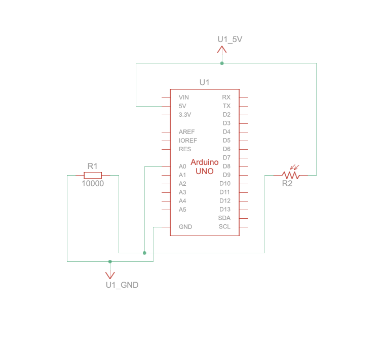
We utilized a simple set-up consisting of a potentiometer. We mapped its values to the x-position of the ellipse on p5. The ellipse moves across the x-axis as the potentiometer is turned.

Arduino Code:
void setup() {
  Serial.begin(9600); // Initialize serial communication at 9600 baud rate
}

void loop() {
  int sensorValue = analogRead(A0); // Read the value from the potentiometer
  Serial.println(sensorValue);      // Send the value to the serial port followed by a newline character
  delay(50);                        // Delay to prevent overwhelming the serial buffer
}
P5 Sketch:
let rVal = 0;
let alpha = 255;


function setup() {
  createCanvas(640, 480);
  textSize(18);
}

function draw() {

  background(255);
  if (!serialActive) {
    text("Press Space Bar to select Serial Port", 20, 30);
  } else {
    // Print the current values
    text('Potentiometer Value = ' + str(rVal), 20, 50);
    //text('alpha = ' + str(alpha), 20, 70);
  }
  let xpos = map(rVal, 0, 1023, 0, width);  // Map the sensor value to the canvas width
  ellipse(xpos, height / 2, 50, 50);  // Draw an ellipse at the mapped position
  
}

function keyPressed() {
  if (key == " ") {
    // important to have in order to start the serial connection!!
    setUpSerial();
  }
}
function readSerial(data) {
  ////////////////////////////////////
  //READ FROM ARDUINO HERE
  ////////////////////////////////////

  if (data != null) {
   
    let fromArduino = split(trim(data), ",");
    // if the right length, then proceed
    if (fromArduino.length == 1) {
      
      rVal = int(fromArduino[0]);
      
    }

   
  }
}

EXERCISE 02: P5 TO ARDUINO COMMUNICATION

Make something that controls the LED brightness from p5.

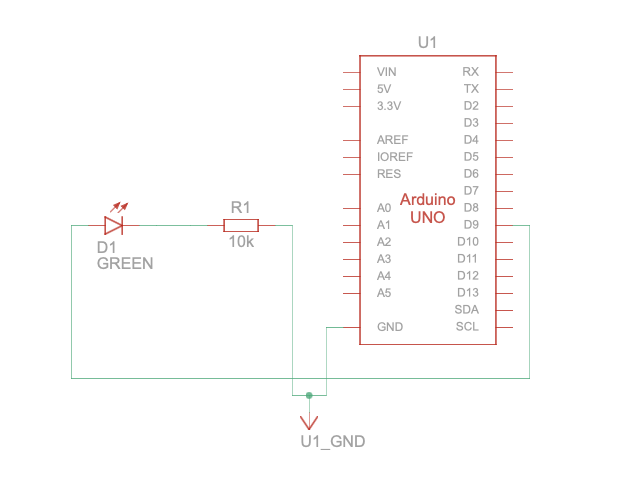
We used a slider in p5 and connected the led to a PWM pin. The slider controls the brightness level of the LED.

Arduino Code:
//Arduino Code

// Week 11.2 Example of bidirectional serial communication

// Inputs:
// - A0 - sensor connected as voltage divider (e.g. potentiometer or light sensor)
// - A1 - sensor connected as voltage divider 
//
// Outputs:
// - 2 - LED
// - 5 - LED

int leftLedPin = 10;
int rightLedPin = 5;

void setup() {
  // Start serial communication so we can send data
  // over the USB connection to our p5js sketch
  Serial.begin(9600);

  // We'll use the builtin LED as a status output.
  // We can't use the serial monitor since the serial connection is
  // used to communicate to p5js and only one application on the computer
  // can use a serial port at once.
  pinMode(LED_BUILTIN, OUTPUT);

  // Outputs on these pins
  pinMode(leftLedPin, OUTPUT);
  pinMode(rightLedPin, OUTPUT);

  // Blink them so we can check the wiring
  digitalWrite(leftLedPin, HIGH);
  digitalWrite(rightLedPin, HIGH);
  delay(200);
  digitalWrite(leftLedPin, LOW);
  digitalWrite(rightLedPin, LOW);


  // start the handshake
  while (Serial.available() <= 0) {
    digitalWrite(LED_BUILTIN, HIGH); // on/blink while waiting for serial data
    Serial.println("0,0"); // send a starting message
    delay(300);            // wait 1/3 second
    digitalWrite(LED_BUILTIN, LOW);
    delay(50);
  }
}

void loop() {
  // wait for data from p5 before doing something
  while (Serial.available()) {
    digitalWrite(LED_BUILTIN, HIGH); // led on while receiving data

    int left = Serial.parseInt();
    int right = Serial.parseInt();
    if (Serial.read() == '\n') {
      analogWrite(leftLedPin, left);
      digitalWrite(rightLedPin, right);
      int sensor = analogRead(A0);
      delay(5);
      int sensor2 = analogRead(A1);
      delay(5);
      Serial.print(sensor);
      Serial.print(',');
      Serial.println(sensor2);
    }
  }
  digitalWrite(LED_BUILTIN, LOW);
}
P5 Sketch:

Code:
let rVal = 0;
let alpha = 255;
let left = 0; // True (1) if mouse is being clicked on left side of screen
let right = 0; // True (1) if mouse is being clicked on right side of screen

function setup() {
  createCanvas(640, 480);
  textSize(18);
  ledSlider = createSlider(0, 255, 0);
  ledSlider.position(10, 40);
  ledSlider.style('width', '200px');
}

function draw() {
  // one value from Arduino controls the background's red color
  //background(map(rVal, 0, 1023, 0, 255), 255, 200);
  background('white');

  // the other value controls the text's transparency value
  fill('black');

  if (!serialActive) {
    text("Press Space Bar to select Serial Port", 20, 30);
  } else {
    text("Connected", 20, 30);
    // Print the current values
    //text('rVal = ' + str(rVal), 20, 50);
    //text('alpha = ' + str(alpha), 20, 70);
  }

  left = ledSlider.value();
  console.log(left);
  right = 0;
  // click on one side of the screen, one LED will light up
  // click on the other side, the other LED will light up
 
}

function keyPressed() {
  if (key == " ") {
    // important to have in order to start the serial connection!!
    setUpSerial();
  }
}

// This function will be called by the web-serial library
// with each new *line* of data. The serial library reads
// the data until the newline and then gives it to us through
// this callback function
function readSerial(data) {
  ////////////////////////////////////
  //READ FROM ARDUINO HERE
  ////////////////////////////////////

  if (data != null) {
    // make sure there is actually a message
    // split the message
    let fromArduino = split(trim(data), ",");
    // if the right length, then proceed
    if (fromArduino.length == 2) {
      // only store values here
      // do everything with those values in the main draw loop
      
      // We take the string we get from Arduino and explicitly
      // convert it to a number by using int()
      // e.g. "103" becomes 103
      rVal = int(fromArduino[0]);
      alpha = int(fromArduino[1]);
    }

    //////////////////////////////////
    //SEND TO ARDUINO HERE (handshake)
    //////////////////////////////////
    let sendToArduino = left + "," + right + "\n";
    writeSerial(sendToArduino);
  }
}


//Arduino Code
/*
// Week 11.2 Example of bidirectional serial communication

// Inputs:
// - A0 - sensor connected as voltage divider (e.g. potentiometer or light sensor)
// - A1 - sensor connected as voltage divider 
//
// Outputs:
// - 2 - LED
// - 5 - LED

int leftLedPin = 2;
int rightLedPin = 5;

void setup() {
  // Start serial communication so we can send data
  // over the USB connection to our p5js sketch
  Serial.begin(9600);

  // We'll use the builtin LED as a status output.
  // We can't use the serial monitor since the serial connection is
  // used to communicate to p5js and only one application on the computer
  // can use a serial port at once.
  pinMode(LED_BUILTIN, OUTPUT);

  // Outputs on these pins
  pinMode(leftLedPin, OUTPUT);
  pinMode(rightLedPin, OUTPUT);

  // Blink them so we can check the wiring
  digitalWrite(leftLedPin, HIGH);
  digitalWrite(rightLedPin, HIGH);
  delay(200);
  digitalWrite(leftLedPin, LOW);
  digitalWrite(rightLedPin, LOW);


  // start the handshake
  while (Serial.available() <= 0) {
    digitalWrite(LED_BUILTIN, HIGH); // on/blink while waiting for serial data
    Serial.println("0,0"); // send a starting message
    delay(300);            // wait 1/3 second
    digitalWrite(LED_BUILTIN, LOW);
    delay(50);
  }
}

void loop() {
  // wait for data from p5 before doing something
  while (Serial.available()) {
    digitalWrite(LED_BUILTIN, HIGH); // led on while receiving data

    int left = Serial.parseInt();
    int right = Serial.parseInt();
    if (Serial.read() == '\n') {
      digitalWrite(leftLedPin, left);
      digitalWrite(rightLedPin, right);
      int sensor = analogRead(A0);
      delay(5);
      int sensor2 = analogRead(A1);
      delay(5);
      Serial.print(sensor);
      Serial.print(',');
      Serial.println(sensor2);
    }
  }
  digitalWrite(LED_BUILTIN, LOW);
}
*/
EXERCISE 03: BI-DIRECTIONAL COMMUNICATION

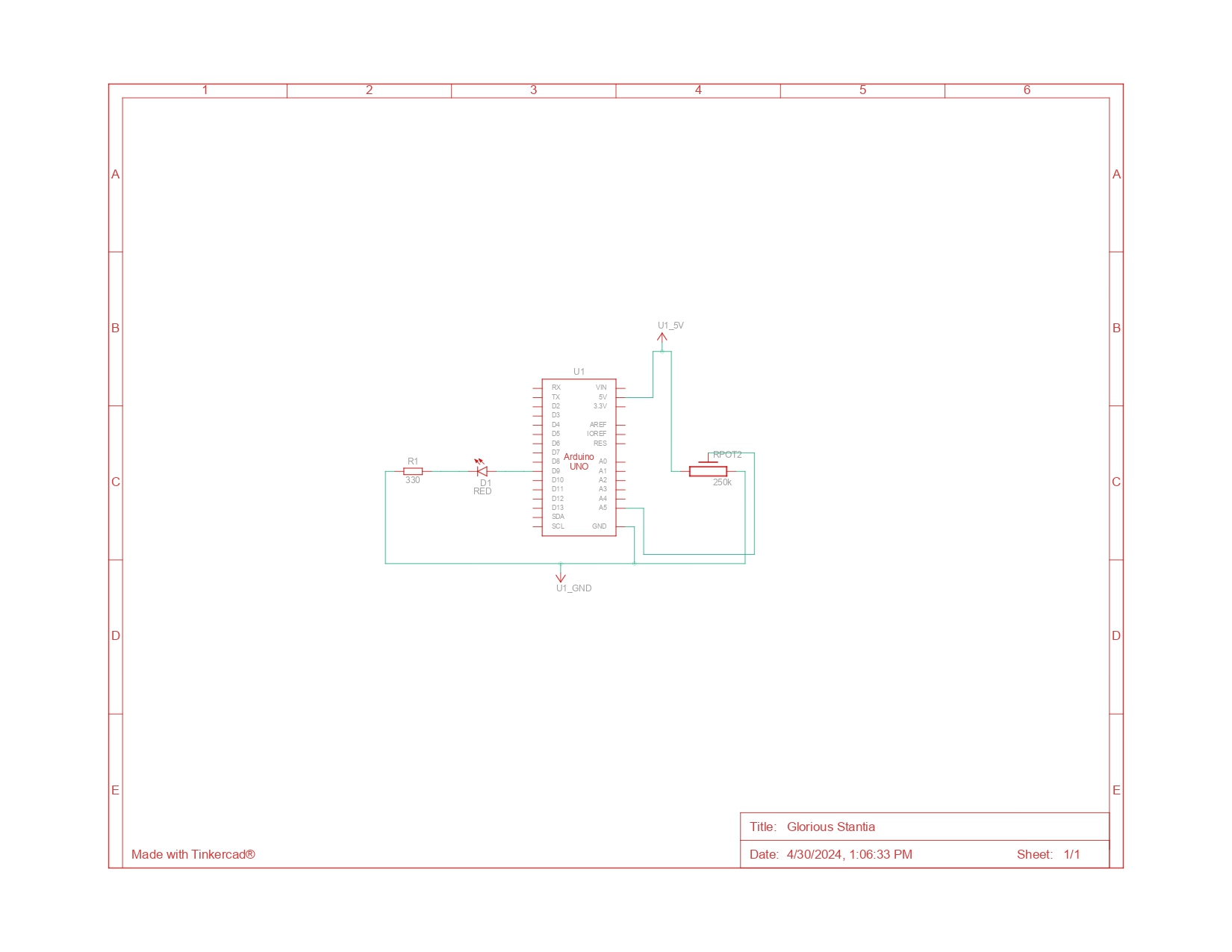
Take the gravity wind example and make it so: every time the ball bounces one led lights up and then turns off, and you can control the wind from one analog sensor.

Arduino Code:
arduino code : //Arduino Code

// Week 11.2 Example of bidirectional serial communication

// Inputs:
// - A0 - sensor connected as voltage divider (e.g. potentiometer or light sensor)
// - A1 - sensor connected as voltage divider 
//
// Outputs:
// - 2 - LED
// - 5 - LED

int leftLedPin = 10;
int rightLedPin = 5;

void setup() {
  // Start serial communication so we can send data
  // over the USB connection to our p5js sketch
  Serial.begin(9600);

  // We'll use the builtin LED as a status output.
  // We can't use the serial monitor since the serial connection is
  // used to communicate to p5js and only one application on the computer
  // can use a serial port at once.
  pinMode(LED_BUILTIN, OUTPUT);

  // Outputs on these pins
  pinMode(leftLedPin, OUTPUT);
  pinMode(rightLedPin, OUTPUT);

  // Blink them so we can check the wiring
  digitalWrite(leftLedPin, HIGH);
  digitalWrite(rightLedPin, HIGH);
  delay(200);
  digitalWrite(leftLedPin, LOW);
  digitalWrite(rightLedPin, LOW);


  // start the handshake
  while (Serial.available() <= 0) {
    digitalWrite(LED_BUILTIN, HIGH); // on/blink while waiting for serial data
    Serial.println("0,0"); // send a starting message
    delay(300);            // wait 1/3 second
    digitalWrite(LED_BUILTIN, LOW);
    delay(50);
  }
}

void loop() {
  // wait for data from p5 before doing something
  while (Serial.available()) {
    digitalWrite(LED_BUILTIN, HIGH); // led on while receiving data

    //int left = Serial.parseInt();
    int right = Serial.parseInt();
    int left = abs(right-1);
    if (Serial.read() == '\n') {
      digitalWrite(leftLedPin,left);
      digitalWrite(rightLedPin, right);
      int sensor = analogRead(A0);
      delay(5);
      int sensor2 = analogRead(A1);
      delay(5);
      Serial.println(sensor);
      //Serial.print(',');
      //Serial.println(sensor2);
    }
  }
  digitalWrite(LED_BUILTIN, LOW);
}
p5 sketch:

Please Click on the sketch and open it in Chrome to view :

Video Demonstration:


Reflections

This assignment taught us bidirectional communication. It was a useful stepping stone for arriving at the code for the final project . We had some issues in assignment 3 for communication between p5 and arduino but eventually we were able to solve it.

Overall, there was a lot to learn and it was good practice for coding for the final project