Week 12: Final Idea of Final project

Concept Overview

My final project idea is to develop an immersive and interactive surfing simulator game. The idea came to me when I went to the arcade and saw a snowboarding game and it sparked my interest to know how it was made and if I could replicate it with something I enjoyed and miss which is surfing. This game will use a physical skateboard found in the IM lab equipped with an accelerometer to capture the player’s movements, and a P5.js-based game that simulates a surfing and will have the concept of collecting and avoiding.

Inspo:

Extreme Snowboard – Toggi Fun World

Components

1. Arduino Setup:
Hardware: A skateboard with an accelerometer attached to its bottom. The accelerometer will detect tilt and motion, translating the player’s physical movements into digital inputs.

Functionality: The Arduino will continuously read the accelerometer data to determine the orientation and motion of the skateboard. This data will be sent to the P5.js game to control the virtual surfer’s movements.

2. P5.js Game Development:
Visual Interface: A surfing game created in P5.js, displaying a cat surfer surfing through the ocean. The game will have an avoiding and collecting concept.

Game Mechanics: The game will respond to the skateboard’s movements, controlling the surfer’s actions like speeding up, slowing down, turning, and performing tricks.

Feedback and Scoring: Visual and auditory feedback will be provided based on the player’s performance, along with a scoring system and life left.

3.Interaction Flow:
– The player stands on the skateboard and starts the game through a simple interface.
– As the player tilts and moves the skateboard, the accelerometer sends this data to the Arduino.
– The Arduino processes these movements and sends corresponding commands to the P5.js game.
– The game responds in real-time, translating these movements into the surfer’s actions on the screen.
– The player receives visual and audio feedback from the game, creating an engaging loop of action and response.

4.Design Considerations:
Responsiveness: Ensuring that it doesn’t feel or look shaky between physical movements and digital responses for a seamless experience.
User Safety: Designing the physical setup to be safe and stable for users of different skill levels.
Game Challenge: Balancing the game difficulty to be both fun and challenging, encouraging players to improve their skills.
Aesthetic Appeal: Creating an attractive and immersive game environment that enhances the overall experience.

5.Potential Challenges:
– Ensuring accurate and consistent data transmission from the accelerometer to the game.
– Balancing the physical skateboard movements with the digital game mechanics for a realistic surfing experience.
– Optimizing the game’s performance to prevent lag or glitches that could disrupt the immersive experience.

Conclusion
This project aims to create a novel gaming experience that blends physical activity with digital interaction, using Arduino and P5.js. It not only introduces a new way to play and enjoy a surfing game but also encourages physical movement, making gaming a more active experience.

Final Project – The Robot From 2023 – In 2300

Concept:

Imagine it’s the year 2100. They apparently discovered a robot from back in 2023 at the museum. They say it used to be the best at one point of time. Robots could just ‘talk’ back then, you know? And even that would be some inferior form of consciousness – simply mimicry. But oh wow, how it enchanted the people back then.

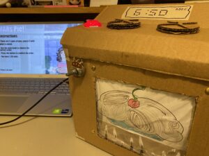
This is a project where the user can interact and communicate with a talking robot. In building this project I made extensive use of the ChatGPT API, for text generation and the p5.speech library for speech to text and text to speech. Additionally, I use the ml5.js library for person tracking that is done physically using a servo motor. Aesthetically, I was inspired by “Wall-E” to use the broken-down and creaky cardboard box aesthetic for my main moving robot head.

User Testing:

Implementation:

Interaction Design:

The user interacts with the robot by talking to it/moving around, patting the robot on its head, and turning a potentiometer/pressing a button. The robot tracks the user around making it seem conscious.

The talking aspect is simple, as in the robot listens to the user when the light is green, processes information when the indicator light is blue, and speaks when the indicator light is green – making it clear when the user can talk. The user can also press the “Click a photo” button and then ask a question to give the robot an image input too. Finally, the user can choose one of three possible moods for the robot – a default mode, a mode that gives the user more thoughtful answers, and a mode where the robot has an excited personality.

Arduino:

The Arduino controls the servo motor moving the robot head, the neopixels lights, the light sensor, the potentiometer and the two buttons. In terms of computations it computes what color the neopixels should be.

#include <Servo.h>
#include <Adafruit_NeoPixel.h>

// Pin where the NeoPixel is connected
#define PIN            11

// Number of NeoPixels in the strip
#define NUMPIXELS      12

// Create a NeoPixel object
Adafruit_NeoPixel strip = Adafruit_NeoPixel(NUMPIXELS, PIN, NEO_GRB + NEO_KHZ800);
Servo myservo;  // Create servo object
int pos = 90;   // Initial position
int neostate=0;
int onButton = 4;
int picButton = 7;
int potpin=A1;

void neo_decide(int neo){
  //starting
  if(neo==0)
  {
    setColorAndBrightness(strip.Color(100, 200, 50), 128); // 128 is approximately 50% of 255
    strip.show();
  }
  //listening
  else if(neo==1)
  {
    setColorAndBrightness(strip.Color(0, 255, 0), 128); // 128 is approximately 50% of 255
    strip.show();
  }
  //thinking
  else if(neo==2)
  {
    setColorAndBrightness(strip.Color(0, 128, 128), 128); // 128 is approximately 50% of 255
    strip.show();
  }
  //speaking
  else if(neo==3)
  {
    setColorAndBrightness(strip.Color(255, 0, 0), 128); // 128 is approximately 50% of 255
    strip.show();
  }
  //standby
  else
  {
    setColorAndBrightness(strip.Color(128, 0, 128), 128); // 128 is approximately 50% of 255
    strip.show();
  }
}

void setColorAndBrightness(uint32_t color, int brightness) {
  strip.setBrightness(brightness);
  for(int i = 0; i < strip.numPixels(); i++) {
    strip.setPixelColor(i, color);
    strip.show();
  }
}

void setup() {
  // Start serial communication so we can send data
  // over the USB connection to our p5js sketch
  myservo.attach(9);  // Attaches the servo on pin 9
  Serial.begin(9600);
  strip.begin();
  strip.show();
  pinMode(onButton, INPUT_PULLUP);
  pinMode(picButton, INPUT_PULLUP);
  // start the handshake
  while (Serial.available() <= 0) {
    digitalWrite(LED_BUILTIN, HIGH); // on/blink while waiting for serial data
    Serial.println("0"); // send a starting message
    delay(300);            // wait 1/3 second
    digitalWrite(LED_BUILTIN, LOW);
    delay(50);
  }
}

void loop() {
  // wait for data from p5 before doing something
  while (Serial.available()) {
    digitalWrite(LED_BUILTIN, HIGH); // led on while receiving data

    pos = Serial.parseInt();
    neostate = Serial.parseInt();
    neo_decide(neostate);
    if (Serial.read() == '\n') {
      myservo.write(pos);   // Move servo to position
      int lightstate=analogRead(A0);
      int onbuttonstate=digitalRead(onButton);
      int picbuttonstate=digitalRead(picButton);
      int potstate=analogRead(potpin);
      Serial.print(lightstate);
      Serial.print(',');
      Serial.print(potstate);
      Serial.print(',');
      Serial.print(onbuttonstate);
      Serial.print(',');
      Serial.println(picbuttonstate);
    }
  }
  digitalWrite(LED_BUILTIN, LOW);
}


P5.js

The p5.js code does most of the work for this project. Firstly, it handles the API calls to GPT3.5 Turbo and GPT-4-vision-preview models. When the user is talking to the robot normally, I send the API calls to the cheaper GPT3.5 turbo model, when the user wants to send an image input, I convert all the previously sent inputs into the format necessary for the GPT4-vision-preview model along with the image.

Second, I use the ml5.js library and the ‘cocossd’ object detection model to detect a human on the camera field of vision and draw a bounding box around it. Then we take the center of the bounding box and attempt to map the servo motor’s movement to this.

The text to speech and speech to text functionalities are done using the p5.Speech library. While doing this, we keep a track of what state we are in currently.

Lastly, we also keep track of whether the system is on right now, the light sensor’s values, and whether the click a photo button was pressed. The ‘on’ button, as the name suggests acts as a toggle for the system’s state, the light sensor starts a specific interaction when it’s value is below a threshold, and the photo button informs us about which API call to make.

Finally, we can also switch between the model’s different personalities by using the potentiometer and this is handled in the updateMood() function.


Communication between Arduino – P5

The Arduino communicates the button states, the potentiometer state, and the light sensor state to the p5.js program and receives inputs for the neopixel state, and the servo motor state.

Highlights:

For me the highlights of this project have to be designing the physical elements and handling the complex API call mechanics. Due to the fact that I use two different models that have different API input structures, the transformation between them was time-consuming to implement. Additionally, the p5.speech library that I use extensively is relatively unreliable and took a lot of attempts for me to use correctly.

Additionally, it was exciting to watch the different ways people interacted with the robot at the IM showcase. A large percent of people were interested in using the robot as a fashion guide assistant! I think overall, this was a really interesting demonstration of the potential of generative AI technology and I would love to build further using it!

Future Work:

There are several features I would love to add to this project in future iterations. Some of these include:

  • Do a basic talking animation by moving the robot’s head up and down during the talking phase. Additionally, perhaps make the robot mobile so it can move about.
  • Make the camera track the person in the front. This can be done by making the person wear a specific object – or some sophisticated ML trick.
  • Have additional interactions and add parts to the robot such as more expressive ears etc.
  • Use a more robust box and fit the arduino breadboard, camera, speaker etc. inside the robot head.
  • Make the neopixels implementation more aesthetic by employing colored patterns and animations.


Final Project – Mastermind

Concept

As I mentioned in a previous post, I wanted to make a Mastermind game, which is a two-player board game where one person is the code maker, and they make a code using colored pegs. The other person is the code breaker, and they have to figure out the code in a limited number of moves. The less moves you take to figure out the code, the higher you score.
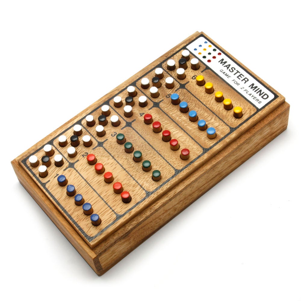
Mastermind - Code Breaking Game – Kubiya GamesIn the version that I made, this game is actually a 1-player game, where the code is randomly generated, and the players have to guess the code. Players use a physical system of colored pegs and holes to parse input to the board.

Final Game
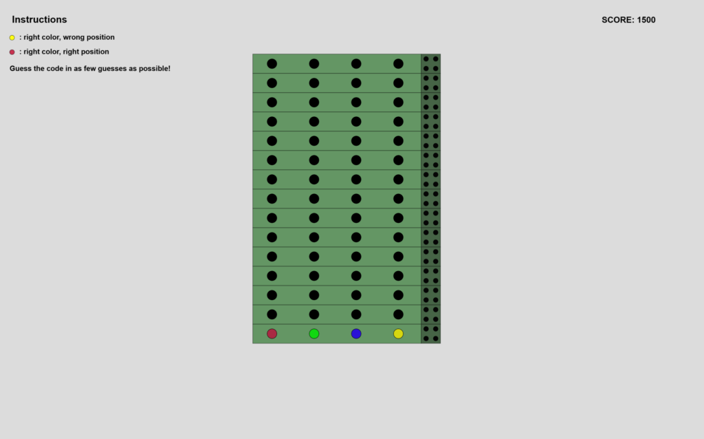
I’m very happy with the final P5Js interface for the game. It’s very minimalistic, which matches the style that I’ve chosen to go with for all of my projects. The instructions are in the upper left corner, as I didn’t want to clutter the interface by adding buttons to other pages. Also, I wanted to keep interaction with the laptop minimal if not zero, so I opted to have a static screen and focus on the physical input interface.

P5Js Sketch

The sketch does require a serial connection with Arduino. However, I enabled skipping the serial connection check for the purposes of viewing the sketch without an Arduino connection. You can press the “space” key to skip to the game screen. I have also edited the aspect ratio, for viewing it successfully within the Intro to IM blog post. It’s best viewed in fullscreen mode.

The Physical System

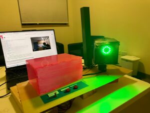
The control interface consists of a box with 5 colored pegs. In the picture below, you can see how the pegs fit into the console, and how the order can be changed to alter the input.
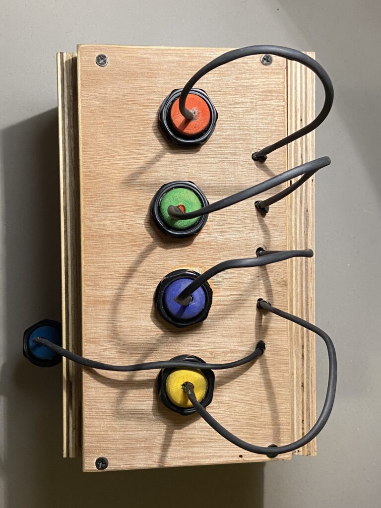
 

There is also a button on the left side of the interface, which can be pressed to confirm your choice. I used an LED momentary button because it reminded me of retro gaming consoles.
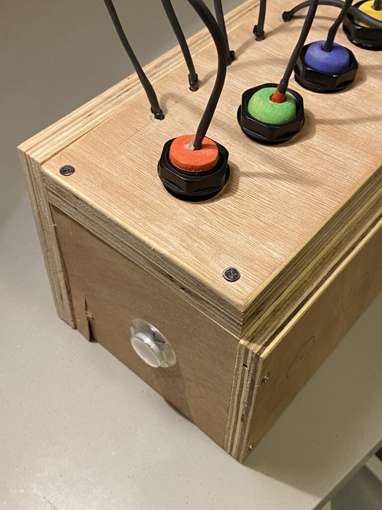
The color detection mechanism is rather naive, and it became a pain later on during the showcase as well. I have embedded LEDs in each peg, and each LED has a specific level of brightness. There is a single light sensor (LDR) in each of the 4 holes, which measures the brightness once a peg is placed into the hole. Depending on the brightness of the LED, a value corresponding to the respective color is generated. In the case of yellow, this would be the value “3”, which is the index in the array that contains the color values, as well as the index in which the pegs are fixed into the console, if you start counting from 0.
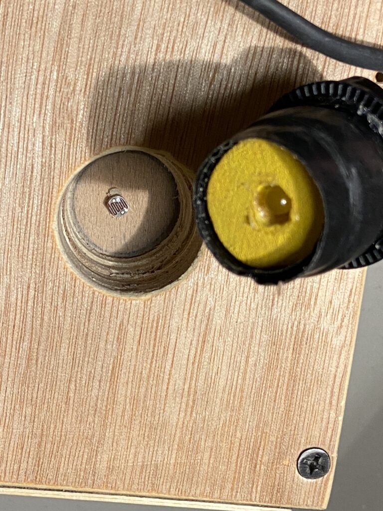
To ensure the fit was tight for consistent readings, I wrapped electrical tape around the pegs until there was a snug fit.

User Testing

I asked my friend to test the game for me. I told her nothing about how to use the interface, but she already knew about Mastermind.

She found the interface intuitive to use, but I think that it wasn’t as clear for people who didn’t know the game beforehand.

In the end, my friend won the game:

Circuit

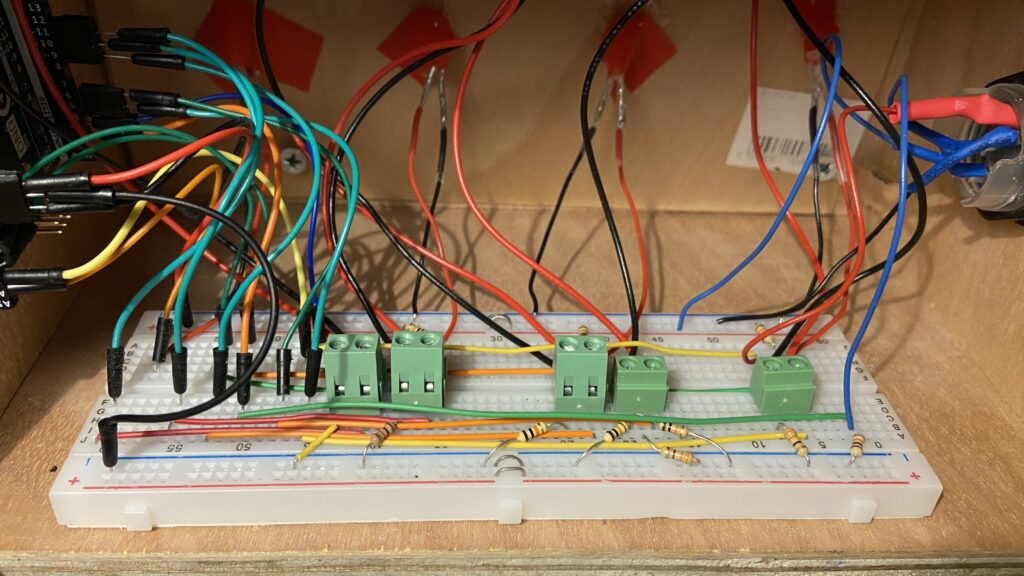
I wanted to keep the circuit as neat as possible, so I kept the Arduino on one side of the box, had a long breadboard in the middle, and the wires connecting to the closest part of the breadboard to the corresponding hardware. I then used jumper wires to complete the circuit on the breadboard.
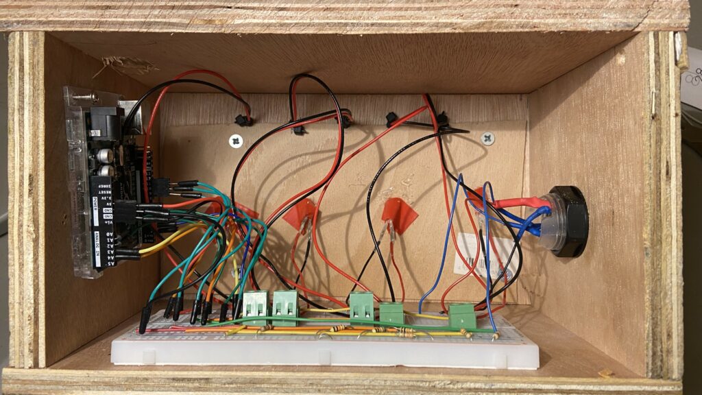
I soldered the wires onto the LDRs and LEDs, and then use screw mounts to connect the other ends to the breadboard. I did the same for the LED button as well.
Communication Between P5Js and Arduino

I only implemented one way communication, as the goal was to have Arduino serve only as an input device. Therefore, I just sent the state of the current row of the game as an integer code, as well as a binary value showing whether or not the button to lock in the choice was pressed.

Challenges

The most challenging aspect was calibrating the LDRs and tuning them so that each color had a particular range. However, due to the sensitivity of the LDRs, it was hard to have the LDR value ranges for each color not intersect. There was a tradeoff, as if I chose to spread out the ranges for each color, it would mean that some colors would have the same brightness as the ambient brightness, which would end up showing that color throughout the board. I chose to keep this in for the sake of having more consistency in the input, but I realize that that decision made the game confusing for some people.

Aspects that I’m proud of

I really like the aesthetics of the game overall, and I think that the P5Js aspect of the project was done very well. There are definitely some features that I would have liked to implement, but the things that I chose to keep in were well done.

I’m also proud of the way I handled an issue that occurred. Since I’m using light sensors, the mechanism needed recalibration whenever the ambient brightness changed. To tackle this, I took two approaches.
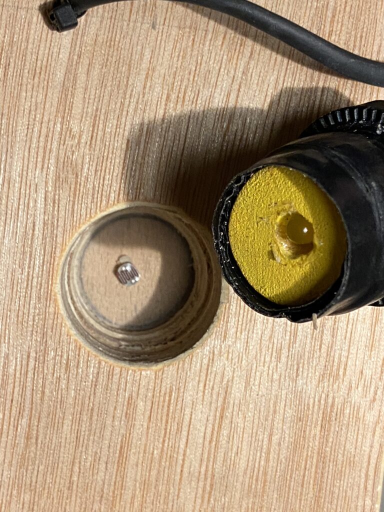
Firstly, I took some plastic nuts from the large LED buttons and fixed them on top of the knobs to block out any light from the cracks around the knob. To make sure that there was absolutely no light coming through from around the peg, I wrapped it in tape until it fit snugly. This was the physical steps that I took.

Secondly, I created a calibration script within Arduino. When I needed to calibrate the settings, I would run this, and it would tell me what settings I need for the current environment based on the minimum and maximum readings for each color across all the light sensors. The code for that is below:

void calibrateColorRanges()
{
  Serial.println("Calibration started. Please follow the instructions to calibrate each color.");

  const int numColors = 5; // Assuming 5 colors: Red, Green, Blue, Yellow, Turquoise
  const int numLDRs = 4;   // Assuming 4 LDRs

  int calibrationValues[numColors][2]; // Array to store min and max values for each color across all LDRs

  for (int color = 0; color < numColors; color++)
  {
    Serial.print("Calibrating ");
    switch (color)
    {
    case 0:
      Serial.print("RED");
      break;
    case 1:
      Serial.print("GREEN");
      break;
    case 2:
      Serial.print("BLUE");
      break;
    case 3:
      Serial.print("YELLOW");
      break;
    case 4:
      Serial.print("TURQUOISE");
      break;
    }
    Serial.println("...");

    // Initialize min and max values
    calibrationValues[color][0] = 1023; // Initial min value
    calibrationValues[color][1] = 0;    // Initial max value

    for (int ldr = 0; ldr < numLDRs; ldr++)
    {
      Serial.print("Move ");
      switch (color)
      {
      case 0:
        Serial.print("RED");
        break;
      case 1:
        Serial.print("GREEN");
        break;
      case 2:
        Serial.print("BLUE");
        break;
      case 3:
        Serial.print("YELLOW");
        break;
      case 4:
        Serial.print("TURQUOISE");
        break;
      }
      Serial.print(" to LDR ");
      Serial.print(ldr + 1);
      Serial.println(" and press Enter.");

      // Wait for user input (press Enter in the Serial Monitor)
      while (!Serial.available())
      {
        delay(100);
      }

      // Discard any existing input
      while (Serial.available())
      {
        Serial.read();
      }

      // Perform readings and find min and max values
      for (int i = 0; i < 100; i++)
      {
        int ldrValue = analogRead(LDR_1 + ldr);

        // Update min and max values
        calibrationValues[color][0] = min(calibrationValues[color][0], ldrValue);
        calibrationValues[color][1] = max(calibrationValues[color][1], ldrValue);

        delay(10); // Delay between readings
      }
    }

    // Display the min and max values for the current color across all LDRs
    Serial.print("Min value: ");
    Serial.print(calibrationValues[color][0]);
    Serial.print(", Max value: ");
    Serial.println(calibrationValues[color][1]);
  }

  Serial.println("Calibration complete. Use the following values in getColorFromLdrVal function:");
  for (int color = 0; color < numColors; color++)
  {
    Serial.print("Color ");
    switch (color)
    {
    case 0:
      Serial.print("RED");
      break;
    case 1:
      Serial.print("GREEN");
      break;
    case 2:
      Serial.print("BLUE");
      break;
    case 3:
      Serial.print("YELLOW");
      break;
    case 4:
      Serial.print("TURQUOISE");
      break;
    }
    Serial.print(": Min - ");
    Serial.print(calibrationValues[color][0]);
    Serial.print(", Max - ");
    Serial.println(calibrationValues[color][1]);
  }
}

Although some other approach might have been more elegant, I think that I was able to manage even with the drawbacks of the design that I selected.

Future Ideas

  • I think it would be fun to add a leaderboard. Since I have score metrics already, it would be more fun if people competed against people who played the game previously.
  • It would be nice to have the option for players to play as codemakers as well, since the original game is a two-player game. That would make my project true to the original.
  • It would be better if I had the calibration embedded into the P5Js sketch, so that there is no need to reflash the Arduino. Currently, the way that I do it is to reflash the Arduino with the calibration command, and then flash it again after calibrating it, which is a nuisance.

Arduino Code

#include <Arduino.h>

// colors as ints
const int RED = 0;
const int GREEN = 1;
const int BLUE = 2;
const int YELLOW = 3;
const int TURQUOISE = 4;

// 5 LEDS with variable brightness on Arduino UNO
// LEDs are connected to pins 3, 5, 6, 9, 10
const int LED_PINS[] = {5, 6, 9, 10, 11};

const String colors[] = {"R", "G", "B", "Y", "T", "N"}; // red, green, blue, yellow, turquoise, none
// different brightness levels for LEDS
const int brightnessLevels[] = {LOW, HIGH, HIGH, HIGH, HIGH};
// const int brightnessLevels[] = {10, 0, 4, 153, 255};

// 4 LDRS connected to pins A1, A2, A3, A4
const int LDR_1 = A1; // 15
const int LDR_2 = A2; // 16
const int LDR_3 = A3; // 17
const int LDR_4 = A4; // 18

// 4 variables to store the values from the LDRs
int ldrValue1 = 0;
int ldrValue2 = 0;
int ldrValue3 = 0;
int ldrValue4 = 0;

// button LED
const int buttonLED = 3;
const int buttonPin = 2;

void setup()
{
  // initialize serial communication at 9600 bits per second:
  Serial.begin(9600);
  // initialize the LED pins as an output:
  for (int i = 0; i < 5; i++)
  {
    pinMode(LED_PINS[i], OUTPUT);
  }

  // initialize the LDR pins as an input:
  pinMode(LDR_1, INPUT);
  pinMode(LDR_2, INPUT);
  pinMode(LDR_3, INPUT);
  pinMode(LDR_4, INPUT);

  pinMode(buttonLED, OUTPUT);
  pinMode(buttonPin, INPUT_PULLUP);
}

const int minRed = 980;
const int maxRed = 1023;
const int minGreen = 610;
const int maxGreen = 940;
const int minBlue = 220;
const int maxBlue = 460;
const int minYellow = 120;
const int maxYellow = 220;
const int minTurquoise = 0;
const int maxTurquoise = 70;
int ambientLight[] = {0, 0, 0, 0};

int getColorFromLdrVal(int ldrVal, int ambientLight)
{
  if (ldrVal >= minRed && ldrVal <= maxRed) // range of
  {
    return RED;
  }
  if (ldrVal >= minGreen && ldrVal <= maxGreen) // range of 175
  {
    return GREEN;
  }
  if (ldrVal >= minBlue && ldrVal < maxBlue) // range of 310
  {
    return BLUE;
  }
  if (ldrVal >= minYellow && ldrVal <= maxYellow) // range of 70
  {
    return YELLOW;
  }

  if (ldrVal >= minTurquoise && ldrVal <= maxTurquoise) // range of 80
  {
    return TURQUOISE;
  }

  else
  {
    return 5;
  }
}

void calibrateColorRanges()
{
  Serial.println("Calibration started. Please follow the instructions to calibrate each color.");

  const int numColors = 5; // Assuming 5 colors: Red, Green, Blue, Yellow, Turquoise
  const int numLDRs = 4;   // Assuming 4 LDRs

  int calibrationValues[numColors][2]; // Array to store min and max values for each color across all LDRs

  for (int color = 0; color < numColors; color++)
  {
    Serial.print("Calibrating ");
    switch (color)
    {
    case 0:
      Serial.print("RED");
      break;
    case 1:
      Serial.print("GREEN");
      break;
    case 2:
      Serial.print("BLUE");
      break;
    case 3:
      Serial.print("YELLOW");
      break;
    case 4:
      Serial.print("TURQUOISE");
      break;
    }
    Serial.println("...");

    // Initialize min and max values
    calibrationValues[color][0] = 1023; // Initial min value
    calibrationValues[color][1] = 0;    // Initial max value

    for (int ldr = 0; ldr < numLDRs; ldr++)
    {
      Serial.print("Move ");
      switch (color)
      {
      case 0:
        Serial.print("RED");
        break;
      case 1:
        Serial.print("GREEN");
        break;
      case 2:
        Serial.print("BLUE");
        break;
      case 3:
        Serial.print("YELLOW");
        break;
      case 4:
        Serial.print("TURQUOISE");
        break;
      }
      Serial.print(" to LDR ");
      Serial.print(ldr + 1);
      Serial.println(" and press Enter.");

      // Wait for user input (press Enter in the Serial Monitor)
      while (!Serial.available())
      {
        delay(100);
      }

      // Discard any existing input
      while (Serial.available())
      {
        Serial.read();
      }

      // Perform readings and find min and max values
      for (int i = 0; i < 100; i++)
      {
        int ldrValue = analogRead(LDR_1 + ldr);

        // Update min and max values
        calibrationValues[color][0] = min(calibrationValues[color][0], ldrValue);
        calibrationValues[color][1] = max(calibrationValues[color][1], ldrValue);

        delay(10); // Delay between readings
      }
    }

    // Display the min and max values for the current color across all LDRs
    Serial.print("Min value: ");
    Serial.print(calibrationValues[color][0]);
    Serial.print(", Max value: ");
    Serial.println(calibrationValues[color][1]);
  }

  Serial.println("Calibration complete. Use the following values in getColorFromLdrVal function:");
  for (int color = 0; color < numColors; color++)
  {
    Serial.print("Color ");
    switch (color)
    {
    case 0:
      Serial.print("RED");
      break;
    case 1:
      Serial.print("GREEN");
      break;
    case 2:
      Serial.print("BLUE");
      break;
    case 3:
      Serial.print("YELLOW");
      break;
    case 4:
      Serial.print("TURQUOISE");
      break;
    }
    Serial.print(": Min - ");
    Serial.print(calibrationValues[color][0]);
    Serial.print(", Max - ");
    Serial.println(calibrationValues[color][1]);
  }
}

unsigned long timeSinceLastSerial = 0;
int valFromP5 = 0;

float sum1, sum2, sum3, sum4 = 0;
unsigned int ldrVal1, ldrVal2, ldrVal3, ldrVal4 = 0;
unsigned int iterator = 0;

unsigned long buttonLEDTimer = 0;
unsigned long buttonSendTimer = 0;

int buttonBrightness = 0;
int buttonDirection = 1;

int buttonState = LOW; // if button is not pressed

void loop()
{

  // fade in and out button LED
  if (millis() - buttonLEDTimer > 5)
  {
    buttonLEDTimer = millis();
    if (buttonBrightness >= 255 || buttonBrightness <= 0)
    {
      buttonDirection = buttonDirection * -1;
    }

    buttonBrightness = (buttonBrightness + 1 * buttonDirection);
    if (buttonBrightness >= 255)
    {
      buttonBrightness = 255;
    }
    if (buttonBrightness <= 0)
    {
      buttonBrightness = 0;
    }
    analogWrite(buttonLED, buttonBrightness);
  }

  // turn on the LEDs to the corresponding brightness
  digitalWrite(LED_PINS[RED], brightnessLevels[RED]);
  digitalWrite(LED_PINS[GREEN], brightnessLevels[GREEN]);
  digitalWrite(LED_PINS[BLUE], brightnessLevels[BLUE]);
  digitalWrite(LED_PINS[YELLOW], brightnessLevels[YELLOW]);
  digitalWrite(LED_PINS[TURQUOISE], brightnessLevels[TURQUOISE]);

  // uncomment to calibrate color ranges
  // calibrateColorRanges();

  // send to processing
  if (millis() - timeSinceLastSerial < 10) // if it has not been more than 20ms since last serial message
  {
    return; // do nothing
  }

  timeSinceLastSerial = millis(); // update the time since last serial message

  if (iterator == 10)
  {
    ldrVal1 = int(sum1 / 10);
    ldrVal2 = int(sum2 / 10);
    ldrVal3 = int(sum3 / 10);
    ldrVal4 = int(sum4 / 10);

    // print the values if they are not nan
    if (!isnan(ldrVal1) && !isnan(ldrVal2) && !isnan(ldrVal3) && !isnan(ldrVal4))
    {

      // get the color from the LDR value
      int color1 = getColorFromLdrVal(ldrVal1, ambientLight[0]);
      int color2 = getColorFromLdrVal(ldrVal2, ambientLight[1]);
      int color3 = getColorFromLdrVal(ldrVal3, ambientLight[2]);
      int color4 = getColorFromLdrVal(ldrVal4, ambientLight[3]);
      int buttonState = digitalRead(buttonPin);

      Serial.print(color1);
      Serial.print(",");
      Serial.print(color2);
      Serial.print(",");
      Serial.print(color3);
      Serial.print(",");
      Serial.print(color4);
      Serial.print(",");
      Serial.println(buttonState);
    }

    iterator = 0;
    sum1 = 0;
    sum2 = 0;
    sum3 = 0;
    sum4 = 0;
  }

  // read and add values from the LDRs
  sum1 = sum1 + analogRead(LDR_1);
  sum2 = sum2 + analogRead(LDR_2);
  sum3 = sum3 + analogRead(LDR_3);
  sum4 = sum4 + analogRead(LDR_4);

  iterator++;
}

P5Js Code

let board;

let WIDTH = 2800;
let HEIGHT = 1500;
let colorsArray;

const RED = 0;
const GREEN = 1;
const BLUE = 2;
const YELLOW = 3;
const TURQUOISE = 4;
const BLACK = 5;

let canvas;
let port;

let highScores = [];


function generateCode() {
 let code = [];
  let array = [0, 1, 2, 3 , 4, 5];
  //select random subset of 4 colorsArray
  let colorsArray = shuffleArray(array);

  for (let i = 0; i < 4; i++) { // select only 4 colorsArray
    code.push(colorsArray[i]);
  }

  return code;
}

// Helper function to shuffle an array
function shuffleArray(array) {
  //copy the array
  array_copy = array.slice();

  for (let i = array_copy.length - 2; i > 0; i--) {
    const j = Math.floor(Math.random() * (i + 1));
    [array_copy[i], array_copy[j]] = [array_copy[j], array_copy[i]];
  }
  return array_copy;
}


function calculateScore(numGuesses) {
  return 1500 - 100 * numGuesses;
}

let r, g, b, y, t, bl;


let currentGuess;
let numberOfGuesses;
let lastButtonPressed;
let isButtonPressed;
let buttonClock;
let board_score;
let state;


function setup() {
  canvas = createCanvas(WIDTH, HEIGHT);
  board = new Board();

  r = color(200, 50, 80);
  g = color(20, 255, 20);
  b = color(50, 20, 255);
  y = color(255, 255, 20);
  t = color(20, 255, 255);
  bl = color(0, 0, 0);


  // colorsArray are red, green, blue, yellow, turquoise, black
  colorsArray = [r, g, b, y, t, bl];

  //generate the code
  code = generateCode();

  port = createSerial();

  //initialize important variables
  numberOfGuesses = 0;
  lastButtonPressed = 0;
  isButtonPressed = 0;
  buttonClock = 0;

  board_score = [0, 0];

  state = "AUTH_STATE";

}

function resetGame()
{
  board.reset();
  numberOfGuesses = 0;
  score = 0;
  state = "AUTH_STATE";
  code = generateCode();

}


function getNameInput()
{
  let name = prompt("Please enter your name ");
  if (name == null || name == "") {
    name = "Anonymous";
  }
  return name;
}


let delayClock = 0;
function draw() {

  if (state == "GAME_STATE") {
    background(220);

    board_score = board.score;
      print("score: " + board_score);

      if (board_score[0] == 4) {
        print("GAME WON")
        state = "GAME_WON_STATE";

        delayClock = millis();
      }

      if (board.currentRow == 15) {
        print("GAME LOST")
        state = "GAME_LOST_STATE";
        delayClock = millis();

      }

    // if the port is open, read the data
    if (port.available() > 0) {
      let data = port.readUntil("\n");

      split_data = int(data.split(","));

      // first 4 are the current guess
      // last is the button press
      currentGuess = split_data.slice(0, 4);
      isButtonPressed = split_data[4];
      board.update(currentGuess);
    }


    //if the button is pressed, finalize the guess
    if (isButtonPressed == 1 && lastButtonPressed == 0) {
      if (board.finalizeChoices(code))
      {
        numberOfGuesses++;
      };
      lastButtonPressed = 1;
    }

  
    else if (isButtonPressed == 0 && lastButtonPressed == 1) {
      lastButtonPressed = 0;
    }


    board.show();

    //show the score at the top right
    fill(0);
    textSize(35);
    push();
    textStyle(BOLD);
    text("SCORE: " + calculateScore(numberOfGuesses), width - 300, 100);
    pop();

    // print instructions to the side 
    fill(0);
    textSize(40);

    push();
    textStyle(BOLD);
    text("Instructions", 50, 100);
    pop();

    textSize(30);
    
    push(); 
    fill(y);
    circle(50, 162, 20);
    pop();
    text(": right color, wrong position", 80, 170);

    // red circle 
    push();
    fill(r);
    circle(50, 222, 20);    
    pop();

    text(": right color, right position", 80, 230);

    text("Guess the code in as few guesses as possible!", 40, 300);


  }

  else if (state == "GAME_WON_STATE") {
    background(220, 200);
    fill(0);
    textSize(60);
    textStyle(BOLD);
    text("YOU WON!", width / 2 - 200, height / 2);

    //SHOW SCORE
    fill(0);
    textSize(35);
    push();
    textStyle(BOLD);
    text("SCORE: " + calculateScore(numberOfGuesses), width / 2 - 200, height / 2 + 100);
    pop();


    if (millis() - delayClock < 2000) {
      return;
    }


    //read input from the serial port
    if (port.available() > 0) {
      let data = port.readUntil("\n");
      
      data = int(data.split(","));

      let buttonval = data[4];
      if (buttonval == 1) {
        print("resetting");
        board.reset();
        numberOfGuesses = 0;
        state = "GAME_STATE";
        board_score = [0, 0];
      }
    }
  }

  else if (state == "GAME_LOST_STATE") {
    background(220, 200);
    fill(0);
    textSize(60);
    textStyle(BOLD);
    text("YOU LOST!", width / 2 - 200, height / 2);

    text("The code was: ", width / 2 - 600, height / 2 + 200);
    //print the right code
    for (let i = 0; i < 4; i++) {
      push();
      fill(colorsArray[code[i]]);
      circle(width/2 - 100 + i * 100, height/2 + 185, 50);
      pop();
    }

    //push the button to reset
    push();
    textSize(30);
    text("Press the button to reset", width / 2 - 200, height / 2 + 400);
    pop();


    if (millis() - delayClock < 2000) {
      return;
    }

    //read input from the serial port
    if (port.available() > 0) {
      let data = port.readUntil("\n");
      
      data = int(data.split(","));

      let buttonval = data[4];
      if (buttonval == 1) {
        print("resetting");
        resetGame();
      }
    }
  }


  else if (state == "AUTH_STATE") {

    //ask to connect to the device
    background(220, 200);
    fill(0);
    textSize(60);
    textStyle(BOLD);
    text("PRESS SPACE TO START", width / 2 - 300, height / 2);

    if(port.opened()) {
      state = "GAME_STATE";
    }

  }


}


/**
 * Handles key press events and performs corresponding actions.
 */
function keyPressed() {
  /**
   * If the key pressed is "c" and the state is "GAME_STATE",
   * finalize the choices on the board using the provided code.
   *
   * @returns {void}
   */
  if (key == "c") {
    if (state != "GAME_STATE") {
      return;
    }
    board.finalizeChoices(code);
  }
}

  /**
   * If the key pressed is "n", update the current color of the current row on the board.
   * The color is updated by incrementing the current color index by 1 and wrapping around to 0 if it exceeds 5.
   *
   * @returns {void}
   */
  if (key == "n") {
    board.rows[board.currentRow].currentColor = (board.rows[board.currentRow].currentColor + 1) % 6;
  }

  /**
   * If the key pressed is " " (space) and the state is "AUTH_STATE",
   * open a port at 9600 baud using the port object.
   *
   * @returns {void}
   */
  if (key == " ") {
    if (state != "AUTH_STATE") {
      return;
    }
    port.open(9600);
  }

  /**
   * If the key pressed is "r", reset the game.
   *
   * @returns {void}
   */
  if (key == "r") {
    resetGame();
  }
}
Week 11 Final project idea

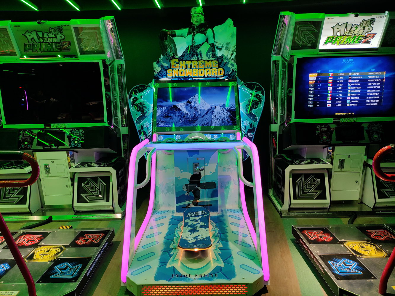
My final project idea is to develop an immersive and interactive surfing simulator game. The idea came to me when I went to the arcade and saw a snowboarding game and it sparked my interest to know how it was made and if I could replicate it with something I enjoyed and miss which is surfing. This game will use a physical skateboard found in the IM lab equipped with an accelerometer to capture the player’s movements, and a P5.js-based game that simulates a surfing and will have the concept of collecting and avoiding.


This is the inspiration below:

Extreme Snowboard – Toggi Fun World

Week 11- Nourhane’s Reading Response

Reading Graham Pullin’s “Design Meets Disability” was like opening a window to a new world of possibilities in design. Pullin’s approach is transformative, merging concepts like simplicity, universality, exploratory problem-solving, fashion, and discretion into a cohesive vision for disability aids. He challenges the traditional, function-first mindset and proposes a more inclusive, style-conscious approach, arguing that assistive devices should be as much a statement of personal style as they are functional.

Pullin’s ideas are inspiring, urging us to think beyond the conventional. He’s not just talking about making things easier to use but also about embracing the diversity of users. His call for a blend of aesthetics and functionality in design resonates with me. It’s a fresh take that adds dignity and choice to the equation, offering people with disabilities more than just practical solutions but also products they can feel good about using.

However, as a student thinking critically, I see challenges in Pullin’s vision. His idealistic approach makes me wonder about the real-world implications. How do we balance these ambitious design goals with practical constraints like cost, manufacturing complexities, and the varied needs of individuals with disabilities? It’s one thing to dream of stylish, universally accessible designs, but another to implement them in a way that’s affordable and accessible to all.

“Design Meets Disability” has definitely broadened my understanding of what design can and should do. It’s pushed me to think about how we can make the world more inclusive through thoughtful design. But it’s also left me with questions about the balance between idealism and feasibility. How do we make these innovative designs a reality for everyone who needs them, not just those who can afford them? It’s a challenging question, and Pullin’s book is a compelling starting point for this important conversation.

Final Project: Mar’s Pie Shop

CONCPET:

I love baking, and I enjoy baking games. For my final project I decided to make a pie shop… Throughout my journey in Intro to IM, I made sure to always add a piece of me in every assignment and project. This final one is especially dear to me because I was able to finalize it after hard work. As well as being able to add my art in it (background and pie images). I think it goes well together and I’m proud of it.

FUN FACT: I have never had pie in my life!!!

HIGHLIGHT OF MY CODE IN P5.JS:

Entire Code: https://editor.p5js.org/mariamalkhoori/sketches/VUY94T9vh

-Function to check the correct match

function submitAnswer() {
  // Define the expected ranges for each statement
  const rawRange = [0, 200];
  const undercookedRange = [201, 400];
  const perfectRange = [401, 600];
  const overcookedRange = [601, 800];
  const burntRange = [801, 1023];

  let expectedRange;

  // Determine the expected range based on the current sentence
  switch (currentSentence) {
    case "I would like a raw pie to bake at home.":
      expectedRange = rawRange;
      break;
    case "I like my pie extremely soft.":
      expectedRange = undercookedRange;
      break;
    case "I want a perfect pie!":
      expectedRange = perfectRange;
      break;
    case "Crispy around the edges!!":
      expectedRange = overcookedRange;
      break;
    case "BURNT IT >:D":
      expectedRange = burntRange;
      break;
  }

  // Check if the current image range matches the expected range
  if (x >= expectedRange[0] && x <= expectedRange[1]) {
    // Increment the score for a correct match
    score++;
    
  ding.play();

-Different screen pages:


if (gameState === "start") {
  drawStartScreen();
} else if (gameState === "playing") {
  displayFoodImage();
  displayTimer();
  textSize(24);
  fill(255);
  text("Score: " + score, width - 100, 30);
} else if (gameState === "end") {
  // Display results in the end screen
  textSize(210);
  fill(255);
  text("Your Score: " + score, width / 2, height / 2);
  playAgainButton.show(); // Show the button on the end screen
}
else {
  // Draw other game elements here
  playAgainButton.hide(); // Hide the button if not in the end state
}

main COMPONENTS:

-LED Button

-Potentiometer

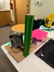
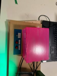
OVEN PROTOTYPE AND SCHEMATICS:


USER TESTING:


CHALLENGES:

  • Many challenges were faced with the coding part.
  • Button wasn’t working to confirm answers and also change the requests of the order.
  • Sometimes the images controlled by the potentiometer would not show, or not change.
  • I also had some issues with serial connection because of the wirings

FUTURE IMPORVEMENTS:

  • I hoped to be able to make the game restart without having to exit full screen.
  • Make the prototype a little prettier
  • Fine-tune the difficulty level based on user feedback. Adjust timer durations, scoring mechanisms, or image recognition ranges to make the game challenging yet enjoyable.
  • Introduce new challenges or power-ups to add variety to the gameplay.
  • Ensure that the game is responsive and looks good on various screen sizes.
  • I wanted to add a leaderboard to display at the end

IM SHOWCASE:

week13&14 – final project documentation

USER TESTING:
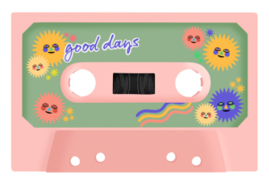
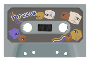
My deliverable was still at a premature stage so I was unable to film a user-testing video, however I was able to get verbal feedback on my p5 program design (and so have adjusted my code accordingly). Initially, I had no text to indicate any sort of instructions or context, as I had thought the arrow buttons were enough to prompt users into action. However, my sister advised against this and suggested I include a phrase or 2 to provide basic information as to what my project is about – even more so since I did not have a start/ introductory screen. Another feedback I got was regarding the separate display screen for when the recommended playlist sounds – which was mentioned in the previous documentation. I was initially just planning to display the user’s chosen personalised cassette however my sister thought it to be too static, commenting that it was lacking flair. I starting brainstorming other potential display screens I could have but the one that resonated most with me was actually animating a rolling cassette tape, of course this would mean I had to create animations for all possible cassette tape designs.

Final project video: https://youtu.be/t_wIKjY5s1o

My final project concept is based off of my midterm project. In the previous midterm, I made a digital radio that played 2 meaningful songs. Each song displayed (what was supposed to be) a dynamic background of a personal memory associated with the songs. My final project builds off on this idea but with an added twist. You are able to customise your own cassette tape and based on your choices, it assembles a recommended playlist. There are 3 choices in each stage of customizing for the personalisation of your cassette and when finished, it plays a recommended playlist of 4 songs, each similar in genre. You can adjust the volume, use a skip function and reset the entire experience through physical means (buttons and potentiometer). Whilst my midterm involved a sense of personal intimacy, I tried to make this project evoke a more shared intimacy. Music is very personal to me and by sharing it with others, I am able to show a partial extension of my own identity which can be reciprocated by external users. Speaking from personal experience, it cements a bond quicker.

//arduino code:

int button1Pin = A2; 
int button2Pin = A3; 
int potentiometerPin = A0;

void setup() {
  // Start serial communication so we can send data
  // over the USB connection to our p5js sketch
  Serial.begin(9600);

  // We'll use the built-in LED as a status output.
  pinMode(LED_BUILTIN, OUTPUT);
}

void loop() {
  // Read button states and potentiometer value
  int button1State = digitalRead(button1Pin);
  int button2State = digitalRead(button2Pin);
  int potValue = analogRead(potentiometerPin);

  // Send data to p5.js
  Serial.print(button1State);
  Serial.print(",");
  Serial.print(button2State);
  Serial.print(",");
  Serial.println(potValue);

  delay(100); // Adjust delay as needed
}

This final project was so so painstakingly challenging and was such an arduous experience in general it took my soul and a chunk of hair by the time I was finished. Every portion of code had a bug and debugging it took a minimum of 1.5 hours (rarely as I wasn’t so lucky) and a maximum of 7 hours+. I will most likely never forget such an experience. The first portion – p5.js, was doable, yes there were countless debugging that was really frustrating but the cherry on the cake was the second portion – serial communication of the final project. The process of this entire final was tedious overall:

PROCESSES – ART STAGE:
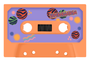
I first created 3 playlists of 4 songs. Then using pinterest inspirations of vintage cassette tapes, I drew each stage: cassette base, cassette sticker, cassette detail using procreate. I illustrated specific combinations of these cassettes to equate to a certain playlist and I drew the details to correspond with the overall music vibe and aesthetic: (see below: 1) result1, 2) result2, 3) result3). As mentioned in my user-testing documentation section,  I wanted to create an animation of the cassette tape rolling when users entered the final stage: music playing. The only plausible way was to create a gif file containing such animation. Because there are 3 choices for each 3 stages and 3 different combinations users could select, it meant I had to create animations for a total of 27 cassettes, hence why it was so time consuming.

PROCESSES – P5.JS:
Essentially both coding experiences were one I do not want to remember… the endless bug fixes, the endless error messages on the console, it was just incredibly stressful. However the code that evoked the most stress and hence, I’m most proud of was attributing the corresponding gif files to every possible indices user could end up with – likewise with creating the cassette animations, there were 27 different combinations. This meant that the program had to store the index chosen at each stage and use this information to call upon a gif file with the corresponding index. This was one of those sections that took 7+ hours to debug and code. I didn’t know where to start and how, so, like I always did with previous assignments, I began researching and looking for codes that fulfilled similar instances on google. Then came the experimentation and checking using console.log. Through this I was able to learn syntax I had never encountered before and this acted as a sort of revelation for me. Here is the relevant code section:

//
const gifFilenameMap = { //attributing gif file pathway to user selected indices
//for cassetteBase[0]
  "0_0_0": "gifs/result1_prpl1.gif",
  "0_0_1": "gifs/result1_prpl2.gif",
  "0_0_2": "gifs/result1_prpl3.gif",
  "0_1_0": "gifs/result1_green1.gif",
  "0_1_1": "gifs/result1_green2.gif",
  "0_1_2": "gifs/result1_green3.gif",
  "0_2_0": "gifs/result1_grey1.gif",
  "0_2_1": "gifs/result1_grey2.gif",
  "0_2_2": "gifs/result1_grey3.gif",

//for cassetteBase[1]
  "1_0_0": "gifs/result2_prpl1.gif",
  "1_0_1": "gifs/result2_prpl2.gif",
  "1_0_2": "gifs/result2_prpl3.gif",
  "1_1_0": "gifs/result2_green1.gif",
  "1_1_1": "gifs/result2_green2.gif",
  "1_1_2": "gifs/result2_green3.gif",
  "1_2_0": "gifs/result2_grey1.gif",
  "1_2_1": "gifs/result2_grey2.gif",
  "1_2_2": "gifs/result2_grey3.gif",

//for cassetteBase[2]
  "2_0_0": "gifs/result3_prpl1.gif",
  "2_0_1": "gifs/result3_prpl2.gif",
  "2_0_2": "gifs/result3_prpl3.gif",
  "2_1_0": "gifs/result3_green1.gif",
  "2_1_1": "gifs/result3_green2.gif",
  "2_1_2": "gifs/result3_green3.gif",
  "2_2_0": "gifs/result3_grey1.gif",
  "2_2_1": "gifs/result3_grey2.gif",
  "2_2_2": "gifs/result3_grey3.gif",
};

//generates gif filename based on indices of selected cassette components
function generateGifFilename(baseIndex, stickerIndex, detailIndex) {
  return gifFilenameMap[`${baseIndex}_${stickerIndex}_${detailIndex}`]; //generating filename using map => e.g., 2_1_0
}

function determineResult() {
...
//generating filename (e.g., "1_2_3") based on indices of selected components
  const gifFilename = generateGifFilename(selectedBaseIndex, selectedStickerIndex, selectedDetailIndex);
  gifElement = createImg(gifFilename, "selectedGif"); // displaying selected gif on canvas
  gifElement.size(imageWidth, imageHeight);
  gifElement.position(imagePosition.x, imagePosition.y);
}

PROCESSES – ARDUINO + SERIAL COMMUNICATION:
Serial communication was one I had the most issues with. I used the existing serial communication code (in mang’s lecture notes) for both arduino and p5.js and altered it around my main piece of code however, problem 1) there seemed to be issues with p5.js and arduino exchanging data, hence it was impossible to know whether the physical wiring of the components on the breadboard was the problem or whether it was the code itself that was causing issues. 2) I continually experienced error messages stating that there was a network error hence I was unable to connect to a serial port. Both cases required patience, calmness and perseverance and through this it was engrained into me again the importance of console logging when debugging faulty code. At the start, I wasn’t able to understand the serial communication code that was provided but after the completion of my final project, everything kind of clicked into place.

Regarding attributing functions to the physical components: 2 push buttons and a potentiometer, I was also having major problems with applying my desired functions: play/pause, skip forward, skip backward, to the push buttons. Mapping the volume to the potentiometer value was really easy as something like it had already been done for the serial communication assignment. For the rest, it was a nightmare. I think it was the structure of the code and the specific manner in which I coded that caused so many breakdowns and errors. In the end I was incredibly short for time and so was forced to compensate and only code 1) resetToInitialState, 2) skip forward on loop. when coding for the function: resetToInitialState, 2 problems occurred: 1) gif image appearing over initial state, 2) sound continuing to play regardless of being set to its initial state. With extensive experimentation, I realised that creating new variables to keep track of the states of both the gif and sound was the most simplest and most rational solution – here is the relevant code:

let gifElement; (ADDED) 

//within function determineResult() 
if (gifElement) { (ADDED) 
  gifElement.remove(); //remove existing gifElement if it exists 
} 

const gifFilename = generateGifFilename(selectedBaseIndex, selectedStickerIndex, selectedDetailIndex); 
gifElement = createImg(gifFilename, "selectedGif"); // displaying selected gif on canvas (ADDED) 
gifElement.size(imageWidth, imageHeight); (ADDED) 
gifElement.position(imagePosition.x, imagePosition.y); (ADDED) 

/////////////////////////////////////////////////////////////////////////////////////
let shouldPlayNextSound = true; //(ADDED) 

//within function playNextSound()
if (shouldPlayNextSound) { //(ADDED)
  currentSoundIndex++; // increment sound index
  if (currentStage === 4 && currentSoundIndex >= result1.length) {
    determineResult();
    currentSoundIndex = 0; //reset to the beginning if end is reached
  }
}

//within function resetToInitialState()
shouldPlayNextSound = false; //disable skip function (ADDED)

//stopping all currently playing sounds
for (let i = 0; i < result1.length; i++) {
result1[i].stop();
}
for (let i = 0; i < result2.length; i++) {
result2[i].stop();
}
for (let i = 0; i < result3.length; i++) {
result3[i].stop();
}
shouldPlayNextSound = true; //enable skip function (ADDED)

FINAL REFLECTIONS + FUTURE IMPROVEMENTS:
Whilst it was the most nerve wrecking, anxiety inducing overall experience, since persisting bugs were fixed the day of the IM show, I was quite proud of what I have completed. Whilst the coding aspect of this project was beyond challenging, I can’t deny that it was lowkey fun at the same time – creating a project that involves my passion. To me, it certainly felt like a large leap in the level of difficulty, compared to my midterm project, and this was more so why I am proud of the finished result. For future improvements on the project, perhaps there could be a personality test which based on your selected answers allocates you to a specific design for each stage of the cassette customisation. This way the experience maintains for longer. I also think it builds more excitement and anticipation as to what cassette you’ll end up with. Improvements for the physical aspect of the project would be to build a radio with more extensive functions, like originally planned.

Regarding improvements for future IM projects, I am incredibly motivated to put thought into the building of an exterior because that, at the end of the day, is what can elevate user experience. Since it was my first time both showcasing and attending an IM show, I experienced somewhat of an epiphanous moment. In future classes I will be more mindful in creating a more immersive user experience that is able to appeal to a wider body of people, because whilst mine did have some sort of user experience, it was more so stagnant with limited interaction compared to the other projects that were showcased. Overall I think it was an excellent opportunity to understand the fundamentals of what Interactive Media embodies and it has further propelled my motivation to learn in depth creative coding.

week 11&12 – (final project) preliminary concept | idea finalization | user testing

PRELIMINARY CONCEPT:
I wanted to do some brainstorming regarding the concept of my final project. I wanted to do something that wasn’t too ambitious (considering the myriad of deadlines as a result of finals week and the limited time constraints). I think because I couldn’t think of a theme, ideas were very vast which didn’t help. After some major considerations and scrapping of multiple ideas, I came to the conclusion that I would want to build off on my midterm project to create a physical radio that is controllable through i.e., buttons, potentiometer, power switch. Output would be digital and input would be both digital and physical.

FINALIZED CONCEPT:
I thought creating a purely physical radio with a digital output would not be enough interactivity or at least a meaningful interaction, hence I wanted to perpetuate intimacy. I love music and (to me) what is more intimate than sharing your favourite playlists/ artists with others? I decided to make my final project a 2-part: 1) determine corresponding mood/ personality through personalizing their own cassette tape, 2) according to results, a playlist of 4 songs would be curated – this way there is more intimate and meaningful back and forth. Essentially it would work like those buzzfeed quizzes except physical input via push buttons are possible.

Total physical components would include 3 push buttons and a potentiometer for volume control. My arduino program will read the potentiometer value and buttons’/switch’s state and send the information to p5.js via serial communication. When p5.js receives information about the button’s push state, it will call upon its corresponding function, i.e., pause/play, skip forward/ backward. I will use the mapping function to map the potentiometer value to the volume so that whenever the potentiometer is toggled, p5.js will continuously receive its p value and adjust the volume accordingly. With regards to my p5 program design, I intend to have a cassette displayed in the middle with “select” and arrows buttons. Since users will select designs for each of the 3 stages, the “select” button will store user choices in a separate variable so as to assign a “result1/2/3” playlist. Although undecided, I intend to have a separate display screen for when the recommended playlist sounds to indicate the change of focus from p5 to the actual physical components.

FINAL PROJECT – Photo Booth : Design your ID card

CONCEPT

As I mentioned before, for my final project I decided to create an engaging experience for anyone on our campus at NYUAD to design their new ID card. This is supposed to tackle two aims: 1) bring joy and fun to people who are using the program; 2) allow people to be creative and design a card that suits their character.

At the very beginning, during the development of the idea, one of my classmates mentioned that my idea reminded them of a photo booth. This became the main concept of the experience. I constructed a real photo booth, to which people can come, sit down and take their selfies, as they like. If they do not like the picture, they can take it again as many times as they want, until they are satisfied with the result. So, this project would address the issue of dissatisfaction with ID card photos through the feature of capturing their images in real-time.

Then, participants can write whatever name they want on their new ID card. Sometimes people do not like the name that appears on their passport, which unfortunately they cannot change. However, in this project, I am giving them this opportunity.

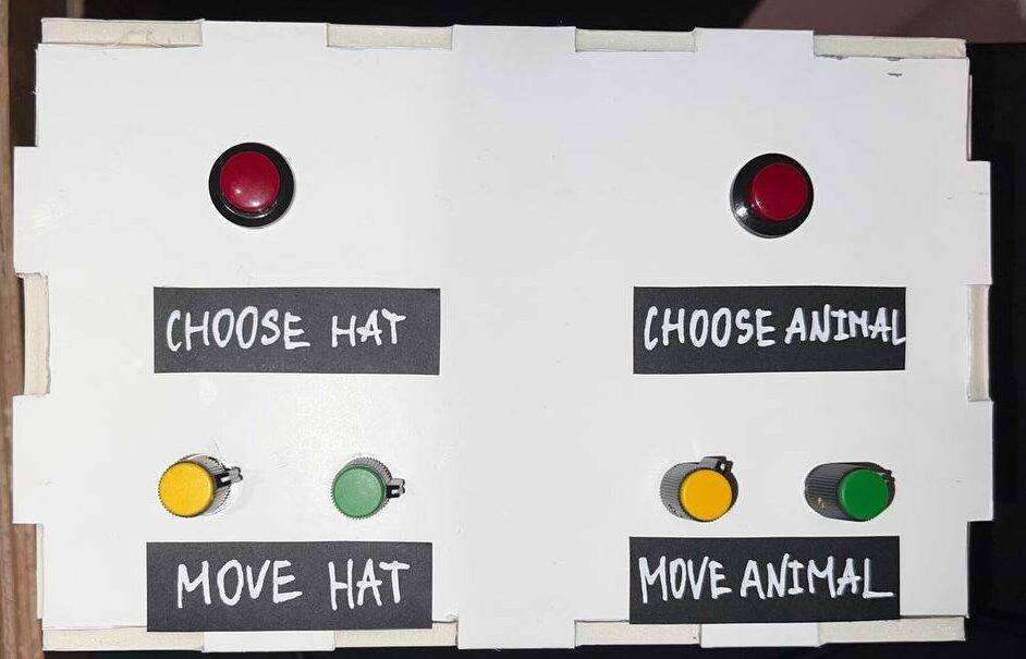
Then, the fun part begins. Users can choose from a variety of images to be displayed on their ID. I have two categories: ANIMALS and HATS. They can choose whatever image they want by pressing buttons. Moreover, they can position them anywhere on their ID badge. This aims to enhance the individuality of their IDs.

Finally, they can save an image of their ID, which I will, of course, send to them afterward. So, this project seeks to not only address practical concerns but also provide a unique and enjoyable experience for users.

IMPLEMENTATION
Interaction Design 

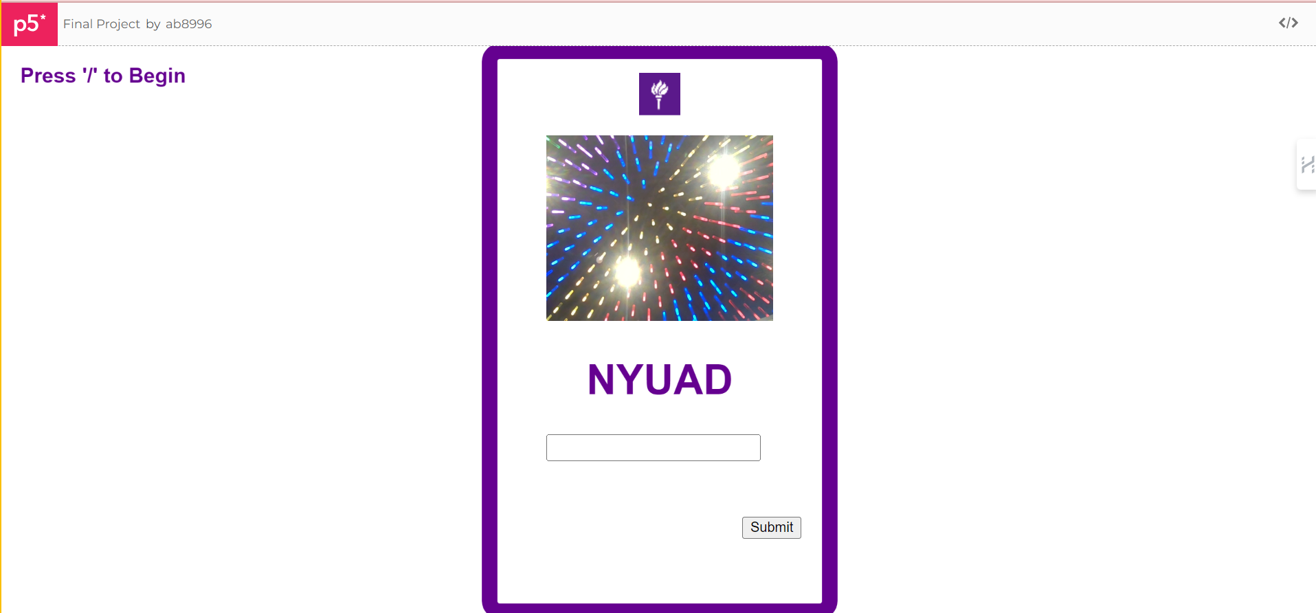
This is a P5 setup in the beginning:

After you connect to the port by pressing the “/” key, and you press ENTER to take a snapshot, two images appear (animal and hat images).

You can go through an array of images by pressing the red buttons and choosing the hat and animal that you like. Further, you can adjust their position with potentiometer knobs. You can write your name in the input text box and SUBMIT it by clicking the button, so it appears as usual text on the ID badge. Finally, if you are satisfied with everything, you can click the CAPTURE button and save the ID badge.

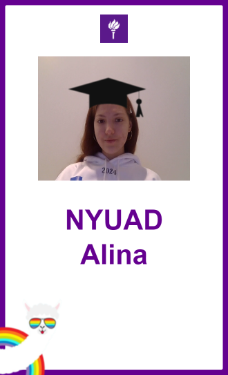
The final ID badge image looks like this:

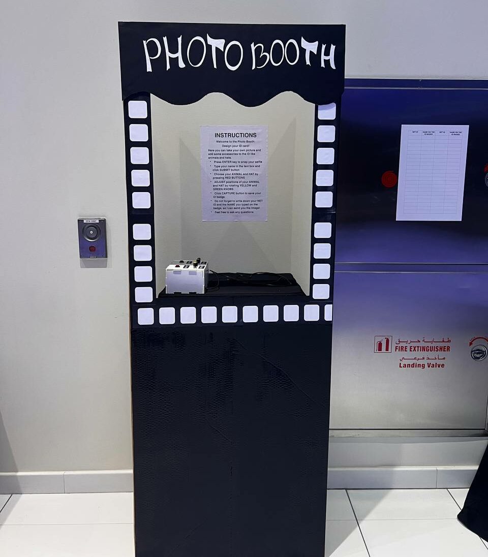
Set up during the show:

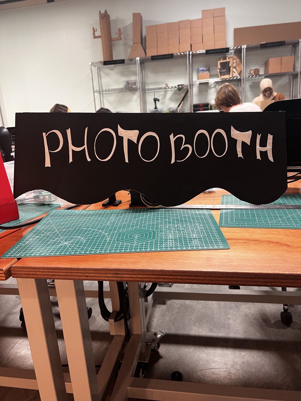
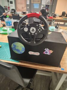
I have developed my concept further and designed a photobooth from cardboard. I printed out instructions and the table for people to fill in (where they would write their name and net ID, so I can send them the image of the ID badge later). I have designed this box from large cardboard pieces that I found in the lab. Painted the front with black acrylic paint and printed a design that reminds me of the film. 

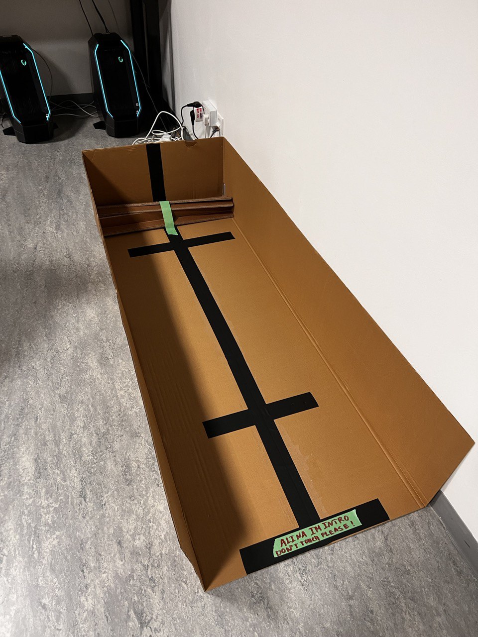
Process:

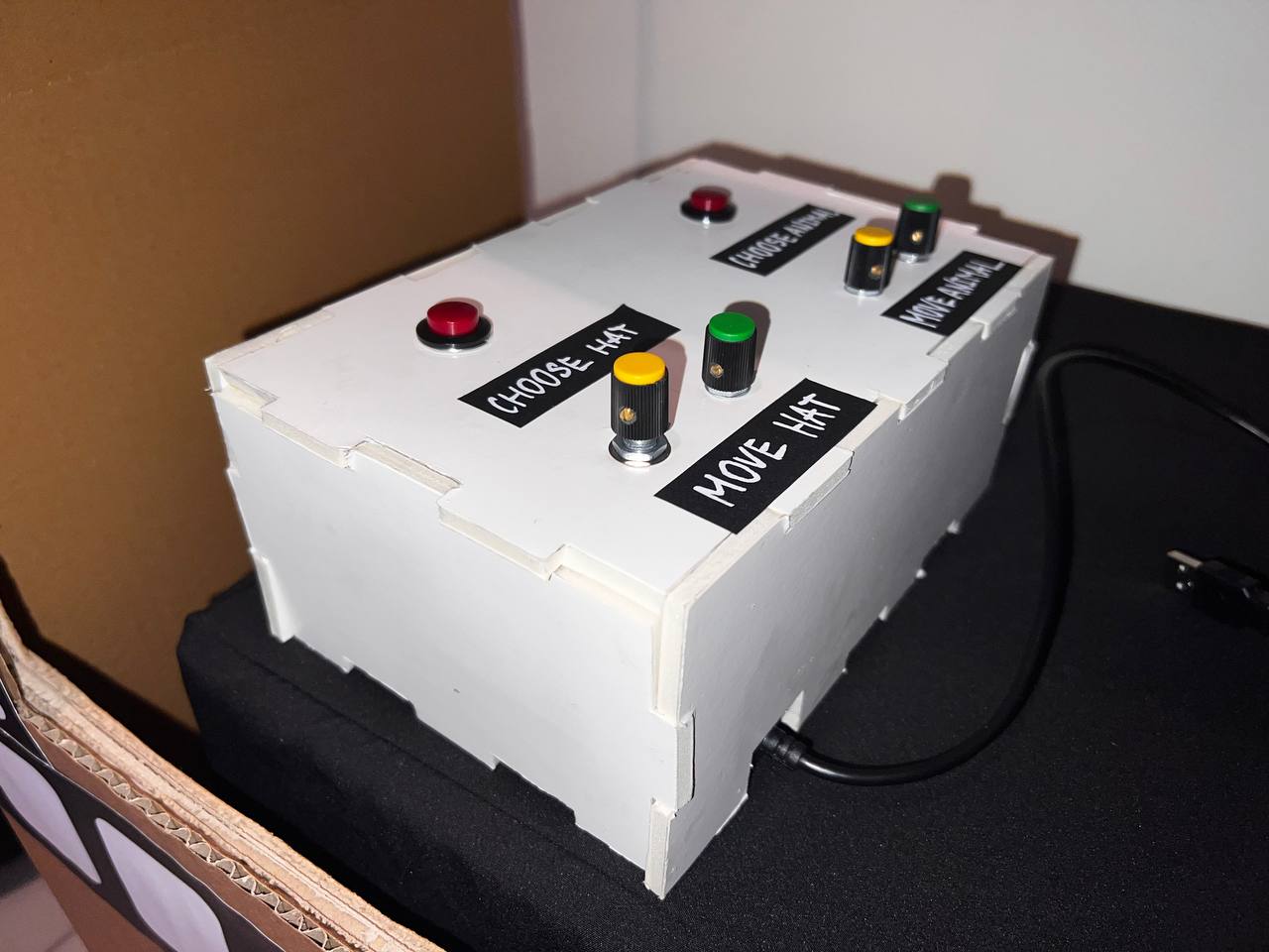
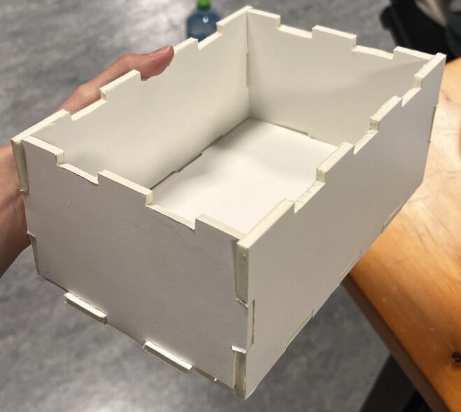
Another part of my project is a small white box that I built from foamboard, which holds two red buttons, 4 potentiometer knobs (yellow for the X axis and green for the Y axis), and labels for them. I have designed this box in the Maker Case.  Then I used a ruler and box cutter to cut all the parts and assemble them. They fit nicely, but I additionally used some glue to be sure the box can hold the pressure from pressing buttons and rotating knobs. 

Process:

During the process of building these parts, the biggest challenge was cutting the elements. I did not have an opportunity to use a laser cutter, therefore I spent lots of time cutting and taping everything by hand.

P5 code

Most of the time was spent setting up the P5 sketch. What does it do? The P5 program starts with a display of an ID badge. I design these with primitive rectangular shapes and text. I wanted to include instructions on the screen. however, I did not want to overcomplicate the appearance of the sketch, so I decided to do it on an A3 paper. However, as I noticed not many were reading instructions presented behind the laptop, therefore, it would be better to present them on the screen.

On the P5, participants were presented with a live video which is the size of a snapshot they are about to make. As they press ENTER, the snapshot selfie replaces the live video. This was a very challenging part of the code. However, with some help, I was able to do this. Here is the portion of the code that I used as an example:

let capture;

function setup() {
  createCanvas(500, 500);
  capture = createCapture(VIDEO);
  capture.hide();
}

function draw() {
  let aspectRatio = capture.height/capture.width;
  
  image(capture, 0, 0, width, width * aspectRatio);
  filter(INVERT);
}

As soon as the photograph is taken, and if it is taken,  the signal to Arduino is sent, so it can now send communication to P5. P5 then acts as a receiver and displays different images of hats and animals. Moreover, participants can type their name in the input box and submit it to be displayed on the screen. Finally, by clicking capture they can save their ID cards. This is all done with built-in boxes and buttons in P5.

It was hard to figure out the logic that I wanted my program to have. But finally, I managed to do a set of nested if statements which I am very proud of. This is a part of the code that allows you to go in an array of images and select their position.

 if (snapshot) {
    // Display a captured selfie in place of the live video
    // resizing to the same parameters as video

    image(snapshot, width / 2, height / 2 - 100, 220, 180);

    // A nested if statement:
    // if -1 then no hat image is selected, otherwise the statement is true.
    // If a hat image is selected, then display the image at the index selectedHat from the array of hatImages.
    // The image is placed at coordinates (hatX, hatY).

    if (selectedHat !== -1) {
      image(hatImages[selectedHat], hatX, hatY);
    }

    // A nested if statement:
    // if -1 then no animal image is selected, otherwise the statement is true.
    // If an animal image is selected, then display the image at the index selectedAnimal from the array of animalImages.
    // The image is placed at coordinates (animalX, animalY).

    if (selectedAnimal !== -1) {
      image(animalImages[selectedAnimal], animalX, animalY);
    }
  }
}
Final Code for P5- embedded sketch: 
Arduino Code

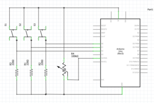
Setting up the Arduino code was pretty easy. I used only the information we learned in class.   The code consists of the declaration of 2 buttons, 4 potentiometers, and their states. The state of each button and the potentiometer is read and sent to p5.  The part that I am proud of is mapping the potentiometer values to the desired range of the canvas. This was a very important part of the Arduino code because, with this, users were able to adjust the position of hat and animal images.

  • When pressing the HAT button, which is a digital input on pin 2, participants will see an image of a hat. They can choose their hat by pressing the button again.
  • Then participants will need to adjust the position of a hat using 2 potentiometers that also operate on 2 potentiometers, which are analog inputs and located on pins A0 and A1.
  • They can also do the same actions to choose their favorite animal by pressing the ANIMAL button. They can also select an appropriate location using two potentiometers, which are analog inputs and located on pins A2 and A3.
Final code for Arduino: 
const int buttonHatPin = 2;        // Pin for the hat button
const int buttonAnimalPin = 3;     // Pin for the animal button
const int potentiometerHatXPin = A0;  // Pin for the X-axis potentiometer for hat
const int potentiometerHatYPin = A1;  // Pin for the Y-axis potentiometer for hat
const int potentiometerAnimalXPin = A2;  // Pin for the X-axis potentiometer for animal
const int potentiometerAnimalYPin = A3;  // Pin for the Y-axis potentiometer for animal

int buttonHatState = 0;       // Current state of the hat button
int buttonAnimalState = 0;    // Current state of the animal button
int potentiometerHatXValue = 0;  // Current value of the X-axis potentiometer hat
int potentiometerHatYValue = 0;  // Current value of the Y-axis potentiometer hat
int potentiometerAnimalXValue = 0;  // Current value of the X-axis potentiometer animal

int potentiometerAnimalYValue = 0;  // Current value of the Y-axis potentiometer animal

void setup() {
  Serial.begin(9600);               // Initialize the serial communication
  pinMode(buttonHatPin, INPUT);     // Setting up the button pin as input
  pinMode(buttonAnimalPin, INPUT);  // Setting up the button pin as input


  // START THE HANDSHAKE TO SEND 6 VALUES FROM ARDUINO TO P5
  while (Serial.available() <= 0) {
    digitalWrite(LED_BUILTIN, HIGH);  // on/blink while waiting for serial data
    Serial.println("0,0,0,0,0,0");    // send a starting message
    delay(300);                       // wait 1/3 second
    digitalWrite(LED_BUILTIN, LOW);
    delay(50);
  }
}

void loop() {
  buttonHatState = digitalRead(buttonHatPin);           // Read the state of the hat button
  buttonAnimalState = digitalRead(buttonAnimalPin);     // Read the state of the animal button
  potentiometerHatXValue = analogRead(potentiometerHatXPin);  // Read the value of the X-axis potentiometer for hat image
  potentiometerHatYValue = analogRead(potentiometerHatYPin);  // Read the value of the Y-axis potentiometer for hat image
  potentiometerAnimalXValue = analogRead(potentiometerAnimalXPin);  // Read the value of the X-axis potentiometer for animal image
  potentiometerAnimalYValue = analogRead(potentiometerAnimalYPin);  // Read the value of the Y-axis potentiometer for animal image


  // Map the potentiometer values to the desired range
  int hatX = map(potentiometerHatXValue, 0, 1023, 0, 900);  // Map X-axis potentiometer value to the canvas width
  int hatY = map(potentiometerHatYValue, 0, 1023, 0, 900);  // Map Y-axis potentiometer value to the canvas height

  int animalX = map(potentiometerAnimalXValue, 0, 1023, 0, 900);  // Map X-axis potentiometer value to the canvas width
  int animalY = map(potentiometerAnimalYValue, 0, 1023, 0, 900);  // Map Y-axis potentiometer value to the canvas height

  // Send the button states and potentiometer values to p5.js
  Serial.print(buttonHatState);
  Serial.print(",");
  Serial.print(buttonAnimalState);
  Serial.print(",");
  Serial.print(hatX);
  Serial.print(",");
  Serial.print(hatY);
  Serial.print(",");
  Serial.print(animalX);
  Serial.print(",");
  Serial.println(animalY);

  delay(100);  // Delay for stability
}
Communication between Arduino and P5
The communication is one-sided in my project. I am sending all 6 signals from Arduino to P5 (2 buttons states as digital inputs and 4 potentiometers states as analog inputs). From P5 to Arduino it is an empty line communication which I ignore. Although I planned to have communication from P5 to Arduino as a sound buzzer that would remind me of a snapshot sound, due to time constraints I decided not to do it. This turned out to be the best decision because it was very loud during the showcase and other projects that had sounds were very hard to hear.
FUTURE IMPROVEMENTS AND REFLECTIONS
What are some aspects of the project that you’re particularly proud of?

Overall, I am very proud of the fact that I was able to do this project at all. Given the fact that I have never coded before, and I was not very successful in my midterm project, I am very happy that I was able to finish the final project and it was functioning nicely during the 2 hours of the IM showcase.

I am very proud of the fact that I now understand how to program and be able to use the knowledge that I learned in class to build my own program.
I am very proud that my project was successful and that I was able to make an interesting, engaging, and fun experience for all age categories that were present during the showcase. I believe that finalizing my concept by building a huge Photo Booth was the key as it attracted the attention of the users. They wanted to come closer and see what was going on. My users were professors, students, and even kids. They all enjoyed the cute hats and animal images that I chose and were happy that I would send them their ID cards.
What are some areas for future improvement?
I feel that this project that even be taken to the next level. Maybe installing such kind of a photobooth for everybody’s use on campus is a potential. Instead of saving a picture, I would make this a printable ID badge, just like in the bank office where they print bank cards.
If I would go back and redo some aspects, I would add lights that users can adjust and some kind of filters to enhance their photographs. I would probably use a usual camera, so the quality of the picture taken is much better.
Moreover, during the showcase, I was asked if it was possible to resize the image of a hat. Next time I would add a potentiometer to do this. Moreover, I would flip a camera, so it reminds me of an actual picture taken. Most girls found this to be problematic.
ACKNOWLEDGEMENT AND SOURCES
My professor Michael Shiloh helped me a lot during this process. I am grateful for his emotional support and for debugging the program with me at every step!
Thanks to Professor Aya for explaining to me how to resize and capture a video as an image!
And thanks to Professor Mang for identifying that my potentiometers were not functioning and for providing me with new ones!
I mainly used the P5 Reference page. It is very very helpful!
Links to images I used:
Animals:
Hats:

Final Project: GALAXIAN 2.0

Concept

During my first semester, I made a game called “Galaxian” for one of my final projects. Galaxian was a classic, straightforward space shooting game where players could control the movement of a spaceship on screen across the x axis. Essentially, they could only use left and right arrow keys to move the ship in a different direction. The aliens on screen were static and the user had to shoot lasers at them to kill them.

The simplicity of Galaxian laid the groundwork for  the birth of “Galaxian 2.0.” The initial project became a muse and inspired me to envision a more immersive and evolved gaming experience. In this sequel, I wanted to elevate the gaming dynamics with a physical controller.

User testing

link to video demonstration: https://youtu.be/hGPZssA0Q-Q

Since the menu contained all the necessary information, there wasn’t much explanation required from my end. However, a notable observation was that users often struggled to grasp the concept of a “moving” spaceship in the second level.

Following the initial user testing phase, two crucial insights emerged:

  • It was essential to enhance the distinction between alien and spaceship lasers for better user comprehension.
  • The second level needed adjustments to make it slightly easier.
P5js Code
let score = 0;
let spaceship;

//images and menus
let spaceshipImage;
let bg;
let gamewin;
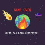
let earthDestroy;
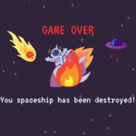
let shipDestroy;
let gamebg;
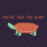
let tooSlow;

let laserSound;
let explosionSound;
let potVal = 450;
let shoot = 0; 
let lastShootTime = 0;
let shootInterval = 200;
let startTime;
let gameDuration = 30 * 1000;
let isSerialConnected = false;
let lasers = [];
let level = 1;
let transitionScreenVisible;
let asteroids = [];
let asteroidSpeed = 2;
let damage = 0;
let maxDamage = 10;
let asteroidImage;

//LEVEL 2
let instructionsMenu;
let alienImage;
let aliens = [];
let alienSpeed = 2;
let alienLasers = [];
let aliensHitGround = 0;
let level2StartTime;

let bgMusic; // Background music

function preload() {
  spaceshipImage = loadImage("images/spaceship.png");
  asteroidImage = loadImage("images/asteroid.png");
  alienImage = loadImage("images/alien.png");
  bg = loadImage("images/bg.png");
  earthDestroy=loadImage("images/earthdestroy.png");
  shipDestroy = loadImage("images/spaceshipdestroy.png");
  instructionsMenu = loadImage("images/level2instructions.png");
  tooSlow = loadImage("images/tooslow.png");
  gamebg = loadImage("images/gamebg.png");
  gamewin = loadImage("images/gamewin.png");
  
  bgMusic = loadSound("sounds/bgmusic.mp3");
  laserSound = loadSound("sounds/shoot.mp3");
  explosionSound = loadSound("sounds/explosion.mp3");
}

function setup() {
  createCanvas(displayWidth,displayHeight);
  spaceship = new Spaceship();
  // Initialize aliens
  for (let i = 0; i < 3; i++) {
    let alien = new Alien();
    aliens.push(alien);
  }
  // Start playing background music
  // bgMusic.loop();
}
function draw() {
  background(25);
  // console.log(shoot);

  if (level === 1) {
    displayLevel1();
  } else if (level === 2) {
    if (transitionScreenVisible) {
      showLevelTransitionScreen(2);
    } else {
      displayLevel2();
    }
  }
}

function displayLevel1() {
  textSize(20);
  image(gamebg, width/2, height/2, width, height);
  if (isSerialConnected) {
    bgMusic.pause();
    let elapsedTime = millis() - startTime;
    let remainingTime = max(0, gameDuration - elapsedTime);

    // Check for collisions with user laser and asteroids
    for (let i = asteroids.length - 1; i >= 0; i--) {
      asteroids[i].display();
      asteroids[i].update();

      for (let j = lasers.length - 1; j >= 0; j--) {
        if (asteroids[i].hits(lasers[j])) {
          score++;
          asteroids.splice(i, 1); // Remove the asteroid
          explosionSound.play();
          lasers.splice(j, 1); // Remove the laser
        }
      }
    }

    // Generate new asteroids
    if (frameCount % 60 === 0) {
      let asteroid = new Asteroid();
      asteroids.push(asteroid);
    }
    
    spaceship.display();
    spaceship.update();
    updateLasers();
    
    fill(220);
    text("Score: " + score, 20, 30);
    text("Remaining Time: " + (remainingTime / 1000).toFixed(2) + "s", 20, 60);

    // Check if any asteroid hits the ground
    for (let i = asteroids.length - 1; i >= 0; i--) {
      if (asteroids[i].hitsGround()) {
        // console.log(damage);
      }
    }

    if (damage > maxDamage) {
      gameOver();
      return;
    }

    if (remainingTime <= 0) {
      gameOver();
    }

    // Check if the user hits a score of 10 to move to Level 2
    if (score >= 10) {
      transitionScreenVisible = true;
      level = 2;
      // showLevelTransitionScreen(2);
    }
  } else {
    // bgMusic.play();
    image(bg, 0, 0, width, height);
  
  }
}

function showLevelTransitionScreen(nextLevel) {
  // bgMusic.play();
  image(instructionsMenu, width/2, height/2, width, height);
}

function mousePressed() {
  if (transitionScreenVisible) {
    // Start the next level
    asteroids = []; // Clear the asteroids array
    score = 0; // Reset the score
    damage =0;
    startTime = millis(); // Restart the timer
    transitionScreenVisible = false; // Hide the transition screen
  }
}

function displayLevel2() {
  image(gamebg, width/2, height/2, width, height);
  fill(255);
  textSize(32);
  textAlign(CENTER, CENTER);
  
  // Check if it's the first frame of Level 2
  if (!level2StartTime) {
    level2StartTime = millis();
  }

  // Calculate elapsed time
  let elapsedTime = millis() - level2StartTime;
  let remainingTime = max(0, 30 * 1000 - elapsedTime);

  // Display timer & score
  textSize(20);
  text("Score: " + score, width / 2, 70 )
  text("Time: " + (remainingTime / 1000).toFixed(2) + "s", width / 2, 30);
  text("Alien Invasions: "+aliensHitGround, width/2, 50);

  // Check if the time is up
  if (remainingTime <= 0) {
    // text("Time's up!", width / 2, height / 2);
    gameOver();
    return;
  }

  // Update and display aliens
  for (let i = aliens.length - 1; i >= 0; i--) {
    aliens[i].update();
    aliens[i].display();

    // Check if the alien should shoot a laser
    if (random(1) < 0.01) {
      aliens[i].shootLaser(spaceship);
    }
    
    // Check if the alien has hit the ground
    if (aliens[i].y + aliens[i].height > height) {
      aliens.splice(i, 1);
      aliensHitGround++;
      console.log(aliensHitGround);

      // Check if more than 10 aliens hit the ground
      if (aliensHitGround > 100) {
        // text("Earth destroyed!!!1", 200, 200);
        gameOver();
        return;
      }
    }
  }

  // Check for collisions spaceship lasers with aliens
  for (let i = lasers.length - 1; i >= 0; i--) {
    for (let j = aliens.length - 1; j >= 0; j--) {
      if (lasers[i].hits(aliens[j])) {
        // Handle laser hit on aliens
    
        // score++;
        aliens.splice(j, 1); // Remove the alien
        explosionSound.play();
        lasers.splice(i, 1); // Remove the laser
        score++;
        
        // Check if the user wins the game
        if (score >= 10 && remainingTime > 0) {
          gameWin();
        }
        
        break; // Exit the inner loop after a collision is found
      }
    }
  }
  //check for collisions between aliens laser and the spaceship
  for (let i = alienLasers.length - 1; i >= 0; i--) {
    if (alienLasers[i].hits(spaceship)) {
      // Handle collision with spaceship
      
      // text(("detection!"), 100, 100);
      damage++;
     
      alienLasers.splice(i, 1); // Remove the alien laser
      if (damage > maxDamage){
        gameOver();
      }
    }
  }

  // Display and update alien lasers
  for (let i = alienLasers.length - 1; i >= 0; i--) {
    alienLasers[i].display();
    alienLasers[i].update();

    if (alienLasers[i].offscreen()) {
      alienLasers.splice(i, 1);
    }
  }

  // Check if there are no more aliens, then respawn a new set
  if (aliens.length === 0) {
    for (let i = 0; i < 3; i++) {
      let alien = new Alien();
      aliens.push(alien);
    }
  }

  spaceship.display();
  updateLasers();
  spaceship.updateLevel2();
}

function gameWin() {
  // Display the game win image or perform other actions
  image(gamewin, width / 2, height / 2, width, height);
  noLoop(); // Stop the draw loop to freeze the game
  mousePressed = restartGame;
}

class Asteroid {
  constructor() {
    this.radius = random(20, 40);
    this.x = random(this.radius, width - this.radius);
    this.y = -this.radius;
    this.hitGround = false; //track if the asteroid has hit the ground
  }

  display() {
    imageMode(CENTER);
    image(asteroidImage, this.x, this.y, this.radius * 2, this.radius * 2);
  }

  update() {
    this.y += asteroidSpeed;
  }

  hits(laser) {
    let d = dist(laser.x, laser.y, this.x, this.y);
    return d < this.radius + 2;
  }

  hitsGround() {
    if (this.y + this.radius > height && !this.hitGround) {
      damage++;
      this.hitGround = true;
    }
    return this.y + this.radius > height;
  }
}

class Spaceship {
  constructor() {
    this.width = 70;
    this.height = 70;
    this.x = width / 2 - this.width / 2;
    this.y = height - this.height;
    this.speed = 5;
    this.rotation = 0; // Initial rotation angle
  }

  display() {
    push();
    translate(this.x + this.width / 2, this.y + this.height / 2);
    rotate(radians(this.rotation));
    imageMode(CENTER);
    image(spaceshipImage, 0, 0, this.width, this.height);
    pop();
  }

  update() {
    if (keyIsDown(UP_ARROW)) {
      this.y -= this.speed;
    } else if (keyIsDown(DOWN_ARROW)) {
      this.y += this.speed;
    }

    // Ensure the spaceship stays within the bounds of the canvas height
    this.y = constrain(this.y, 0, height - this.height);

    // Map potVal from the range 0-1023 to -90 to 90 for rotation
    this.rotation = map(potVal, 966, 12, -90, 90);
    // FOR WHEEL: potVal, 966, 12, -90, 90

    // Check if enough time has passed since the last shoot
    if (shoot === 1 && millis() - lastShootTime >= shootInterval) {
      // Shoot a laser
      let laser = new Laser(
        this.x + this.width / 2,
        this.y + this.height / 2,
        this.rotation - 90
      );
      lasers.push(laser);
      lastShootTime = millis(); // Update the last shoot time
      // Play the laser sound effect
      laserSound.play();
    }
  }
  updateLevel2() {
    // Spaceship movement in the direction it is pointing
    this.rotation = map(potVal, 966, 12, -180, 180);
    let spaceshipDirection = p5.Vector.fromAngle(radians(this.rotation - 90)); // Subtract 90 to align with the forward direction
    this.x += spaceshipDirection.x * this.speed;
    this.y += spaceshipDirection.y * this.speed;

    // Ensure the spaceship stays within the bounds of the canvas
    this.x = constrain(this.x, 0, width - this.width);
    this.y = constrain(this.y, 0, height - this.height);

    // Check if enough time has passed since the last shoot
    if (shoot === 1 && millis() - lastShootTime >= shootInterval) {
      // Shoot a laser
      let laser = new Laser(
        this.x + this.width / 2,
        this.y + this.height / 2,
        this.rotation - 90
      );
      lasers.push(laser);
      lastShootTime = millis(); // Update the last shoot time
      // Play the laser sound effect
      laserSound.play();
    }
  }
}

class Alien {
  constructor() {
    this.width = 50;
    this.height = 50;
    this.x = random(width - this.width);
    this.y = -this.height;
    this.speedX = random(-1, 1) * alienSpeed;
    this.speedY = random(0.5, 1) * alienSpeed;
  }

  display() {
    imageMode(CENTER);
    image(
      alienImage,
      this.x + this.width / 2,
      this.y + this.height / 2,
      this.width,
      this.height
    );
  }

  update() {
    this.x += this.speedX;
    this.y += this.speedY;

    // Bounce off the walls
    if (this.x < 0 || this.x + this.width > width) {
      this.speedX *= -1;
    }

    // Wrap around vertically
    if (this.y > height) {
      this.y = -this.height;
      this.x = random(width - this.width);
      this.speedX = random(-1, 1) * alienSpeed;
      this.speedY = random(0.5, 1) * alienSpeed;
    }
  }
  shootLaser(spaceship) {
    // Calculate the angle between the alien and the spaceship
    let angle = atan2(spaceship.y - this.y, spaceship.x - this.x);

    // Shoot an alien laser in the calculated angle
    let alienLaser = new AlienLaser(
      this.x + this.width / 2,
      this.y + this.height / 2,
      degrees(angle)
    );
    alienLasers.push(alienLaser);
  }

  hits(laser) {
    let alienCenterX = this.x + this.width / 2;
    let alienCenterY = this.y + this.height / 2;

    // Check if the laser is within the bounding box of the alien
    return (
      laser.x > this.x &&
      laser.x < this.x + this.width &&
      laser.y > this.y &&
      laser.y < this.y + this.height
    );
  }
}

class AlienLaser {
  constructor(x, y, rotation) {
    this.x = x;
    this.y = y;
    this.speed = 5;
    this.rotation = rotation;
  }

  display() {
    push();
    translate(this.x, this.y);
    rotate(radians(this.rotation));
    stroke(0, 255, 0);
    strokeWeight(2);
    line(0, 0, 20, 0); 
    pop();
  }

  update() {
    this.x += this.speed * cos(radians(this.rotation));
    this.y += this.speed * sin(radians(this.rotation));
  }

  offscreen() {
    return this.x > width || this.x < 0 || this.y > height || this.y < 0;
  }
  hits(spaceship) {
    let d = dist(
      this.x,
      this.y,
      spaceship.x + spaceship.width / 2,
      spaceship.y + spaceship.height / 2
    );
    return d < (spaceship.width + spaceship.height) / 4;
  }
}

class Laser {
  constructor(x, y, rotation) {
    this.x = x;
    this.y = y;
    this.speed = 10;
    this.rotation = rotation;
  }

  display() {
    push();
    translate(this.x, this.y);
    rotate(radians(this.rotation));
    stroke(255, 0, 0);
    strokeWeight(2);
    line(0, 0, 20, 0); 
    pop();
  }

  update() {
    this.x += this.speed * cos(radians(this.rotation));
    this.y += this.speed * sin(radians(this.rotation));
  }

  offscreen() {
    return this.x > width || this.x < 0 || this.y > height || this.y < 0;
  }
  hits(alien) {
    let d = dist(
      this.x,
      this.y,
      alien.x + alien.width / 2,
      alien.y + alien.height / 2
    );
    return d < (alien.width + alien.height) / 4; 
  }
}

function updateLasers() {
  for (let i = lasers.length - 1; i >= 0; i--) {
    lasers[i].display();
    lasers[i].update();

    if (lasers[i].offscreen()) {
      lasers.splice(i, 1);
    }
  }
}

function keyPressed() {
  if (key == " ") {
    // important to have in order to start the serial connection!!
    setUpSerial();

    isSerialConnected = true; // Update connection status
    startTime = millis(); // Start the timer when the connection is made
  }
  
  if (key === 'f' || key === 'F') {
    let fs = fullscreen();
    fullscreen(!fs);
  }
}

function readSerial(data) {
  // READ FROM ARDUINO HERE

  if (data != null) {
    let fromArduino = split(trim(data), ",");
    if (fromArduino.length == 2) {
      potVal = int(fromArduino[0]);
      shoot = int(fromArduino[1]);
      // console.log("val:");
      // console.log(shoot);
    }

    // SEND TO ARDUINO HERE (handshake)
    let sendToArduino = damage + "," + maxDamage + "\n";
    // console.log(damage);
    // console.log(maxDamage);
    writeSerial(sendToArduino);
  }
}
function gameOver() {
  noLoop(); // Stop the draw loop
  // Call a function from gameover.js to display the game over screen
  showGameOver();
}

// gameover.js

function showGameOver() {
//   // Implement your game over screen here
//   background(0); // Set background to black

//   fill(220);
  textSize(32);
  textAlign(CENTER, CENTER);
//   text("Game Over!", width / 2, height / 2 - 50);
  
  if (level===1){
    if (damage>maxDamage){
      image(earthDestroy, width/2,height/2, width, height);
      text("Your Score: " + score, width / 2, height-100);
    }
    else{
      image(tooSlow, width/2,height/2, width, height);
      text("Your Score: " + score, width / 2, height-100);
    }
  }
  
  else if(level ===2){
    if(aliensHitGround>10){ //greater than set value of invasions allowed
      image(earthDestroy, width/2,height/2, width, height);
      text("Your Score: " + score, width / 2, height-100);
    }
    else if(damage>= maxDamage){
      image(shipDestroy,width/2,height/2, width, height );
      text("Your Score: " + score, width / 2, height -100);
    }
    else{
      image(tooSlow, width/2,height/2, width, height);
      text("Your Score: " + score, width / 2, height-100);
    }
  }

  // Draw restart button
  fill(255);
  textSize(20);
  text("Click to Restart", width / 2, height -50);

  // Add event listener for the restart button
  mousePressed = restartGame;
}

function restartGame() {
  // Reload the page to restart the game
  location.reload();
}
Arduino code
const int ledPin = 2;  // Define the LED pin
const int ledPin2 = 3; // Define the LED pin
const int ledPin3 = 4; // Define the LED pin

void setup() {
  pinMode(ledPin, OUTPUT); // Set the LED pin as an output
  pinMode(ledPin2, OUTPUT); // Set the LED pin as an output
  pinMode(ledPin3, OUTPUT); // Set the LED pin as an output

  Serial.begin(9600);
  while (Serial.available() <= 0) {
    Serial.println("0,0");
    delay(300);
  }
}

void loop() {
  while (Serial.available()) {
    int damage = Serial.parseInt();
    int maxDamage = Serial.parseInt();
    if (Serial.read() == '\n') {
      // perform actions based on received data from p5
      int sensor = analogRead(A0);
      delay(5);
      int sensor2 = digitalRead(A1);
      delay(5);
      Serial.print(sensor);
      Serial.print(',');
      Serial.println(sensor2);

      // Check if damage is between 1 and 4
      if (damage <= 4) {
        digitalWrite(ledPin3, HIGH); // Turn on the LED at pin 3
      } else {
        digitalWrite(ledPin3, LOW); // Turn off the LED at pin 3
      }

      // Check if damage is between 5 and 7
      if (damage >= 5 && damage <= 7) {
        digitalWrite(ledPin2, HIGH); // Turn on the LED at pin 2
      } else {
        digitalWrite(ledPin2, LOW); // Turn off the LED at pin 2
      }

      // Check if damage is between 8 and maxDamage
      if (damage >= 8 && damage <= maxDamage) {
        digitalWrite(ledPin, HIGH); // Turn on the LED at pin 2
      } else {
        digitalWrite(ledPin, LOW); // Turn off the LED at pin 2
      }
    }
  }
}

Arduino -> P5js:

Arduino sends the potentiometer (inside the steering wheel) values to p5js. The p5js  code maps the values from the potentiometer meter to different rotation angles for the spaceship. In the first level, since the spaceship does not move around, the angle of rotation is limited to -90 to 90 degrees. In the next level since the spaceship moves continuously, it was important to ensure full rotation to allow movements in all direction. While implementing this, I realised since the steering wheel is a bit hard to move around and i found the minimum and maximum values for the potentiometer to be 12 – 966 therefore the mapping looks something like this:

this.rotation = map(potVal, 12, 966, -180, 180)

The switch button simply shoots a laser if the value sent from arduino is 1.

P5js -> arduino:

Additionally, I also added 3 leds health bars. P5js sends current “damage” to arduino and based on this value, the arduino code handles which led to light up using if conditions.

P5 sketch

Challenges

One of the challenges I faced was implementing the code for level 2 as I had to figure out how to ensure the aliens shoot in the direction of the moving spaceship. Initially, I had one lasers class that I was trying to use for both the spaceship and the aliens. I decided it would be a whole lot easier and cleaner if i made a separate class for aliens laser and that way implementing detection with the spaceship would be easier as well and it would be easier for users to differentiate between the two. With a separate alien laser class, I simply added a method that detects collision with the spaceship.

Another challenge for me was making the physical controller itself. I did not have any prior experience working with drills etc (other than the tool training) so it was a bit of a challenge at first. I also realised a lot of the led indicators were broken so I had to replace the LEDs in them myself.

Also, while working on the p5 code I realised it was possible for users to just simply hold the switch button to release a continuous stream of lasers so to prevent this from happening, i added the following condition:

// Check if enough time has passed since the last shoot
    if (shoot === 1 && millis() - lastShootTime >= shootInterval) {
      // Shoot a laser
      let laser = new Laser(
        this.x + this.width / 2,
        this.y + this.height / 2,
        this.rotation - 90
      );
      lasers.push(laser);
      lastShootTime = millis(); // Update the last shoot time
      // Play the laser sound effect
      laserSound.play();
    }
  }

I also wanted to add background music to the game but i tried using multiple sounds and they all gave me buffering issues so in the end, due to lack of time, i had to remove the background music. Although, background music would have been more interesting to include, I feel like the different sound effects were enough to make the game more engaging.

Physical design

My initial plan was to build a steering wheel myself from scratch and somehow attach it to the potentiometer. Luckily, my professor Michael Shiloh had a spare steering wheel from an actual game that I could use. There is a potentiometer inside the wheel and so attaching it to the arduino was not much of a struggle. I drilled holes for the led health indicators and the switch button for shooting lasers. Since the the led indicators from the lab did not end up working, I soldered the LEDs and used glue gun to attach them to the different indicators.

I also hand painted the box black since the wheel itself was black and attached stickers to the box including the game logo to improve overall aesthetics.

Reflection

Overall, I am very satisfied with how everything turned out. I was able integrate communication between both p5 and arduino which was one my mail goals for the game. I’m also particularly proud of how the the physical controller turned out. I also paid a lot of attention to little details this time like designing different game over menus. There are 3 different ways one can lose: earth destroyed by asteroid/aliens, spaceship destroyed by aliens and not being able to finish in time, and there are different menus for each of them.

the game win menu which was a rare sight for everyone at the showcase:

If I had more time on my hands, I would have added another level between level 1 and level 2 since a lot of people told me the transition between the two levels is quite huge. Since I did not have time to add another level, I decided to make the second level a bit easier by reducing the number of aliens one needs to destroy to win the game so a bunch of people were able to win the game at the showcase!