
Video: https://youtu.be/JsG16pEle1I
For this assignment, I decided to use a photoresistor as my analog sensor. I wanted to represent and draw a comparison of our mentality during day and night i.e., I wanted to represent alertness and calmness through LED lighting patterns. When photoresistor sensor value (psv) is between 20-150, the yellow LED will blink rapidly. If the psv is at 0, the blue LED will blink slowly. The button applies these blinking patterns to different LEDs, meaning when the button is pressed and psv is between 20-150, the blue LED will blink rapidly whilst psv at 0 will cause the yellow LED to blink slowly. Through this assignment, I was able to grasp a stronger sense of the arduino syntax but most importantly, I became more capable of working the breadboard to make correct connections. Furthermore I think I’ve cemented my abilities in reading schematics which has enabled me to make such connections on the breadboard without taking a glimpse at the fritzing breadboard layout, which I’m really pleased about. Whilst I still struggled with the coding aspect, I really enjoyed and appreciated this assignment.
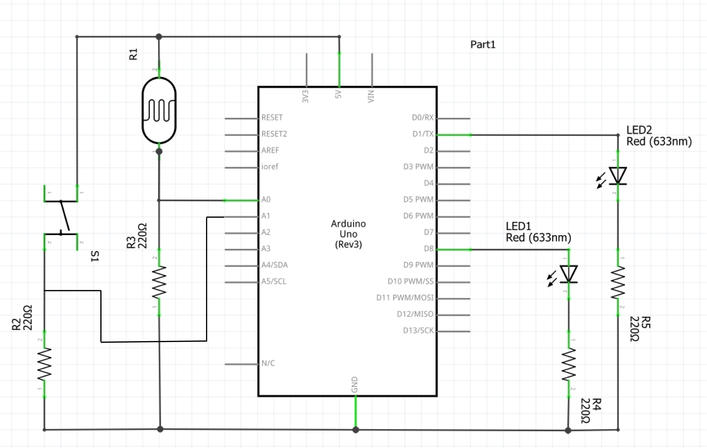
Schematic:
Arduino code snippet:
if (photoState >= 20 && photoState <= 150) {
  flickerLight(currentLed);  //flickerLight(yellowPin)
  digitalWrite(currentLed == yellowPin ? bluePin : yellowPin, LOW);
  // 1) currentLed == yellowPin => checks if value is yellowPin
  // 2) ? bluePin : yellowPin => if 1st condition == true, turn off bluePin, otherwise turn off yellowPin
} else if (photoState <= 10) {
  digitalWrite(currentLed, LOW);
  flickerDark(currentLed == yellowPin ? bluePin : yellowPin);
}

if (buttonState == HIGH) {  // if button is pressed, toggles value of "currentLed" between 'yellowPin' & 'bluePin'
  currentLed = (currentLed == yellowPin) ? bluePin : yellowPin;
  delay(200);
}
I had the hardest time implementing this change: button applies blinking patterns to different LEDs. And through very extensive research I learned about the conditional (ternary) operator. I realised after hours of experimenting and researching that I needed to create a variable to keep track of the LED state: “currentLed”. By incorporating this with the conditional (ternary) operator, I was able to create a mechanism where if the button was pressed, flickerLight/ flickerDark would correspondingly be applied to the opposite LED pin. Whilst it was definitely a pain in the sense that I struggled with this specific implementation for hours, I was very pleased with the end result. With regards to future improvements/ projects, I’d like to create a moodlight. I could use the tricolour LED, switch and trimpot. The trimpot could control the colour displayed and the switch, likewise to this assignment, could afftect the flicker pattern displayed.