
concept:
For this assignment, I decided to make a simple circuit using three LEDS, a switch and a potentiometer.
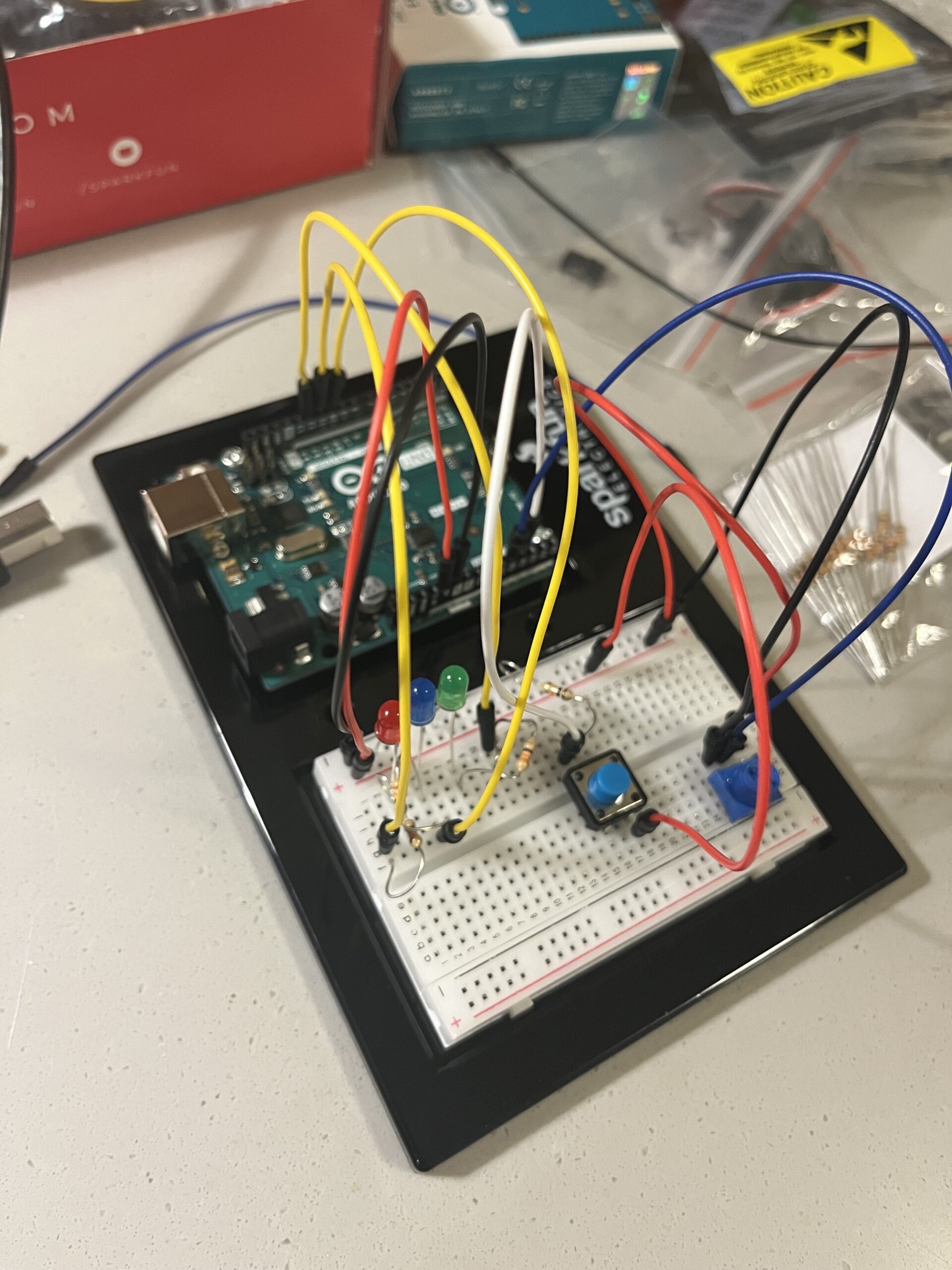
 The idea is that it functions as a way to communicate three moods: anger, sadness and happiness. The mood is decided through the potentiometer, which maps the analog reading to a number within the range 0 – 90. If it’s in between 0-30, the green LED lights up, if it’s between 30 – 60, the blue LED lights up, and anything after 60 up till 90 makes the red LED light up. The LEDs blink in morse code – the red LED spells ANGRY, the blue LED spells SAD, and the green LED spells HAPPY. The digital switch in the circuit is used to turn the circuit on or off, with the LEDs only blinking if the switch is pressed.
code highlights:
const int greenLED = 12;
const int redLED = 11;
const int blueLED = 10;
const int btn = A2;
const int pot = A1;
int value;
int currLED = 0;

void flashDot() {
  digitalWrite(currLED, HIGH);
  delay(250);
  digitalWrite(currLED, LOW);
  delay(250);
}

void flashDash() {
  digitalWrite(currLED, HIGH);
  delay(1000);
  digitalWrite(currLED, LOW);
  delay(250);
}

void setup() {
  pinMode(redLED, OUTPUT);
  pinMode(greenLED, OUTPUT);
  pinMode(blueLED, OUTPUT);
  Serial.begin(9600);
}

void loop() {
  int btnState = digitalRead(btn);
  int potVal = analogRead(pot);
  value = map(potVal, 0, 1023, 0, 90);

  Serial.println(currLED);
  Serial.println(value);
  if (btnState == LOW) {
    digitalWrite(greenLED, LOW);
    digitalWrite(redLED, LOW);
    digitalWrite(blueLED, LOW);
    // currLED = 0;
  }
  if (value <= 30) {
    currLED = greenLED;
    //     digitalWrite(redLED, LOW);
    // digitalWrite(blueLED, LOW);
  } else if (value > 30 && value <= 60) {
    currLED = blueLED;
    //     digitalWrite(greenLED, LOW);
    // digitalWrite(redLED, LOW);
  } else {
    currLED = redLED;
    //         digitalWrite(greenLED, LOW);
    // digitalWrite(blueLED, LOW);
  }

  if (btnState == HIGH) {
    //   digitalWrite(greenLED, LOW);
    //   digitalWrite(redLED, LOW);
    //   digitalWrite(blueLED, LOW);
    // } else if (btnState == LOW) {
    if (currLED == greenLED) {
      digitalWrite(blueLED, LOW);
      digitalWrite(redLED, LOW);
      flashDot();  // H
      flashDot();
      flashDot();
      flashDot();
      delay(1000);  // Gap between letters

      flashDot();  // A
      flashDash();
      delay(1000);  // Gap between letters

      flashDot();  // P
      flashDash();
      flashDot();
      flashDot();
      delay(1000);  // Gap between letters

      flashDot();  // P
      flashDash();
      flashDot();
      flashDot();
      delay(1000);  // Gap between letters

      flashDash();  // Y
      flashDot();
      flashDash();
      flashDash();
      delay(1000);  // Gap between words
    } else if (currLED == blueLED) {
      digitalWrite(greenLED, LOW);
      digitalWrite(redLED, LOW);
      flashDot();  // S
      flashDot();
      flashDot();
      delay(1000);  // Gap between letters

      flashDot();  // A
      flashDash();
      delay(1000);  // Gap between letters

      flashDash();  // D
      flashDot();
      flashDot();
      delay(1000);  // Gap between words
    } else if (currLED == redLED) {
      digitalWrite(blueLED, LOW);
      digitalWrite(greenLED, LOW);
      flashDot();  // A
      flashDash();
      delay(1000);  // Gap between letters

      flashDash();  // N
      flashDot();
      delay(1000);  // Gap between letters

      flashDash();  // G
      flashDot();
      flashDot();
      delay(1000);  // Gap between letters

      flashDot();  // R
      flashDash();
      flashDot();
      delay(1000);  // Gap between letters

      flashDash();  // Y
      flashDash();
      delay(1000);  // Gap between words
    }
  }
}
The code is pretty simple and straightforward. One thing I like about my code is using the functions flashDash and flashDot, as it made it much easier to translate the morse code into blinking.
reflections:
One thing I struggled with and couldn’t really fix and/or understand why it was happening was the delayed transition between states, i.e. it takes a while to go from green to red etc., or even to turn off (as seen in the video). In the future, I’d want to be able to assess the root cause of this issue as it could be very problematic in other sorts of circuits where timing is very necessary.