
Concept
In the fascinating world of Arduino projects, creativity knows no bounds. One project that particularly caught my attention was the creation of a sound sensor-controlled LED using the Arduino UNO. To embark on this journey, I realized that I needed a sound sensor, which wasn’t included in the kit I was provided. My curiosity got the best of me, and I ordered the module to explore how it would all come together. The end result was a captivating LED that reacted to sound, and today, I’ll guide you through how I crafted my own sound sensor-controlled LED using an Arduino UNO.
 Calibrating of Sound Sensor
Before diving into the assignment, it’s essential to calibrate the sound sensor for accurate results. The sound sensor module comes equipped with a potentiometer, and I followed these calibration steps:
- I adjusted the potentiometer until I reached the desired threshold value.
- I stood in front of the sensor and clapped my hands.
- After continuous adjustments to the potentiometer, I observed the LED blinking.
Required Hardware
- Arduino UNO
- Sound sensor module
- LED
- Resistor (330 ohms)
- Jumper wires
- Breadboard
- USB cable
- Computer with Arduino IDE installed
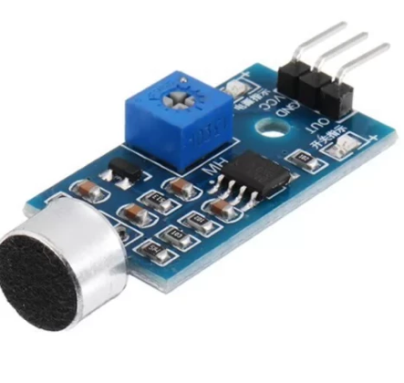
Sound Sensor Module
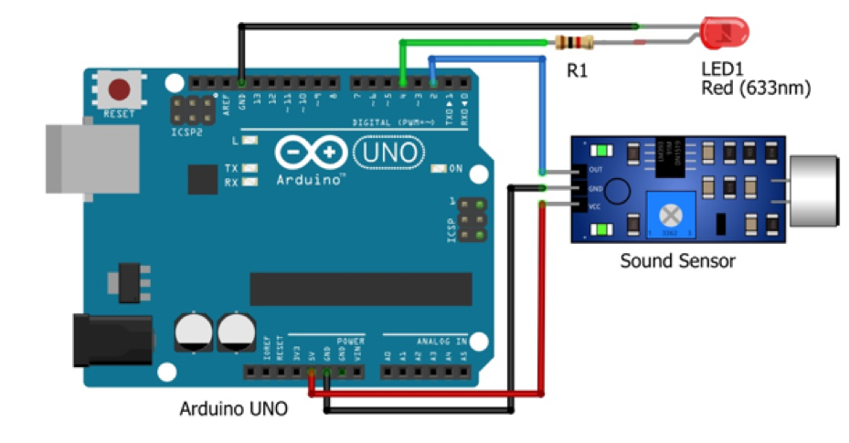
Circuit Diagram
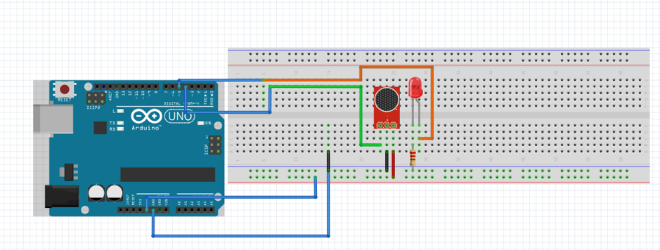
The circuit diagram was created using Fritzing and includes the sound sensor, LED, resistor, Arduino UNO, and breadboard.
const int soundSensorPin = 5; // Sound sensor connected to digital pin 5
const int ledPin = 4;         // LED connected to digital pin 4

void setup() {
  pinMode(soundSensorPin, INPUT);
  pinMode(ledPin, OUTPUT);
}

void loop() {
  // Read the sound sensor input
  int soundValue = digitalRead(soundSensorPin);

  if (soundValue == HIGH) {
    // If sound is detected, turn on the LED
    digitalWrite(ledPin, HIGH);
  } else {
    // No sound detected, turn off the LED
    digitalWrite(ledPin, LOW);
  }
}
By following these steps, the code effectively monitors the sound for claps or any sound after detection, and the Arduino sends the signal of ‘High’ to the LED.
Connecting the Components
I connected the sound sensor to the Arduino UNO as follows:
- VCC of the sound sensor to 5V on the Arduino.
- GND of the sound sensor to GND on the Arduino.
- D0 of the sound sensor to digital pin 5 on the Arduino.
Connect the LED to the Arduino
I connected the longer leg (anode) of the LED to digital pin 4 on the Arduino.
I connected the shorter leg (cathode) of the LED to a 330-ohm resistor.
I connected the other end of the resistor to the GND on the Arduino.
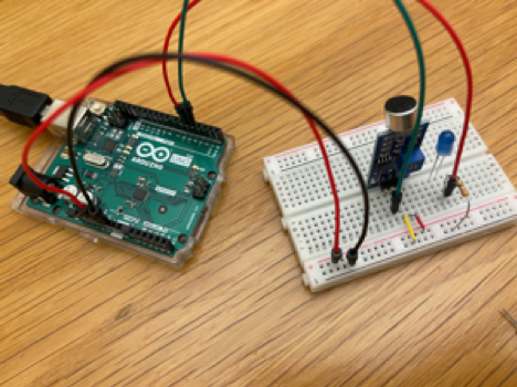
Hardware Implementation
Video Illustration
Working Explanation, Testing, Fine-Tuning, and Conclusion:
My quest to build an LED controlled by a sound sensor began with designing the circuit and coding it using the Arduino program. I eagerly tested the system by making noises close to the sensor after uploading the code, which caused the captivating LED response. As I fine-tuned the ‘threshold’ value, I found the sweet spot of sensitivity, ensuring the sensor responded with precision. In short, this assignment not only revealed the art of sensor interaction but also brought sound and light together in perfect harmony. With the Arduino UNO as my conductor, I transformed a simple kit into an extraordinary, hands-free LED display, illustrating the limitless possibilities of the Arduino world.