Final Project

For my final project, I first decided to utilize NeoMatrix to create an interactive pixel art board. In the beginning everything was going okay, I spent a few nights trying to connect the wires to the tiny holes in the NeoMatrix and in the end connect two out of four boards, mainly because two other boards failed to light up. The soldering process was probably the hardest part of the entire project. Since I was not used to the machine and had barely any experience beforehand, I was left in quite a tough situation, with a bunch of burn marks and a hope which was ultimately extinguished after failing to connect a 16×16 board.

Although the situation was hard, I finished my code for the p5js end. A snipped of the most important bits can be seen below.

const WINDOW_WIDTH = 800
const WINDOW_HEIGHT = 400
const TILE_WIDTH = WINDOW_WIDTH/2
const TILE_HEIGHT = WINDOW_HEIGHT
const NUMBER_ROWS = 8
const NUMBER_COLUMNS = 8
const WIDTH = TILE_WIDTH/NUMBER_COLUMNS
const HEIGHT = TILE_HEIGHT/NUMBER_ROWS

let serial;

let pressed_id = 0;
let state = 0;
let r = 255;  
let g = 255;
let b = 255;
boxes = []

class Box{
  constructor(x, y, w, h, id){
    this.x_pos = x
    this.y_pos = y
    this.box_width = w
    this.box_height = h
    this.id = id
    this.clicked_state = 0
  }
  
  display(){
    if(this.clicked_state == 1){
      fill(255, 0, 0)
    }
    else{
      fill(255, 255, 255)
    }
    rect(this.x_pos, this.y_pos, this.box_width, this.box_height)
  }
}

function setup() {
  
  createCanvas(WINDOW_WIDTH, WINDOW_HEIGHT);
  background(220);
  
  id = 0
  for(let n = 0; n < 3; n++){
    for(let i = 0; i < NUMBER_ROWS; i++){
      box_rows = []
      for(let j = 0; j < NUMBER_COLUMNS; j++){
        append(box_rows, new Box(n*TILE_WIDTH+j*WIDTH, i*HEIGHT, WIDTH, HEIGHT, id))
        id++
        
      }
    append(boxes, box_rows)
    }
  }
}

function draw() {
  for(let i = 0; i < boxes.length; i++){
    for(let j = 0; j < NUMBER_COLUMNS; j++){
      boxes[i][j].display()
    }
  }
}

function mouseClicked(){
  for(let i = 0; i < boxes.length; i++){
    for(let j = 0; j < NUMBER_COLUMNS; j++){
      if(mouseX > boxes[i][j].x_pos && mouseX < boxes[i][j].x_pos+boxes[i][j].box_width &&
         mouseY > boxes[i][j].y_pos && mouseY < boxes[i][j].y_pos+boxes[i][j].box_width){
        // console.log("(" + boxes[i][j].x_pos + ", " + boxes[i][j].y_pos + ", " +boxes[i][j].id +")")
        
        if(boxes[i][j].clicked_state == 0){
          boxes[i][j].clicked_state = 1
        }
        else{
          boxes[i][j].clicked_state = 0
        }
        state = boxes[i][j].clicked_state
        pressed_id = boxes[i][j].id 
      }
    }
  }
}

function keyPressed(){
  if (key == " ") {
    // important to have in order to start the serial connection!!
    setUpSerial();
  }
}

// This function will be called by the web-serial library
// with each new *line* of data. The serial library reads
// the data until the newline and then gives it to us through
// this callback function
function readSerial(data) {
  ////////////////////////////////////
  //READ FROM ARDUINO HERE
  ////////////////////////////////////

  if (data != null) {
    // make sure there is actually a message
    // split the message
    let fromArduino = split(trim(data), ",");
    // if the right length, then proceed
    if (fromArduino.length == 1) {
      // only store values here
      // do everything with those values in the main draw loop
      
      // We take the string we get from Arduino and explicitly
      // convert it to a number by using int()
      // e.g. "103" becomes 103
      rVal = int(fromArduino[0]);
      // alpha = int(fromArduino[1]);
    }

    //////////////////////////////////
    //SEND TO ARDUINO HERE (handshake)
    //////////////////////////////////
    let sendToArduino = pressed_id + "," + state + "," + g + "," + r + "," + b  + "\n";
    console.log(pressed_id + "," + state + "," + g + "," + r + "," + b  + "\n")
    writeSerial(sendToArduino);
  }
}

The code ran perfectly when it came to execution. The tiles were matched with the pixel placement of the NeoMatrix, which went in a zigzag pattern. After reading many pages of documentation for the Adafruit electronics, I was able to properly display the selected pixel from the p5js screen. Although all seem dandy, disaster struck at 12am in the morning.

The serial connection was working properly and the Adafruit library was maintaining the pixel array. However, unbeknownst to me, who was testing the board with only one color, green, the board did not display colors properly. After realizing this fact, I set out to work and spent a good couple of hours trying to fix the issue. After reviewing the documentation for what felt like the hundredth time, the board was still not working. Within the NeoMatrix setup, there was a line called “NEO_GRB” which stands for Green Red Blue. Without the serial connection, this line would produce normal colors that were set on a pixel. However, when paired, the matrix would produce only green,  blue and turquoise. When changed to “NEO_RGB”, the pixel would be colored either red, blue or purple. No matter which way I tried, only two out of three colors would show up. By checking on similar issues online, I found that many people were met with the same issue, but little knew of how to help. I tried many possible solutions but none of them worked. With only 2 days left until the showcase and the deadline had already passed, I was forced to abruptly change my final project. I decided to recreate an Etch-A-Sketch.

I admit that it was my issue that I did not start the serial connection process sooner, but having finished both the code and physical part, I believed there to be no issue with the process. Unfortunately, some things are just bound to fail and to save myself tears I decided to not waste time on something that I would not be able to fix. At least, if I tried something else, I would have somewhat of a satisfactory product by the end. Although my original idea is something I am very much more proud of, I believe that navigating through this crisis taught me to think of every detail that could go wrong in the future.

The Etch-A-Sketch was a project I believed to be very easily doable, even within the few days I had left. I already had code prepared for this project as it was also one of my original ideas at the start. All that was left was to create the physical components. By using potentiometers and a flex sensor, I would attempt to recreate a cult classic. The flex sensor would be used to detect rapid movement of an external device and delete the screen, imitating the shaking needed to erase an Etch-A-Sketch drawing.

For the Arduino, the code was very simple. I only needed to collect the analog reads and calculate the angle of flex that would be used to clear the screen. The Arduino code can be seen below. The basic premise of the code is to gather the inputs from the flex sensor and the two potentiometers and send them to p5js for use. The LED code was used as control to check whether there was serial connection happening between Arduino and p5js.

// Measure the voltage at 5V and the actual resistance of your
// 47k resistor, and enter them below:
const float VCC = 4.98; // Measured voltage of Arduino 5V line
const float R_DIV = 47500.0;

// Upload the code, then try to adjust these values to more
// accurately calculate bend degree.
const float STRAIGHT_RESISTANCE = 37300.0; // resistance when straight
const float BEND_RESISTANCE = 90000.0; // resistance at 90 deg

int leftLedPin = 2;
int rightLedPin = 5;

void setup() {
  // Start serial communication so we can send data
  // over the USB connection to our p5js sketch
  Serial.begin(9600);

  // We'll use the builtin LED as a status output.
  // We can't use the serial monitor since the serial connection is
  // used to communicate to p5js and only one application on the computer
  // can use a serial port at once.
  pinMode(LED_BUILTIN, OUTPUT);

  // Outputs on these pins
  pinMode(leftLedPin, OUTPUT);
  pinMode(rightLedPin, OUTPUT);

  // Blink them so we can check the wiring
  digitalWrite(leftLedPin, HIGH);
  digitalWrite(rightLedPin, HIGH);
  delay(200);
  digitalWrite(leftLedPin, LOW);
  digitalWrite(rightLedPin, LOW);

  // start the handshake
  while (Serial.available() <= 0) {
    digitalWrite(LED_BUILTIN, HIGH); // on/blink while waiting for serial data
    Serial.println("0,0,0"); // send a starting message
    delay(300);            // wait 1/3 second
    digitalWrite(LED_BUILTIN, LOW);
    delay(50);
  }
}

void loop() {
  // wait for data from p5 before doing something
  while (Serial.available()) {
    digitalWrite(LED_BUILTIN, HIGH); // led on while receiving data

    int left = Serial.parseInt();
    int right = Serial.parseInt();
    if (Serial.read() == '\n') {
      digitalWrite(leftLedPin, left);
      digitalWrite(rightLedPin, right);

      int shaker = analogRead(A0);
      float flexV = shaker * VCC / 1023.0;
      float flexR = R_DIV * (VCC / flexV - 1.0);

      float angle = map(flexR, STRAIGHT_RESISTANCE, BEND_RESISTANCE,
                   0, 90.0);

      int sensor = analogRead(A2);
      delay(5);
      int sensor2 = analogRead(A5);

      Serial.print(angle);
      Serial.print(',');
      Serial.print(sensor);
      Serial.print(',');
      Serial.println(sensor2);
    }
  }
  digitalWrite(LED_BUILTIN, LOW);
}

To emulate the screen of a Etch-A-Sketch, p5js was utilized with a class that would serve as the tip of the drawing needle. The code, which can be seen below, received sensor data from Arduino in order to move the elements on screen as well as delete them.

class Ball{
  constructor(x_pos, y_pos, radius, color){
    this.x = x_pos
    this.y = y_pos
    this.r = radius
    this.c = color
    this.weight = 2
    this.x_prev = x_pos
    this.y_prev = y_pos
  }
  
  moveX(value){

    this.x = value; 
    
    
  }
  
  moveY(value){
    this.y = value;
  }
  
  display(){
    stroke(this.c)
    
    if(this.x_prev == 0 && this.y_prev == 0 ||
        this.x_prev == this.r && this.y_prev == this.r){
      strokeWeight(0)
    }
    else{
      strokeWeight(this.weight)
    }
    line(this.x_prev, this.y_prev, this.x, this.y)
    this.x_prev = this.x
    this.y_prev = this.y
  }
  
  changeCol(col){
    this.c = col;
  }
  
  changeWeight(weight_){
    this.weight = weight_
  }
}

let shaker = 0;
let rVal = 0;
let alpha = 0;
let left = 0;
let right = 0;

let canvas;
let current_theme = 255;
let button_state = 0;

let colorPicker;
let button;
let slider;

function setup() {
  canvas = createCanvas(600, 600);
  textSize(18);
  background(255)
  
  colorPicker = createColorPicker('#ed225d');
  colorPicker.position(width+5, 0);
  colorPicker.size(50,200)
  
  button = createButton("Switch Theme");
  button.position(width+5, 205)
  button.size(50,50)
  button.mousePressed(switchTheme)
  button.style('font-size', '10px')
  
  slider = createSlider(0, 10, 0, 1);
  slider.position(width-35, 320);
  slider.style("transform","rotate(90deg)");
  
  button2 = createButton("Save Drawing");
  button2.position(width+5, 400)
  button2.size(50,50)
  button2.mousePressed(saveDrawing)
  button2.style('font-size', '10px')

  mover = new Ball(rVal, alpha, 2, "#000")
  
  clearScreen();
}

function draw() {
  let val1 = map(rVal, 0, 1023, mover.r, width-mover.r)
  let val2 = map(alpha, 0, 1023, mover.r, height-mover.r)
  
  mover.display();
  mover.moveX(val1);
  mover.moveY(val2);
  
  mover.changeCol(colorPicker.color())
  
  clearScreen();
  
  mover.changeWeight(slider.value()+2)
  // one value from Arduino controls the background's red color
  //background(map(rVal, 0, 1023, 0, 255), 255, 255);

  // the other value controls the text's transparency value
  //fill(255, 0, 255, map(alpha, 0, 1023, 0, 255));

//   if (!serialActive) {
//     text("Press Space Bar to select Serial Port", 20, 30);
//   } else {
//     text("Connected", 20, 30);
    

//     // Print the current values
//     text('rVal = ' + str(rVal), 20, 50);
//     text('alpha = ' + str(alpha), 20, 70);

//   }
  // let writer = createWriter('newFile.txt');
  // writer.write([rVal, alpha]);
  // writer.close()
}

function keyPressed() {
  if (key == " ") {
    // important to have in order to start the serial connection!!
    setUpSerial();
  }
}

function clearScreen(){
  if(shaker > 200){
    background(current_theme)
  }
}

function switchTheme(){
  button_state++;
  if(button_state >= 2){
    button_state = 0
  }
  if(button_state == 0){
    background(255)
    current_theme = 255
  }
  else{
    background(0)
    current_theme = 0
  }
}

function saveDrawing(){
  save(canvas, "myCanvas", 'png');
}


function readSerial(data) {
  ////////////////////////////////////
  //READ FROM ARDUINO HERE
  ////////////////////////////////////

  if (data != null) {
    // make sure there is actually a message
    // split the message
    let fromArduino = split(trim(data), ",");
    // if the right length, then proceed
    if (fromArduino.length == 3) {
      // only store values here
      // do everything with those values in the main draw loop
      
      // We take the string we get from Arduino and explicitly
      // convert it to a number by using int()
      // e.g. "103" becomes 103
      shaker = int(fromArduino[0]);
      rVal = int(fromArduino[1]);
      alpha = int(fromArduino[2]);
    }

    //////////////////////////////////
    //SEND TO ARDUINO HERE (handshake)
    //////////////////////////////////
    let sendToArduino = left + "," + right + "\n";
    writeSerial(sendToArduino);
  }
}

Although the code is quite simple, due to the time constraint posed on me after the initial project failed, there was little to be done to increase the complexity of it. To give the users some degree of freedom, I added a color picker, a stroke changer and buttons to change the theme as well as save the canvas drawing, if they wish to do so. The screen is deleted upon shaking the shaker that comes with the Arduino.
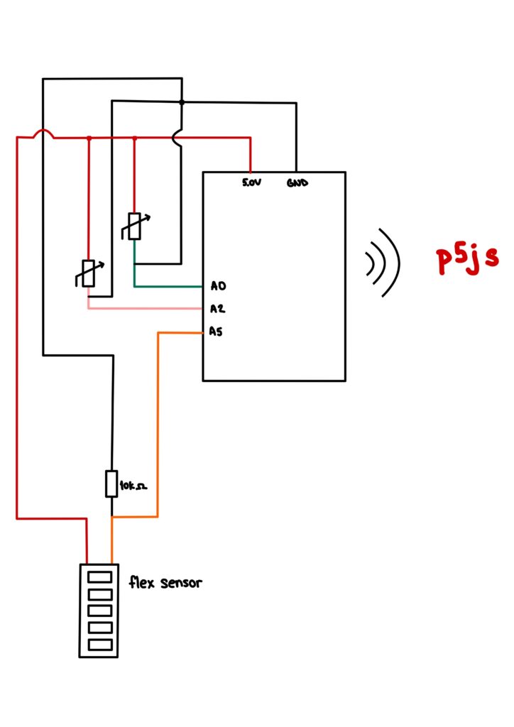
Arduino and Circuit sketch

Reflection

This project was quite fun to work on. Although my initial idea failed, I am happy to have produced at least something to show my passion for Interactive Media. I would love to rework my initial project and attempt to make it work after I have finished with this class. Knowing what went wrong and how I could have fixed it with a saner state of mind might just be what pushed me to pursue Interactive Media and Physical Computing in the long run. For now, I am just grateful to have a physical product with me to show at the Showcase and even though I wish I could have done more, I realized it is sometimes important to start anew in order to learn more than I would have if I had continued to be stuck on the broken project. I loved taking Introduction to Interactive Media this semester and I hope that by continuing my Interactive Media Minor journey, I will be able to learn much more about both coding and the physical components that bring our code to life.

Final Project – The Boy Who Fell

I am excited to present to you all the final video game I made for this class utilizing p5 js and Arduino which is called The Boy Who Fell:

The Boy Who Fell is a survival game where you must control a boy and keep him above by utilizing the platforms from floating in below. But be careful as some of the platforms are spikes which will decrease the number of lives, but you can replenish those by jumping onto the wooden platforms. Also be wary of the row of spikes on the top so don’t stick onto one platform for too long!

User Testing

Sanjana helped me in the user testing. She was able to figure out how to play the game using just the on-screen instructions. What she did needed help in explaining was the lives system and how it worked which was the spikes take away life points while wood restores them until a maximum of 10. I decided to make wood give life for balancing sake.

Implementation

I started out in p5 js by creating the game with different classes such as Game, Player, and Platforms. The p5 js handles different functions such as the gravity of the player, randomizing which platform will appear and the overall design of the game.

For the Arduino, I added buttons onto the solderless board as to emulate the feeling of holding a controller. The controller is used in order to move the boy left or right. I set it so pressing a specific button sends either 1 or 2, depending on the button, to p5 js through which it detects which input is being pushed the and the boy moves in that direction.

In the end, only the Arduino is sending data to p5 js which is the value of what button is being pressed which is then stored in a variable and then compared to in an IF statement in order to determine which direction the boy moves.

I’m particularly proud of how I implemented the different platforms and they come from the bottom and the interaction between the player and the platform. I had even more platforms ready with different interactions but it proved to be too difficult and too much according to some feedback, so I eased the game down.

For improvements, I can improve the controller used in order to play the game but making a controller out of boxes and using bigger and better buttons. The game graphics can be improved as well as the instructions describing the game.

User Testing

User Testing:

To conduct user testing, I had Moeez and Sanjana play my game in its initial state, and they provided me with valuable feedback, which I incorporated into my project. Initially, my game required the user to wait for the flower to reach the bottom of the screen and overlap with the corresponding flower image at the bottom. Sanjana suggested changing the game concept to flower catching and increasing the speed, which I agreed to as it adds excitement. I also initially made my game with a fixed speed throughout but Moeez recommended starting with a slower speed and gradually increasing it to allow users to get accustomed to it. To further enhance the user experience, I plan to add on-screen messages, such as “wrong flower pressed” and “good job!” to make the game more interactive.

Video:

https://youtube.com/shorts/7kJ7MyrLNME


Final Project

Final Project – juicy jackpot

Concept:

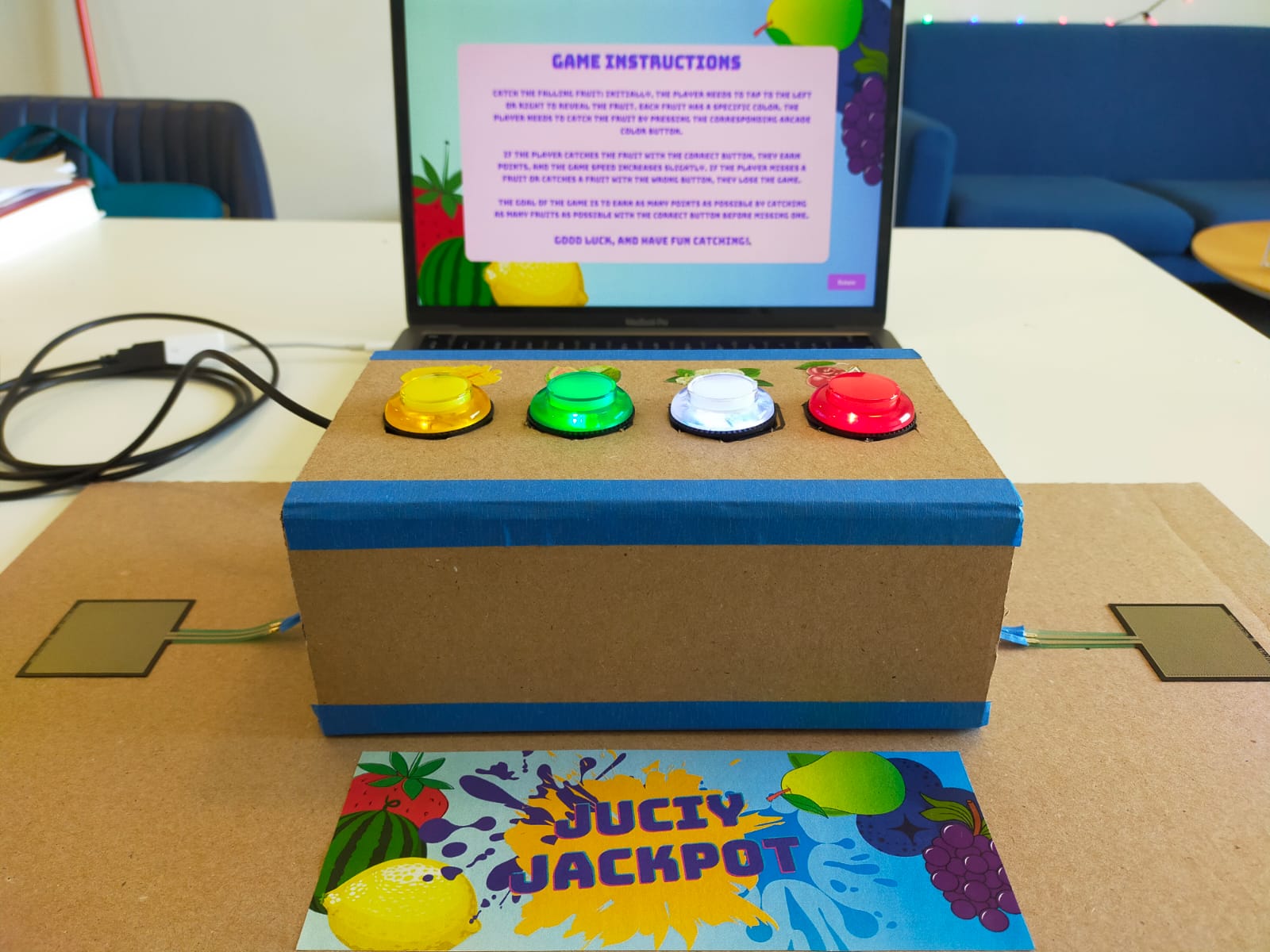
The game I have designed is an engaging and interactive experience, incorporating elements from classic games such as piano tiles, paddle catch, and reaction time games. The central theme of the game is simple yet delightful – players are tasked with discovering hidden fruit and must catch the correct fruit to earn points and progress through the levels. As the game proceeds, the speed of play increases, demanding rapid reflexes and quick decision-making from players to succeed. To uncover the hidden fruit, players must stay alert and swiftly respond to left or right signs, then press the correct arcade button to capture the fruit they seek. The game promises a thrilling and immersive experience, testing players’ skills and keeping them captivated as they strive to achieve the highest score possible.

Implementation:

Building and executing the entire setup for my project was a challenging task, but I am thrilled with the results. I decided to use two force sensors to track left and right movements and four arcade buttons to represent the different fruits. These force sensors typically provide values ranging from 0 to 1023, and while I initially mapped them using Arduino code, it became complicated to send so many values over serial communication. So, I resorted to mapping the values in p5js, which proved to be a more effective solution.

Using this setup, I was able to receive values from both force sensors and the arcade buttons over serial communication. While soldering the force sensors, I encountered some issues with the values changing, but I was able to remap them successfully. If the value is above 100 for one sensor, it’s pressed, and for the other, it’s above 500.

To make the game more engaging, I randomly assigned the fruits and direction arrows. Initially, I had planned to implement a piano tiles-style game with increased complexity, but that wouldn’t allow users to play completely. So, I opted for a randomly falling catch game instead. I first tested the collision and mapping of objects with keyboard keys and then proceeded with mapping them with the Arduino reading.

During testing, I faced a lagging issue while storing all mapped values in an array after splitting the string from the Arduino. However, I was able to resolve this issue by using separate variables, simple if-else statements, and increasing the frame rate.

Mapping the values for the force sensors and arcade buttons to their respective fruits and direction arrows was a crucial step, and I am particularly proud of how well it turned out. Overall, I am pleased with the final result and excited to continue improving the game in the future.

p5js code:

link: https://editor.p5js.org/Sanjana-Nambiar/sketches/-JxDz5psg

Arduino code:

//declaring all the port pins as const int
const int yellow = 13;
const int green = 11;
const int blue = 9;
const int red = 7;

const int left = A3;
const int right = A1;

void setup() {
  //serial port activation 
  Serial.begin(9600);

  //declare the switches as digital input devices
  pinMode(yellow, INPUT_PULLUP);
  pinMode(green, INPUT_PULLUP);
  pinMode(blue, INPUT_PULLUP);
  pinMode(red, INPUT_PULLUP);

  pinMode(left, INPUT);
  pinMode(right, INPUT);
}

void loop() {
  String arrow;
  String fruit;
  String message;

//printig the values from the left and right sensors 
  int sensor1 = analogRead(left);
  int sensor2 = analogRead(right);

  Serial.print(sensor1);
  Serial.print(",");
  Serial.print(sensor2);
  Serial.print(",");

//since the arcade buttons are pullup buttons 
//they are high when it isnt pressed.
  if(digitalRead(yellow) == HIGH)
    {Serial.print("0,");}
  else 
    {Serial.print("1,");}

  if(digitalRead(green) == HIGH) 
    {Serial.print("0,");}
  else 
    {Serial.print("1,");}

  if(digitalRead(blue) == HIGH)
    {Serial.print("0,");}
  else 
    {Serial.print("1,");}

  if(digitalRead(red) == HIGH) 
    {Serial.println("0");}
  else 
    {Serial.println("1");}

}
User testing:

During the user testing phase, my game was tested by Saamia and Moeez, who found the game instructions to be simple and straightforward. However, they encountered a minor issue when distinguishing between the fruit colors. The confusion arose from the white berry and guava fruits, which shared a similar color scheme. To address this issue, I took the feedback on the board and included pictures of the fruits at the front of the box. This small change resolved the confusion, and the testers were able to play the game smoothly. Overall, the user testing phase yielded positive results, and the feedback provided by Saamia and Moeez allowed me to make an improvement to the game that enhanced the user experience.

Future improvements and reflections:

Looking toward the future, there are several areas where this game could be improved to make it even more engaging and exciting for players. One possibility is to add more layers of complexity to the game. For example, rather than just catching the fruit, players could be required to perform additional tasks before the fruit is revealed. This could include completing a pattern or sequence of movements or even solving simple puzzles. Additionally, the game could be made into a two-player mode, where players compete against each other to catch the most fruit or avoid the most obstacles. This could be accomplished by adding a second set of sensors and buttons or even incorporating motion-tracking technology to track players’ movements in real-time.

Overall, I am very proud of the mapping part of the game, where the sensors and buttons were effectively mapped to the fruits and arrows for catching them. With further development, this game has the potential to become a popular and entertaining addition to the world of physical gaming.


Final User Testing Update

Group: Majid, Hassan, Aaron

Concept

This project aims to create a small-scale self-driving experience. It implements a machine-learning module that captures user hand gestures for steering and a foot pedal for accelerating, braking, and stopping.  A user controls the car by imitating the driving steering wheel movements in real life in front of a computer camera and engaging the pedals with the foot. However, that isn’t implemented yet.

Implementation

To make this possible and achieve a near-real-life driving experience, we implemented a machine learning module that uses a camera to capture a user’s hand gestures. This machine learning module is implemented in p5.js and is synced with the pedal and the robot via Bluetooth; however, that isn’t implemented yet. Regardless, a network is created between the robot and the pedals for user control.

From interacting with the code for the DC motors, it seems the maximum attainable speed is 500, which is relatively slow. However, we implemented a code that prevents the robotic car from crashing. When a user accelerates towards an obstacle, the robot stops, scans 180 deg away from the obstacle, and then moves back. In some cases, it scans and moves toward a direction devoid of obstacles.

We also installed an ultrasonic sensor to help avoid obstacles. The distance sensor is fastened to a servo motor to enable free rotation. This was particularly important because we implemented an algorithm that scans surrounding areas for obstacles and moves the robotic car in a direction that is devoid of obstacles.

Displayed here is the code defining the DC motors and other dependencies.

#include <Servo.h>
#include <AFMotor.h>
#define Echo A0
#define Trig A1
#define motor 10
#define Speed 500 //DC motor Speed
#define spoint 103

Displayed here is the code obstacle avoiding code

void Obstacle() {
  distance = ultrasonic();
  if (distance <= 12) {
    Stop();
    backward();
    delay(100);
    Stop();
    L = leftsee();
    servo.write(spoint);
    delay(800);
    R = rightsee();
    servo.write(spoint);
    if (L < R) {
      right();
      delay(500);
      Stop();
      delay(200);
    } else if (L > R) {
      left();
      delay(500);
      Stop();
      delay(200);
    }
  } else {
    forward();
  }
}

Aspects of the Project we’re proud of.

Our proudest achievement so far is the implementation of the machine learning module.

Also, the algorithm that checks for obstacles in a smart way and prevents users from crashing is a feat we’re most proud of. We believe this is implementation in real life could save lives by preventing vehicular accidents.

Aspects we can improve on in the future.

The most significant aspect of the project we believe would impact the world if worked on is the obstacle sensor that prevents the car from crashing. We believe if this is worked on on a larger scale, it could be implemented in cars to help reduce road accidents.

Regardless, we also believe we can  engineer a reverse the obstacle-sensing algorithm to create an algorithm that could detect cliffs and pot-holes, and dangerous empty spaces on roads to ultimately reduce road accidents.

User Testing

Final Project Documentation – Paxon Premium

Team Members

Zunair, Ishmal, and Abraiz

Concept

Pac-Xon Premium, extended from Pac-Xon Deluxe – a Pac Man inspired game, was one our team member’s childhood favorite. Pac-Xon Deluxe, the original game, is fairly simple with numerous levels with increasing difficulty. The experience of the game seems to be fairly decent and easy at first, however as you start completing the levels it gets interesting. However, the increase in difficulty is very gradual, such that you may lose interest in playing further due to repetitiveness, and even the most difficult level may not present that great of a challenge to you. Additionally, the graphics of the game were classic but old, and we believed we could associate a modern touch and feel to the game and produce a revamped and customized version of it.

The gameplay may seem pretty simple at first glance, so we thought it would be something fairly simple to code. However, as we progressed and laid out the logic and technical aspects that were required for even the smallest of details in the game, we realized that it involves a relatively complex algorithmic approach, rather than using just simple Object Oriented Programming coupled with Javascript Basics. Since we wanted to take the game a step further, we wanted to ensure that almost all objects interact amongst each other, all of which was to be wrapped in the complexity of a tile-based game!

Implementation

Stuff We’re Proud of


Stuff We’re Working On

Final Project – Dance Evolution/User Testing

Concept:

For my final project “Dance Evolution”, I decided to work on a “remake” of a famous Japanese video game called “Dance Revolution.” In this game, instead of being provided the music at the beginning, the user has to press on the tiles in order to generate and construct the music itself track by track. For each round, the user is shown an arrow pointing either to the left or to the right and they have to press on the respective tile in a timely manner, otherwise they lose. Them pressing on the tiles will start slowly “unlocking new tracks,” allowing them to construct the final song.

Implementation:


Arduino:

My Arduino board consisted of 3 force sensors. These would then trigger the work of p5js. However, an issue I faced for some time was that when the sensor was activated, Arduino would register multiple high values of the sensor, which was inconvenient specifically for my project as it would set off a chain of undesirable events. Therefore, when working on my Arduino board and code, I had to make sure I debounced the signal properly so that it only registered the activation only once when the sensor is pressed.

p5.js:

Initially, I thought that the p5.js implementation of the project would be straightforward. However, I encountered a variety of different issues that made me change my approach to making this game. Firstly, I was unable to properly play the sounds of my tracks when the sensors were pressed.  It was very difficult to come up with an algorithm in which the activation of a sensor would lead to the playing of a track in a way that matches the other tracks (that may already be played) rhythmically. Therefore, I decided to play all the tracks in the setup and simply unmute each track when the sensor is triggered.

My p5.js code would take in the values of the sensor, or more specifically “signs” from the Arduino that the sensor was pressed and reached its maximum value, and would use that in order to generate new rounds of the game. My biggest obstacle throughout this process was creating an algorithm that would a) randomly pick between the two different images of arrows, b) make the user go from one round to the other, c) have the pictures be timed so that if the sensor is activated late, the user loses, etc. However, mainly through the usage of the “millis()” function, I was able to tackle these issues.

Code:

p5.js:

let bg;

//variables for all the musical tracks

let bass;

let hat;

let kick;

let snare;

let synth;

let strings;

let vox1;

let vox2;

let now; //variable that trackes the time every time the user presses on a button 

let gameStartTime; //tracks the beginning of each round

let sensorValue;

let middleSensorVal;//value of the sensors that p5js receives from Arduino

let gameState = "start"; // Can be 'start', 'playing', 'end'

let threshold = 5000; //the value for the first arrow that appears

let num = 0; //the value that activates the different cases

let arrowImage = []; //an array that holds the values of the images of the arrows

let randomIndex; //selects a random image from an array 

function preload() {
  vox1 = loadSound("vox_1.mp3");

  kick = loadSound("kick.mp3");

  vox2 = loadSound("vox_2.mp3");

  snare = loadSound("snare.mp3");

  bass = loadSound("hat.mp3");

  strings = loadSound("strings.mp3");

  synth = loadSound("synth.mp3");

  hat = loadSound("hat.mp3");

  bg = loadImage("background_image.png"); 
  
  arrowImage.push(loadImage("rightArrow.png"));
  arrowImage.push(loadImage("leftArrow.png")); //pushing the images into the array 

  bruno = loadFont("BrunoAceSC-Regular.ttf"); //loading the font of the game
}

function setup() {
  createCanvas(windowWidth, windowHeight);
  textAlign(CENTER);
  imageMode(CENTER);

  //playing all the tracks during setup and muting each track

  vox1.setVolume(0);
  vox1.play();
  vox1.loop();

  vox2.play();
  vox2.setVolume(0);
  vox2.loop();

  strings.play();
  strings.setVolume(0);
  strings.loop();

  snare.play();
  snare.setVolume(0);
  snare.loop();

  synth.play();
  synth.setVolume(0);
  synth.loop();

  kick.play();
  kick.setVolume(0);
  kick.loop();

  bass.play();
  bass.setVolume(0);
  bass.loop();

  hat.play();
  hat.setVolume(0);
  hat.loop();
}

function draw() {
  background(220);
  image(bg, width / 2, height / 2, width, height);
  
  //assigning different functions to different states of the game

  if (gameState == "start") {
    drawMainPage();
  } else if (gameState == "instructions") {
    drawInstructions();
  } else if (gameState == "playing") {
    drawGame();
  } else if (gameState == "win") {
    drawWinScreen();
  } else if (gameState == "loss") {
    drawLossScreen();
  } 
}

function windowResized() {
  resizeCanvas(windowWidth, windowHeight);
}

function drawMainPage() {
  textSize(70);
  fill("rgb(255,0,163)");
  stroke(255);
  strokeWeight(5);
  textWrap(WORD);
  textFont(bruno);
  text("Dance Evolution", width / 2, height / 5, width / 13);

  textSize(18);
  fill("white");
  stroke(0);
  strokeWeight(4);
  textFont(bruno);
  text("Press the Space Bar for the Instructions", width / 2, height / 1.2);
}

//setting up the serial connection

function keyPressed() {
  if (key == " ") {
    setUpSerial();
    gameState = "instructions";
  }
}

function drawInstructions() {
  textSize(60);
  fill("rgb(255,0,163)");
  stroke(255);
  strokeWeight(5);
  textWrap(WORD);
  textFont(bruno);
  text("Instructions", width / 2, height / 5);
  
  textWrap(WORD);
  textSize(16);
  stroke(0);
  strokeWeight(3);
  fill(255);
  textFont(bruno);
  text(
    "Once you start the game, you will see an arrow. Wherever the arrow points, that's the tile you should click on. Once you click on the tile, you will hear a track playing. Below the picture of the arrow, you will see the number of seconds you are given for each round. If you don't press the tile in time, you LOSE! If you manage to press on all the arrows on time and play all the tracks, you WIN!",
    0,
    height/2.5,
    width
  );
  
  textSize(18);
  fill("white");
  stroke(0);
  strokeWeight(4);
  textFont(bruno);
  text("Step on the Tile in the Middle to Play!", width / 2, height / 1.2);

  if (middleSensorVal == 1023) {
    gameState = "playing";
    restartRound(); //begins the game when the button is pressed
  }
}

function drawGame() {
  textSize(60);
  fill("rgb(255,0,163)");
  stroke(255);
  strokeWeight(5);
  textWrap(WORD);
  textFont(bruno);
  text("DANCE!", width / 2, height / 6.5);
  
  //tracking to see if the time that passed since the start of the round is less than the time the threshold

  if (millisInGame() < threshold && num < 8) {
    image(arrowImage[randomIndex], width / 2, height / 2, width/2, height/2);

    fill(255);
    strokeWeight(0);
    text(
      round(millisInGame() / 1000) + "/" + round(threshold / 1000) + " s",
      width / 2,
      height / 1.15
    );
  }
  
  //assigning the conditions for loss
  
  if (millisInGame() > threshold && num < 8) {
    gameState = "loss";
  }

  if (sensorValue === 1023 && num < 9) {
    num++;
    console.log(num);
    restartRound();
    threshold = threshold * 0.92;
    console.log(threshold);
    flag = true;
  }

  if (num == 8) {
    drawWinScreen();
  }
  
  switch (num) {
    case 0:
      break;
    case 1:
      vox1.setVolume(0.2);
      break;
    case 2:
      vox2.setVolume(0.2);
      break;
    case 3:
      kick.setVolume(0.2);
      break;
    case 4:
      bass.setVolume(0.2);
      break;
    case 5:
      snare.setVolume(0.2);
      break;
    case 6:
      hat.setVolume(0.2);
      break;
    case 7:
      synth.setVolume(0.2);
      break;
    case 8:
      strings.setVolume(0.2);
      break;
  }
}

function drawWinScreen() {
  background(220);
  image(bg, width / 2, height / 2, width, height);

  textSize(40);
  fill("rgb(255,0,163)");
  stroke(255);
  strokeWeight(5);
  textWrap(WORD);
  textFont(bruno);
  text("CONGRATULATIONS", width / 2, height / 5);
  
  textSize(18);
  fill("white");
  stroke(0);
  strokeWeight(4);
  textFont(bruno);
  text("Step on the tile in the middle to RESTART!", width / 2, height / 1.2);
  
  //restarting the game when the middle sensor is played

  if (middleSensorVal == 1023) {
    gameState = "instructions";
    vox1.setVolume(0);
    vox2.setVolume(0);
    strings.setVolume(0);
    snare.setVolume(0);
    synth.setVolume(0);
    kick.setVolume(0);
    bass.setVolume(0);
    hat.setVolume(0);
    num = 0;
    threshold = 5000;
  }
}

//tracking the start time of each round and generating an index to then randomly generate an image from the array 

function restartRound() {
  now = millis();
  gameStartTime = now;

  randomIndex = floor(random(arrowImage.length));
}

//tracking the difference between the current time and the moment when the game started

function millisInGame() {
  return millis() - gameStartTime;
}

function drawLossScreen() {
  textSize(60);
  fill("rgb(255,0,163)");
  stroke(255);
  strokeWeight(5);
  textWrap(WORD);
  textFont(bruno);
  text("LOSS", width / 2, height / 5);

  if (middleSensorVal == 1023) {
    gameState = "instructions";
    vox1.setVolume(0);
    vox2.setVolume(0);
    strings.setVolume(0);
    snare.setVolume(0);
    synth.setVolume(0);
    kick.setVolume(0);
    bass.setVolume(0);
    hat.setVolume(0);
    num = 0;
    threshold = 5000;
  }
  
  textSize(18);
  fill("white");
  stroke(0);
  strokeWeight(4);
  textFont(bruno);
  text("Step on the tile in the middle to RESTART!", width / 2, height / 1.2);
}

//receiving the information from the Arduino

function readSerial(data) {
  if (data != null) {
    let fromArduino = split(trim(data), ",");

    if (fromArduino.length == 2) {
      
      middleSensorVal = int(fromArduino[0]);
      sensorValue = int(fromArduino[1]);

    }
  }
}

function keyTyped() {
  if (key === 'f') {
    toggleFullscreen();
  }
}
function toggleFullscreen() {
  let fs = fullscreen(); 
  fullscreen(!fs); 
}


Arduino

const int leftPSensor = A0;
const int rightPSensor = A1;
const int middleSensor = A2; 

int lastSensorStateLeft = 0;
int lastSensorStateMiddle = 0;

int threshold = 1022;

bool flag = false;

int rightPressureVal;
int leftPressureVal;
int middleSensorVal;

void setup() {

  pinMode(leftPSensor, INPUT);
  pinMode(rightPSensor, INPUT);
  pinMode(middleSensor, INPUT);
  Serial.begin(4800);
}

void loop() {

  leftPressureVal = analogRead(leftPSensor);
  rightPressureVal = analogRead(rightPSensor);
  middleSensorVal = analogRead(middleSensor);


  if (leftPressureVal < threshold && rightPressureVal < threshold && middleSensorVal < threshold) {
    flag = true;
  } 

  if (flag == true && (leftPressureVal == 1023 || rightPressureVal == 1023)) {
      lastSensorStateLeft = 1023;
      flag = false;
    delay(300);
  } else {
    lastSensorStateLeft = 0;
  }

  if (flag == true && middleSensorVal == 1023) {
      lastSensorStateMiddle = 1023;
      flag = false;
      delay(300);
  } else {
    lastSensorStateMiddle = 0;
  }

  Serial.print(lastSensorStateMiddle);
  Serial.print(", ");
  Serial.println(lastSensorStateLeft);
}

Communication:

The communication between Arduino and p5.js proved to be a difficulty. As mentioned earlier, I tackled the issue of multiple registrations of the activation of the sender by debouncing it and ensuring that the value of the sensor is sent to p5js only once. However, when that was happening, despite p5.js recognizing the value, it would simply ignore it, even though it was clearly instructed to carry out an operation with the value. After some time, I realized that this issue could be resolved by decreasing the baud rate from 9600 to 4800 on both p5js and Arduino, which would allow p5js to recognize the one, small “1023” value that gets lost in a fast stream of values that are being received from Arduino. This was very helpful as it fixed the issue and ensured the smooth operation of the game.

Future improvements:

With this project, I am proud that it ultimately became what I envisioned, albeit with some limitations. I am proud of the algorithm that I used for flipping through rounds using the sensor and playing the different tracks themselves.

In the future I want to make sure there is more randomness to the process in terms of the different tracks that are played because as of now, the tracks are played in the same order. I also want to add different levels of difficulty where the user can choose to make the time given for their step on the tiles shorter. Finally, I want to improve the p5.js – Arduino communication in order to make sure that the user does not have to press on the tiles a few times for the value to be registered, which is an issue I observe currently.

Video:


User Testing:

I conducted user testing on one of my friends, whom I did not have explain the Instructions to. According to him, the instructions were clear. Despite that, he still struggled at times with clicking on the tiles as they would take a few tries for the value to be received by p5.js. All in all, however, he claimed that the game is fairly easy to understand.


Final Project: SHINOBI SPRINT

Introduction & Concept:

I switched from my initial plan of making a simple dino jump game to more colourful and fun game called “SHINOBI SPRINT”. The game is a side-scrolling endless runner game based on the famous ninja from the Naruto anime series, as he runs horizontally and avoids obstacles vertically to score points. The game provides a challenging experience where players need to demonstrate agility and reflexes to achieve high scores.

The main objective of the game is to control Naruto and survive as long as possible while avoiding obstacles coming from right towards Naruto. Players need to control Naruto’s vertical movements to avoid obstacles by moving the ultrasonic distance sensor. The plan initially was to move the hand in front of the sensor but after doing some test runs, I realised that the sensor wasn’t picking the values correctly. So, now the player has to carry the sensor in his/her hand and move it away or towards any surface to the control the vertical movement of Naruto.

The Obstacles in the game appear at regular intervals and move towards Naruto and consist of fire images that are randomly placed on the canvas. Players must navigate Naruto vertically to avoid colliding with the obstacles. Colliding with an obstacle ends the game. The game includes a score system that tracks the player’s survival time. The longer the player survives, the higher the score.

Implementation:

The implementation is again simple, player carries the sensor in his/her hand move it up and down on some surface (preferably table) to make Naruto go up or down. The sensor values start from 0 and for the sake of this project the values only range till 460 to make Naruto go up and down within the canvas.

The goal is to navigate Naruto through the gaps between obstacles and avoid collisions. The game ends when Naruto collides with an obstacle, and the player’s score is displayed.

Arduino:

Using serial communication between p5.JS and arduino, I was able to send distance values to p5.js to control Naruto in the game. The Arduino code is responsible for reading sensor data, processing it, and sending it to the p5.js program. Here’s the Arduino Code:

// defines pins numbers
const int trigPin = 9;
const int echoPin = 10;
// const int ledPin = 3;
// int duty = 10;
// defines variables
long duration;
int distance;
void setup() {
  pinMode(trigPin, OUTPUT); // Sets the trigPin as an Output
  // pinMode(ledPin, OUTPUT); // Sets the trigPin as an Output
  pinMode(echoPin, INPUT); // Sets the echoPin as an Input
  Serial.begin(9600); // Starts the serial communication
}
void loop() {
  // Clears the trigPin
  digitalWrite(trigPin, LOW);
  delayMicroseconds(2);
  // Sets the trigPin on HIGH state for 10 micro seconds
  digitalWrite(trigPin, HIGH);
  delayMicroseconds(10);
  digitalWrite(trigPin, LOW);
  // Reads the echoPin, returns the sound wave travel time in microseconds
  
  duration = pulseIn(echoPin, HIGH);
  // Calculating the distance
  distance = duration * 0.034 / 2;
  // Prints the distance on the Serial Monitor * 0.034 / 2
  // analogWrite(ledPin, duty);
  Serial.println(distance*4);
  delay(150);
}


P5.JS:

The p5.js code handles the game’s main logic and rendering. It includes functions to load images, control the movement of the landscape, manage game states (main screen, gameplay, game over), and handle collisions between objects. The code uses the sprite concept to represent Naruto, obstacles, and other elements in the game. It also includes functions for drawing the main screen and game over screen and the mousePressed function attached to clicking on Play before the start and to restart the game each time it’s over. I’ll be submitting the project below so you can all take a look over the p5.js code.

Communication between Arduino and p5.js

The communication between Arduino and p5.js is established through a serial connection. The p5.js program reads the distance values sent by the Arduino and uses them to control Naruto’s vertical position. The Arduino continuously sends distance data, which is received by the p5.js program. This communication allows the player to control Naruto’s movement in real-time.


Cool Things in the game:

Here are some of game prospects that I am most proud of:

Parallax Landscape: The game features a visually appealing parallax landscape, where the background scrolls at a slower speed than the foreground, creating depth and immersion.

Sprite Animation: The use of sprite animation brings Naruto and other elements to life, enhancing the game’s visual experience.

Intuitive Controls: The game utilizes an Arduino device to control Naruto’s movement, providing a unique and engaging gameplay experience.

Here’s the p5.js code for this project:

Future Improvement

Game Difficulty: Implementing adjustable difficulty levels or introducing new obstacles or power-ups could enhance the game’s replay value.

Audio: Adding sound effects and background music would contribute to the game’s overall atmosphere.

Changing the values received from arduino when communicating data with it: As the sensor values increase from down to up, the movement of Naruto on the screen is opposite the way it should be. I would like to fix this feature in future.


User Testing:

Here’s the video of one of my friends trying to play the game.


I think the controls were not really difficult for the players to understand. My friend was able to figure out the controls on his own and was able to score good score in his 3rd try.

Again, the only problem here is that the movement of Naruto is opposite than the user movement of his/her hands. For example, when going up with the sensor, Naruto goes down. This is one of the main issue I faced and couldn’t find a way to fix it. Hopefully, when I make changes to this project in Future, I’ll be able to figure out the solution for this problem.


Final Project

Project: Petals and Harmony

Concept

My project aims to provide a simple and engaging activity for elderly individuals who may face difficulty attending physiotherapy sessions. The game is nature-themed and involves a flower-catching game set in a forest or garden, accompanied by a calming fairyland-like musical background. This relaxing environment is designed to calm the nerves, similar to a physiotherapy session.

As the game progresses, flowers appear one at a time from a distance and move closer to the player, creating an enjoyable challenge that encourages individuals to exercise their hand-eye coordination and mobility.

Implementation

For my project, I utilized four pressure sensors as analog sensors to capture input from the user’s four fingers. The sensors provided data within a range of 0 to 1023. However, to ensure that a “press” was distinguished from a mere touch, I set a threshold range for the boolean values. If the sensor reading exceeded 500, the boolean value was set to true.

I created four boolean variables, one for each sensor. These variables were set to true when the sensor reading was above 500, and false otherwise. Only when the user pressed the correct pressure sensor, the moving flower appeared and the next flower appeared on the screen.

To create a realistic flower movement effect, I attempted to simulate the appearance of flowers approaching from afar. At first, I considered having the flowers move in four rows, similar to piano tiles. However, I found that manipulating the size and movement angle of the flowers was more effective in achieving the desired effect. With this approach, I was able to create the impression that the flowers were coming closer from a distance.

This is the code that helps me achieve this effect:

angle = radians(126);
image(img,start_x,start_y,size,size);
start_x += speed * cos(angle);
start_y += speed * sin(angle);
size = map(start_y, 466, height, 10, 110);

I calculated the specific angle value to each flower, allowing me to manipulate the x and y coordinates independently. To adjust the size of the flowers, I utilized the map function. Specifically, when the value of the start_y coordinate (the y-coordinate of the flower) was 466, the size of the flower was set to 10. Similarly, when the y-coordinate reached the end of the canvas (i.e., height), the size of the flower was set to 110 using the same ratio.

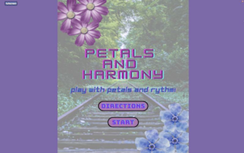
My p5.js project features a main page that showcases the game’s title along with a slogan, as well as two buttons: “Start” and “Instructions.” The instructions section provides a comprehensive guide on how to play the game and includes information on how missed flowers will be displayed at the end of the game. Once the user has gone through the instructions, they can then proceed to start the game.

In the top left corner of the game’s interface, there is a fullscreen button that allows the user to enter or exit fullscreen mode. Since my game is in a vertical orientation, I centered the printing of the game’s background images, while covering the rest of the canvas with a plain colored background.

Arduino Code:

const int pressureSensor0 = A0;
const int pressureSensor1 = A1;
const int pressureSensor2 = A2;
const int pressureSensor3 = A3;
// the setup routine runs once when you press reset:
void setup() {
  // initialize serial communication at 9600 bits per second:
  Serial.begin(9600);
  pinMode(pressureSensor0, INPUT);
  pinMode(pressureSensor1, INPUT);
  pinMode(pressureSensor2, INPUT);
  pinMode(pressureSensor3, INPUT);
}

// the loop routine runs over and over again forever:
void loop() {
  // read the input on analog pin 0:
  int sensorValue0 = analogRead(pressureSensor0);
  int sensorValue1 = analogRead(pressureSensor1);
  int sensorValue2 = analogRead(pressureSensor2);
  int sensorValue3 = analogRead(pressureSensor3);

  // print out the value you read:
  //Serial.print("(");
  Serial.print(sensorValue0);
  Serial.print(", ");
  Serial.print(sensorValue1);
  Serial.print(", ");
  Serial.print(sensorValue2);
  Serial.print(", ");
  Serial.println(sensorValue3);
  //Serial.println(")");

}

P5js Implementation:

Areas I am particularly proud of

I am incredibly proud of creating my first interactive game. In the past, I had made games, but they were never as engaging as this one, which uses a glove to take input from the user. This gave a whole new level of interactivity to the project, making it more engaging and immersive. It reminded me of our in-class discussions, where we talked about the importance of direct input from the user. By using not just visual but touch senses to control the success of the game, I was able to create a unique experience for the player. It was exciting to see my vision come to life and to be able to share it with others. I learned a lot during the process, and I’m looking forward to continuing to explore the possibilities of interactive game development in the future.

Future Improvements

In the future to make the game more engaging and interactive, I am considering adding a multiplayer mode. This would provide an opportunity for players, particularly older individuals, to play with their friends rather than playing alone. I believe that a multiplayer game would instill feelings of healthy competition, making the gameplay even more exciting and encouraging players to keep coming back to the game.

Final Project – Lime Liner

Concept and Implementation: 

For my final project, I created a digital version of the classic Etch-a-Sketch toy which utilizes both Arduino and P5JS. I personalized the design by using neon green and black colors to give it a modern, sleek look. The goal was to replicate the drawing experience of the original toy while adding new features that enhance the user’s creativity and leaving a personal mark on the concept. Additionally, to better reflect my altered version of the toy, I decided to name it Lime Liner.

The Lime Liner was created using an Arduino Uno board and two potentiometers connected to analog pins A0 and A1. The potentiometers control the movement of the cursor on the screen. A switch connected to digital pin 2 was also used to clear the screen. The p5.js sketch is used to draw the cursor and lines on the canvas. The user interacts with the Etch-a-Sketch by turning the potentiometers to move the cursor horizontally and vertically, and pressing the switch to clear the screen. The cursor moves smoothly on the screen and leaves a trail as it moves. The user can create different patterns and shapes by changing the direction and speed of the cursor.

Arduino Code: 

The Arduino code initializes the serial communication and reads the values of the potentiometers and switch. It sends the values to the p5.js sketch using the Serial library.

// This code is for an Arduino project that receives data from p5.js and sends sensor data back to p5.js
// The inputs are:
// - A0: first potentiometer
// - A1: second potentiometer
// - 2: switch input

void setup() {
  // Serial communication is started to send the data
  Serial.begin(9600);

  // Set pin 2 as input
  pinMode(2, INPUT);

  // Bidirectional communication starts
  while (Serial.available() <= 0) {
    // Send a starting message to p5.js
    Serial.println("0,0");
  }
}

void loop() {
  // Waits to receive data from p5.js first and then starts executing
  while (Serial.available()) {

    // Parse the incoming data from p5.js
    int left = Serial.parseInt();
    int right = Serial.parseInt();
    
    // If a new line character is received, read the sensors and button and send the data back to p5.js
    if (Serial.read() == '\n') {
      int sensor = analogRead(A0);
      delay(5);
      int sensor2 = analogRead(A1);
      delay(5);
      int button = digitalRead(2);
      delay(5);

      // Send the sensor and button data to p5.js
      Serial.print(sensor);
      Serial.print(',');
      Serial.print(sensor2);
      Serial.print(',');
      Serial.println(button);
    }
  }
} 

P5js Code: 

The p5.js code sets up the canvas and draws the cursor and lines using the values received from the Arduino. It also includes functions to clear the screen and prevent the cursor from going outside the canvas.

// Variables for controlling color, position, and switch state
let xPos = 0; // horizontal position of the ellipse
let yPos = 0; // vertical position of the ellipse
let switchState = 0; // state of the switch that clears the Etch A Sketch

// Setup function, runs once when the sketch is loaded
function setup() {
  createCanvas(600, 400);
  textSize(18);
  background(255);
  frame();
}

// Counter variable for the while loop in draw function
let i = 0;

// Draw function, runs continuously to update the sketch
function draw() {
  // While loop to set the button state to 1 only once
  while (i < 1) {
    switchState = 1;
    i++;
  }

  // Map the xPos and yPos to the canvas size to control ellipse position
  fill("#39FF13");
  // Draw the ellipse at a position determined by the mapped xPos and yPos
  ellipse(
    map(xPos, 0, 1023, 70, width - 90),
    map(yPos, 0, 1023, 70, height - 80),
    3
  );

  // Check if the switchState is 1, and call the frame function to clear the sketch
  if (switchState == 1) {
    frame(); // calls the frame function i.e. restarts the sketch
  }
}

// Function to set up the serial connection when spacebar is pressed
function keyPressed() {
  if (key == " ") {
    setUpSerial();
  }
}

// Function to read data from the Arduino
function readSerial(data) {
  ////////////////////////////////////
  //READ FROM ARDUINO HERE
  ////////////////////////////////////

  // Check if there is any data received
  if (data != null) {
    // Split the message
    let fromArduino = split(trim(data), ",");
    // If the message is of the correct length, store the Arduino values
    if (fromArduino.length == 3) {
      xPos = fromArduino[0]; // Update the xPos value based on input from Arduino
      yPos = fromArduino[1]; // Update the yPos value based on input from Arduino
      switchState = fromArduino[2];
    }
    //////////////////////////////////
    //SEND TO ARDUINO HERE (handshake)
    //////////////////////////////////
    let sendToArduino = xPos + "," + yPos + "\n";
    writeSerial(sendToArduino);
  }
}

// Function to draw the frame of the Etch A Sketch
function frame() {
  // Draw the outer frame
  strokeWeight(120);
  noFill();
  stroke("#2BC20E");
  rect(0, 0, width, height);

  // Draw the inner frame
  fill("#010B12");
  strokeWeight(30);
  stroke("#010B12");
  strokeJoin(ROUND);
  rect(70, 70, width-140, height-140);

  // Draw the title 
  noStroke();
  fill("#1E1F21");
  textAlign(CENTER);
  textSize(30);
  textFont("Brush Script MT");
  text(" ~ Lime Liner ~ ", width/2, 40);

  // Draw the two knobs at the bottom
  noStroke();
  fill("#010B12");
  ellipse(width-570, 365, 50, 50);
  ellipse(570, 365, 50, 50);
}

Serial communication is used to send and receive data between the Arduino and p5.js. The Arduino sends the position of the potentiometers and button to p5.js, which uses this data to draw on the screen. The clear button also uses serial communication to send a signal from p5.js to the Arduino.

Areas I am proud of and future improvments:

I am particularly proud of the clean and modern design of the Etch-a-Sketch, which makes it stand out from other versions. I also spent a lot of time debugging both the physical and code components of the project to ensure that everything was functioning properly.

Since this was a back-up project, I am a bit disappointed that I did not have the skills and time to finish my initial idea of a radar. Regardless, I feel satisfied with the final version of my project. In the future, one area for improvement would be to add more features to the Lime Liner, such as the ability to change the color of the lines or adjust the thickness of the stylus. Another potential improvement would be to make the stylus wireless to allow for more freedom of movement. Additionally, the code could be optimized to reduce latency and improve performance and a game could be implemented in which the user will interact more with the project.