For my final project, I decided to make a radio that changes FM values according to what number you turn the potentiometer dial to (I will input song files that play according to their designated serial monitor value).
Each range of values will take you to a different channel.
This includes:
4-204 (Hip Hop), which is designated the variable RED on p5
205-408 (Historic Events), variable YELLOW on p5
409-612 (Classic Rock/ Oldies), variable GREEN on p5
613-816 (Classical), variable TEAL on p5
817-1023 (Khaleeji), variable BLUE on p5
For 0-3 Radio is switched off (variable OFF on p5)
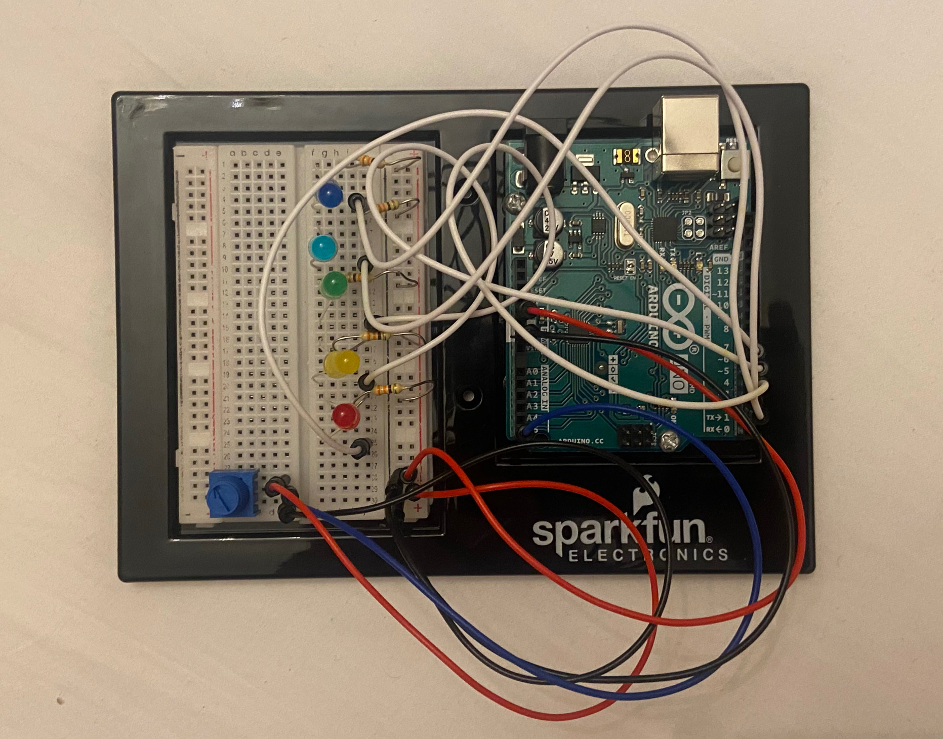
Design and Circuit
Still kind of stuck on what more to add to the bottom half of the p5 design, so it’s still subject to change!
Arduino circuit is done, but still trying to see if I can fit making a cardboard/ wood covering in time.
Note:
I need to lengthen the potentiometer diodes as they aren’t as tall as the LEDs’ diodes (I want to make a simple cardboard covering that hides everything but the potentiometer and the LEDs– basically anything that isn’t going to be used by the user).
Updates
I added variables that would encompass the ranges on both Arduino and p5, so instead of the designated range numbers from 0-1023 popping up, the numbers 0-6 would pop up for each input in the serial monitor on p5/ Arduino.
In p5, this is written in if statements:
else if (inData == GREEN) {

greenSongs(); // calls function that plays songs
// replace with randomized array?

noStroke();
fill (128,172,57); // text color
textFont(radioFont, 45); // (font name, font size)
text("CLASSIC ROCK", 142, 148); // (text, x, y)
glow(color(128,172,57), 19); // calls glow function

}
In Arduino, this is done by simply adding the integer currentColor which would equal each value from 0-6 depending on what the potentiometer value is. For example:
The music was being played in function draw (), so it started to play in an infinite loop. I tried to fix this by adding another function that plays the music when draw calls it, but that didn’t work. The song just keep playing a thousand times per second and became inaudible.
I might cut up a wooden or cardboard slab to cover all the wires, but I don’t know if I’ll have time to do that until I figure out the software of playing the music files without them being on a loop.
As of this week, we had some tweaks to the concept of our whole idea. The idea will now center on connecting two people and two lamps to a single computer. This week has been filled with a range of challenges that have put our knowledge of Arduino and p5js to the test. Integrating a touch sensor to send data from Arduino to p5js and collecting and transmitting several bytes of information from p5js to Arduino are some examples of the operations that fall under this category. Among the concept adjustments we made was to use regular wire serial communication between Arduino and p5js rather than relying on the use of a bluetooth module, which would have made the project more interesting.
PROGRESS
At the moment we are struggling with successfully sending RGB values from p5js to Arduino and eventually displaying them on the LED strip. As of now, when we transmit specified color values from p5js to Arduino, they are displayed on the LED strip as intended. However, only the color white is projected on the LED strip when we send any other RGB values. Additionally, the lights do not “cycle” through their respective patterns like they should. For example, when we chose “flicker”, the lights flicker once and remain off, instead of flickering continuously as intended in the Arduino code. We started by doing a number of comprehensive tests to rule out the possibility that the issue could be with the serial transmission. The only remaining hypotheses for the bugs that we are still investigating are if the problem could be caused by using the jpg color wheel to determine color values or whether there are more mechanisms involving how Arduino interacts with LED strips that we need to comprehend. The below is a compilation of test-related videos:
(lights only showing white and not looping continuously)
(testing the color printed in the console vs the color that appeared to be chosen from the wheel and seeing that they two colors do not match up)
SOLUTION
After several hours of debugging, we found that using an image to pick the color just wasn’t working. We determined our hypothesis to be correct – that the issue was the values being sent by p5.js.
The mouse position was taking pixels from the original image and it was not being remapped to the resized and re positioned image we had in our code, even after applying the map function and several iterations of repositioning/resizing the image. We believe that the example used ( link ) to create the color picker worked because the image IS the canvas, which is not the case for ours.
We decided on a new way for the user to select the color, which would be by having an object that flashes a different color every few seconds where the user can then press a key to “freeze” the object on the selected color. In our updated sketch, all possible colors have been predetermined by us, though the process of choosing the color is more engaging now.
After making this change, the values sent to Arduino were actually representative of the color that was chosen when pressing a key, and the color that is displayed on the LED’s is now accurate. However, this did not solve the issue of the lights not looping.
As of this week, we had some tweaks to the concept of our whole idea. The idea will now center on connecting two people and two lamps to a single computer. This week has been filled with a range of challenges that have put our knowledge of Arduino and p5js to the test. Integrating a touch sensor to send data from Arduino to p5js and collecting and transmitting several bytes of information from p5js to Arduino are some examples of the operations that fall under this category. Among the concept adjustments we made was to use regular wire serial communication between Arduino and p5js rather than relying on the use of a bluetooth module, which would have made the project more interesting.
PROGRESS
At the moment we are struggling with successfully sending RGB values from p5js to Arduino and eventually displaying them on the LED strip. As of now, when we transmit specified color values from p5js to Arduino, they are displayed on the LED strip as intended. However, only the color white is projected on the LED strip when we send any other RGB values. We started by doing a number of comprehensive tests to rule out the possibility that the issue could be with the serial transmission. The only remaining hypotheses for the bugs that we are still investigating are if the problem could be caused by using the jpg color wheel to determine color values or whether there are more mechanisms involving how Arduino interacts with LED strips that we need to comprehend. The below is a compilation of test-related videos:
SOLUTION
After several hours of debugging, we found that using an image to pick the color just wasn’t working. We determined our hypothesis to be correct – that the issue was the values being sent by p5.js.
The mouse position was taking pixels from the original image and it was not being remapped to the resized and re positioned image we had in our code, even after applying the map function and several iterations of repositioning/resizing the image. We believe that the example used ( link ) to create the color picker worked because the image IS the canvas, which is not the case for ours.
We decided on a new way for the user to select the color, which would be by having an object that flashes a different color every few seconds where the user can then press a key to “freeze” the object on the selected color. In our updated sketch, all possible colors have been predetermined by us, though the process of choosing the color is more engaging now.
After making this change, the values sent to Arduino were actually representative of the color that was chosen when pressing a key, and the color that is displayed on the LED’s is now accurate. However, this did not solve the issue of the lights not looping.
For this final project, I will be working with Ahmed as a group. We decided to go with our initial idea of making an interactive art piece. However, we considered what Professor Shiloh advised us during class when we shared our idea and started thinking about how we can make it more interactive and not lose the attention of our audience in 5 seconds. Before we started thinking more creatively, we were set on just making an art piece inspired by graphic art. Ahmed’s first post on this concept is linked here.
The art piece looks as if you are looking from above into a room filled with interactive walls. This digital art interacts with the user through mouse or sound control. Initially, we just wanted to replicate this same idea using p5.js and Arduino and make it come to life with materials in the IM Lab.
However, after taking into consideration what Professor Shiloh told us, which was that it would only keep the user entertained for a maximum of five seconds and need to come up with a way to make it more engaging, we did just that.
First, no more boring colorful blocks that look like walls. To be more aligned with our initial theme of depicting a living, breathing, organisms that reacts to different inputs, we have a more specific theme now: Stranger Things. If you are not familiar with stranger things, below is a trailer to season 1.
There are 4 seasons of stranger things now. The monsters that the group of kids fight are living, breathing organisms of some kind. The main things you and the user need to know is that one of the monsters on the show is called a Demogorgon. Below is a picture. The picture shows how it looks when it’s head is closed versus when it is open.
Closed Head vs Open Head (middle guy)
It kinds of looks like a very scary version of the Venus Flytrap plant.
At first, we were thinking of a plant/nature theme where we would depict some type of garden or collection of ferns or Venus Flytraps interacting with each other. It would have been more on the pretty nature side of things, but we thought Stranger Things could spice things up a little. We started looking for inspiration and we found this 3-D printed Demogorgon. We will only 3-D print the head and it would sit upright on the board we built. We plan on having the heads open and close as the user interacts with them through different mediums.
3-D printed Demogorgon. Inspiration.
Our interactive Demogorgon project will include speakers playing ominous music, flex sensors, an ultrasonic sensor, and big flaps of the monster’s head being controlled with Servo motors. Using these components, the user will be able to interact with the living, breathing Demogorgons and have a little fun with them.
To make the whole project even more immersive we created a narrative behind the Demogorgon and the user being able to choose to interact with it as the protagonist or the antagonist.
Description of Arduino program will do with each input and output and what it will send to and/or receive from P5
Using Adruino, we will be controlling the Servo Motors, and checking for any analog inputs from the flex and ultrasonic sensors. The sensor values are mapped to (0, 180) using the following section of code:
  OutsideFlexValue = analogRead(OutsideFlexPin);
  delay(15); //adding slight delays to make it stable

  InnerFlexValue = analogRead(InsideFlexPin);
  delay(15);

  servoPositionOutside = map(OutsideFlexValue, 24, 48, 45, 180);  // need it to rest at a midwards position

// int round10(int servoPositionOutside);

  servoPositionInside = map(InnerFlexValue, 24, 48, 45, 180);
It will send out a signal to the p5js program every time it hits a pre-determined threshold value. The out-sent value is to let the P5Js code know to play a growling sound along with the petals opening wide.
Description of what the P5 program will do and what it will send to and/or receive from Arduino
In order for the user to control or choose the interaction they would like to have with the Demogorgon, we will use p5.js. We will display an instruction screen followed by a digital button screen where the user can select presets and change between modes. For instance, the user will be able to choose between using the flex sensors with the glove or with the ultrasonic distance sensors to have different interactions with each.
From arduino it will receive the aforementioned serial communication to let it know when to play certain sounds.
Future Improvements:
Need to work on the mechanical aspect of the project more. The initial testing has shown that the servo motors cannot be used with a large armature due to force constraints.
The main problem we had from the start was that there was a lot of interference from the 5v pin on the Arduino which was causing the motors connected in parallel to jitter even when they were not being activated. We tried changing wires, changing components, making the digital pins far away as possible, and even using a different board but none of it worked.
Solution: The solution as the professor suggested was to use a separate battery to operate the servos with only digital PWM pins being connected to the board itself. This reduced the jitter to negligible.
As of now, the test mode can be enabled with the below modification:
function draw() {
  if (!serialActive) {   // serialActive  -->  !serialActive
    ...
  }
}
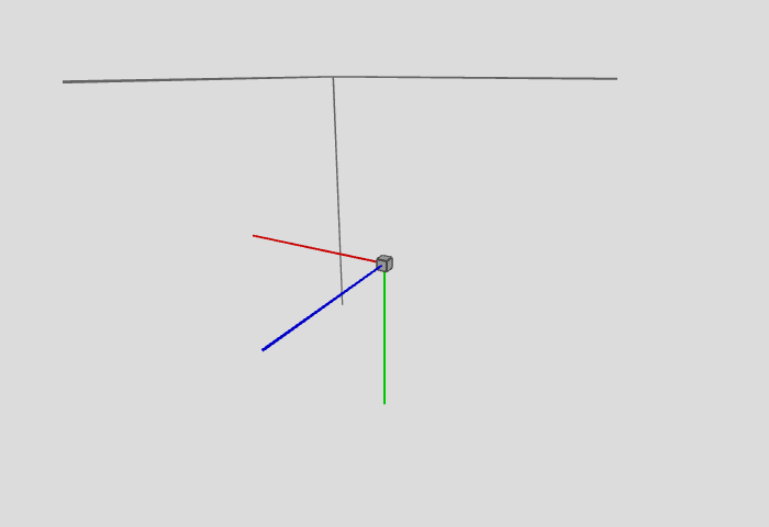
Use wheel click or right click + Esc to interact with the canvas. Left click will trigger setUpSerial(). Use arrow keys to change perspective (rotation angle of entire drawing). Use numpad (123 789) to control x, y, z coordinate of the drawing block.
Progress (Dec 6, 2022): p5.js
Test mode can be enabled with the following modification:
let debug = true;
Use Ctrl + F and find variable debug to see which interactions are implemented in debug mode.
The physical controller is in the process of being built.
Group
I will be likely working as solo, although I am open to anyone who can help me with the physical side of the project.
For this final project, I will be working with Abigail as a group. We decided to go with our initial idea of making an interactive art piece. However, we considered what Professor Shiloh advised us during class when we shared our idea and started thinking about how we can make it more interactive and not lose the attention of our audience in 5 seconds. Before we started thinking more creatively, we were set on just making an art piece inspired by graphic art. My first post on this concept is linked here.
The art piece looks as if you are looking from above into a room filled with interactive walls. This digital art interacts with the user through mouse or sound control. Initially, we just wanted to replicate this same idea using p5.js and Arduino and make it come to life with materials in the IM Lab.
However, after taking into consideration what Professor Shiloh told us, which was that it would only keep the user entertained for a maximum of five seconds and need to come up with a way to make it more engaging, we did just that.
First, no more boring colorful blocks that look like walls. To be more aligned with our initial theme of depicting a living, breathing, organisms that reacts to different inputs, we have a more specific theme now: Stranger Things. If you are not familiar with stranger things, below is a trailer to season 1.
There are 4 seasons of stranger things now. The monsters that the group of kids fight are living, breathing organisms of some kind. The main things you and the user need to know is that one of the monsters on the show is called a Demogorgon. Below is a picture. The picture shows how it looks when it’s head is closed versus when it is open.
Closed Head vs Open Head (middle guy)
It kinds of looks like a very scary version of the Venus Flytrap plant.
At first, we were thinking of a plant/nature theme where we would depict some type of garden or collection of ferns or Venus Flytraps interacting with each other. It would have been more on the pretty nature side of things, but we thought Stranger Things could spice things up a little. We started looking for inspiration and we found this 3-D printed Demogorgon. We will only 3-D print the head and it would sit upright on the board we built. We plan on having the heads open and close as the user interacts with them through different mediums.
3-D printed Demogorgon. Inspiration.
Our interactive Demogorgon project will include speakers playing ominous music, flex sensors, an ultrasonic sensor, and big flaps of the monster’s head being controlled with Servo motors. Using these components, the user will be able to interact with the living, breathing Demogorgons and have a little fun with them.
To make the whole project even more immersive we created a narrative behind the Demogorgon and the user being able to choose to interact with it as the protagonist or the antagonist.
Description of Arduino program will do with each input and output and what it will send to and/or receive from P5
Using Adruino, we will be controlling the Servo Motors, and checking for any analog inputs from the flex and ultrasonic sensors. The sensor values are mapped to (0, 180) using the following section of code:
  OutsideFlexValue = analogRead(OutsideFlexPin);
  delay(15); //adding slight delays to make it stable

  InnerFlexValue = analogRead(InsideFlexPin);
  delay(15);

  servoPositionOutside = map(OutsideFlexValue, 24, 48, 45, 180);  // need it to rest at a midwards position

// int round10(int servoPositionOutside);

  servoPositionInside = map(InnerFlexValue, 24, 48, 45, 180);
It will send out a signal to the p5js program every time it hits a pre-determined threshold value. The out-sent value is to let the P5Js code know to play a growling sound along with the petals opening wide.
Description of what the P5 program will do and what it will send to and/or receive from Arduino
In order for the user to control or choose the interaction they would like to have with the Demogorgon, we will use p5.js. We will display an instruction screen followed by a digital button screen where the user can select presets and change between modes. For instance, the user will be able to choose between using the flex sensors with the glove or with the ultrasonic distance sensors to have different interactions with each.
From arduino it will receive the aforementioned serial communication to let it know when to play certain sounds.
Future Improvements:
Need to work on the mechanical aspect of the project more. The initial testing has shown that the servo motors cannot be used with a large armature due to force constraints.
The main problem we had from the start was that there was a lot of interference from the 5v pin on the Arduino which was causing the motors connected in parallel to jitter even when they were not being activated. We tried changing wires, changing components, making the digital pins far away as possible, and even using a different board but none of it worked.
Solution: The solution as the professor suggested was to use a separate battery to operate the servos with only digital PWM pins being connected to the board itself. This reduced the jitter to negligible.


