
Concept:
My idea was to use the photoresistor as an analog sensor to control how a group of LEDs display. With a decrease in resistance as a result of lumen capacity, the photoresistor controls the LEDs to output a pattern of light displays which spells “ON”. Whereas with high resistance due to less lumen capacity, the LEDs output in a pattern which spells “OFF” with a missing F due to space.
The change between “ON” and “OFF” is controlled by two LEDs which read the analog value of the photoresistor and output a scaled down value of it.
The code:
int g1 = 12;
int g2 = 11;
int fOn = 8;
int fOff = 7;
int sens = A0;
int sensVal;
int ledval;

void setup() {
  // put your setup code here, to run once:
  pinMode(g1, OUTPUT);
  pinMode(g2, OUTPUT);
  pinMode(A0, INPUT);
  Serial.begin(9600);
}

void loop() {
  // put your main code here, to run repeatedly:
  sensVal = analogRead(sens);
  ledval = (255./1023.) * sensVal;
  Serial.println(sensVal);
  delay(250);
  if(sensVal < 200){
    digitalWrite(g1, HIGH);
    digitalWrite(g2, HIGH);
    analogWrite(fOn, ledval);
    digitalWrite(fOff, LOW);
  }
  else{
    digitalWrite(g1, HIGH);
    digitalWrite(g2, HIGH);
    analogWrite(fOff, ledval);
    digitalWrite(fOn, LOW);
  }

}
The “ON” state display:
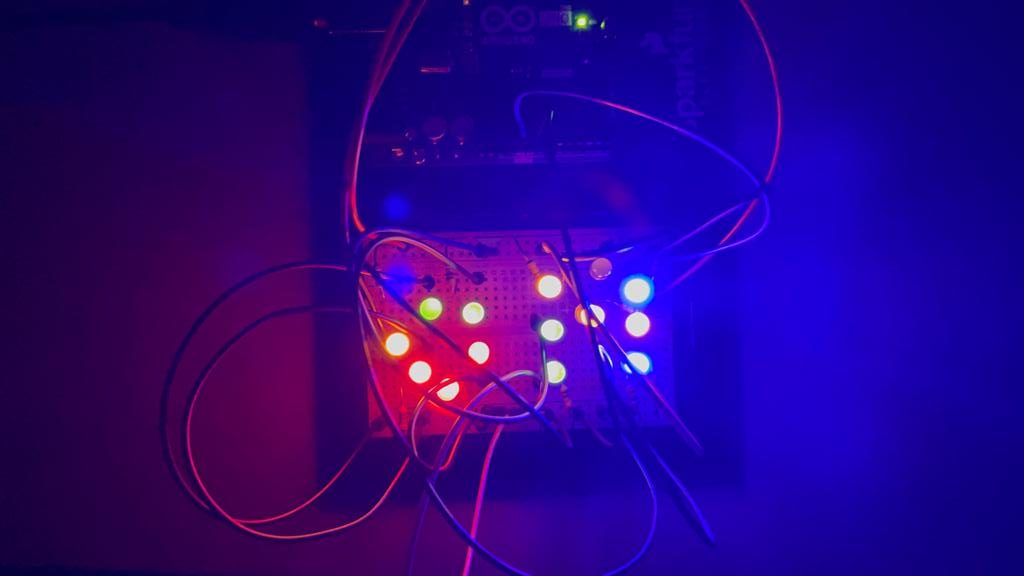
The “OFF” state display:
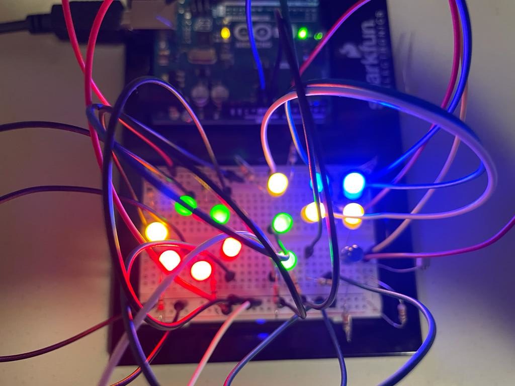
When the lights are on the leds display on and when the lights are off the leds display off.
The video demonstration:
Reflections:
It was challenging to set up the LEDs group them together to display. With a little try and error and schematic, I got them to work. I plan to add sound and other output signals to signify when the lights are out.
My attempt at adding sound: