Inspiration 🚘:
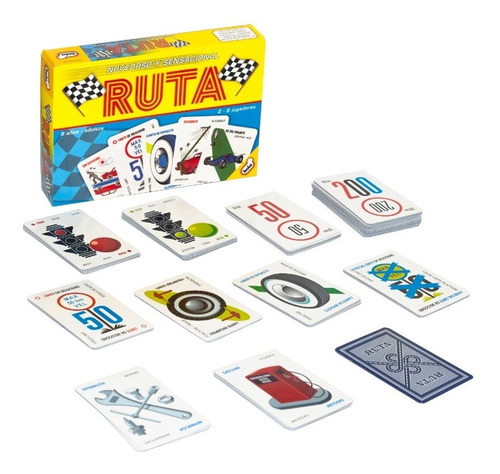
When faced with the use of both analog and digital sensors, my mind initially went to cars. Especially their interface right in front of the steering wheel that indicates fuel, if lights are turned on or off, speed, and many other components. I imagine they must use both, digital and analog circuits, for all these LED’s and indicators. And thus, decided to build my own. Throughout my brainstorm process I was also reminded of Ruta, my favorite card game. In this board game, you need a green light card to signify the car running. A yellow/red light would indicate you could not drive, nor obtain points.
Building Process 🚧:
Going off from this concept, I placed three LED’s, a red one, a yellow one, and a green one in the shape of a stoplight. This would be my visualization of the car running or not. I then added three elements that are crucial for driving successfully:
-
-
- Pressing the Accelerator
- Adjusting the Steering Wheel
- Turning on the Headlights if it’s dark
-
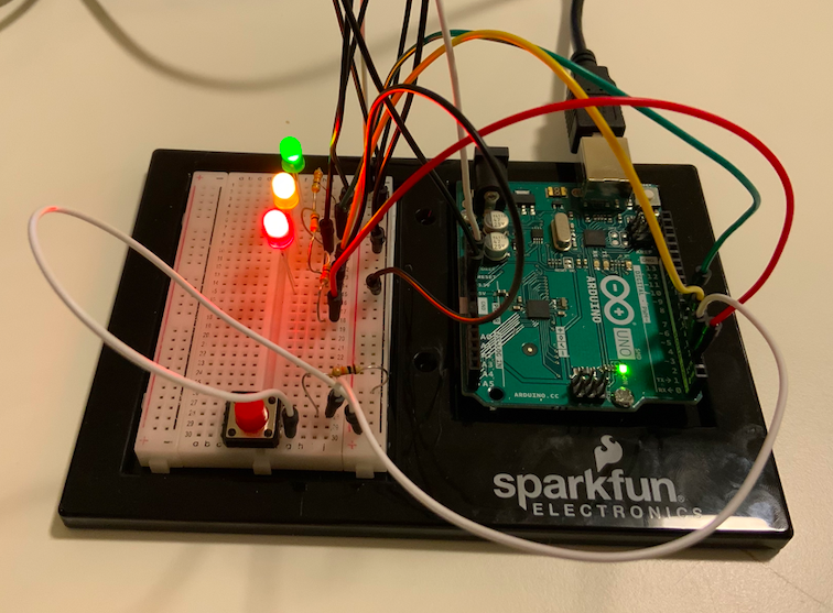
With these requirements, I built the following:
-
-
- A digital circuit for the red light. It is on, only if you press on the red button, which represents the gas pedal.
- A circuit with an analog sensor for the yellow LED. It will blink unless the steering wheel, a potentiometer, is oriented towards the right side, in which it will be turned off.
- An analog circuit with the Blue LED light. It will light up as per the light it receives from the photosensor.
- IF the light received passes a certain threshold, the accelerator is pressed, and the steering wheel is facing the correct way, the green light will turn on, and you will be on your way!
-
Here is my Code:
const int greenPin = 7;
const int yellowPin = 4;
const int redPin = 2;
const int buttonPin = 3;
const int wheelPin = 8;
const int bluePin = 9;
unsigned long timer = 0;
bool onOff = LOW;

void setup() {
  Serial.begin(9600);
 pinMode(greenPin, OUTPUT);
 pinMode(yellowPin, OUTPUT);
 pinMode(redPin, OUTPUT);
 pinMode(bluePin, OUTPUT);
 pinMode(buttonPin, INPUT);

}

void loop() {
bool redState = digitalRead(redPin);
bool yellowState = digitalRead(yellowPin);

// RED //
byte buttonState = digitalRead(buttonPin);

if (buttonState == HIGH) {
  digitalWrite(redPin, LOW);
} else
{digitalWrite(redPin, HIGH);}
// RED//

//YELLOW//
int wheelValue = analogRead(A0);
int mappedValue = map(wheelValue, 0, 1023, 0, 255);


if (mappedValue > 110 && mappedValue < 140) {
  digitalWrite(yellowPin, LOW);
} else {

 if(millis()>timer){
      onOff = !onOff;
      timer = millis() + 200;
      digitalWrite(yellowPin, onOff);
      }
      }

//YELLOW//


// BLUE //
int lightValue = analogRead(A1);
int mappedLightValue = map(lightValue, 655, 1000, 0, 255);
int constrainedValue = constrain(mappedLightValue, 0, 255);

analogWrite(bluePin, constrainedValue);
//Serial.println(lightValue);
// BLUE //

// GREEN //
if (redState == LOW && yellowState == LOW && mappedValue > 110 && mappedValue < 140 && constrainedValue > 200){

 digitalWrite(greenPin, HIGH);
} else {
  digitalWrite(greenPin, LOW);
  }
// GREEN //

}
Initially, I had the yellow LED to blink at a speed determined by the analog input of the potentiometer. The higher the value, the fastest the blinking. However, this gave the project an unorganized structure and distracted the user from the goal of turning on the car. Thus, I gave it a set value.
Another important thing to note is that during the day, the blue LED will always be turned on. This is intentional, and is used to signify how headlights are only needed at night. If you wish to change this, alter the mappedLightValue variable and make the 655 higher to a threshold of about 950+.
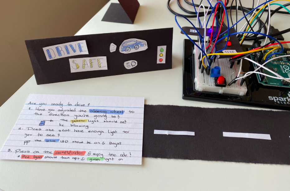
Final Product 🚨:
I am very happy with how Drive Safe turned out. After I completed the circuit, I made some decorations to make it look cleaner and easier to understand. I have tested it multiple times, in multiple scenarios and it seems to work perfectly fine. I also wrote a set of instructions for anyone using it without me.
In the future, I would like to experiment with other type of sensors, and figure out a way to make cables not visible, as they damage the aesthetic quality of the piece a lot.