
EXERCISE 1 :
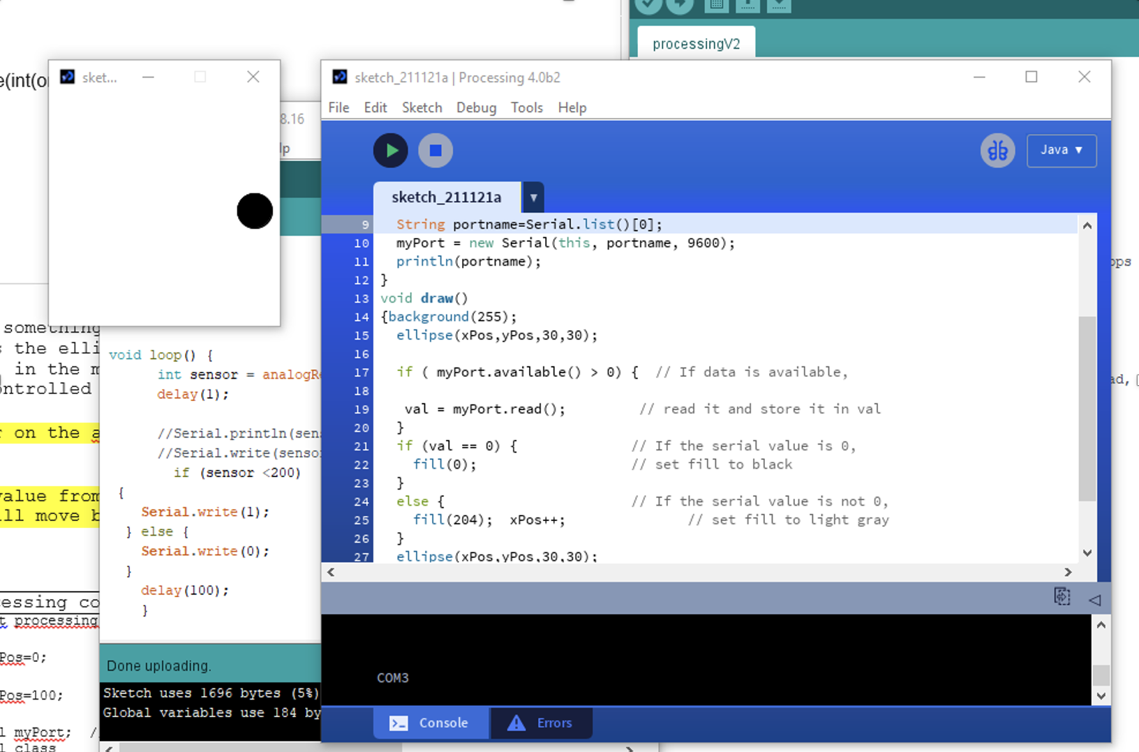
Procedure – The sensor on the Arduino Is the LDR, light depending on resistor. So, once the value from the LDR Arduino is less than 200, the ellipse will move by adding 1 to the Xposition.
Challenges- The difficulty was in working using both processing and Arduino together to be able to read from Arduino and control processing ellipse. By using myport to create an object from serial reading in processing , the problem was solved.
PROCESSING CODE :
import processing.serial.*;
int xPos=0;
int yPos=100;
Serial myPort;  // Create object from Serial class
int val;      // Data received from the serial port

void setup(){
  size(200, 200);
  String portname=Serial.list()[3];
  myPort = new Serial(this, portname, 9600);
  println(portname);
}
void draw()
{background(255);
  ellipse(xPos,yPos,30,30);

  if ( myPort.available() > 0) {  // If data is available,

   val = myPort.read();         // read it and store it in val
  }
  if (val == 0) {              // If the serial value is 0,
    fill(0);                   // set fill to black
  }
  else {                       // If the serial value is not 0,
    fill(204);  xPos++;               // set fill to light gray
  }
  ellipse(xPos,yPos,30,30);
}
ARDUINO CODE :
void setup() {
  Serial.begin(9600);

}

void loop() {
      int sensor = analogRead(A0);
      delay(1);

      //Serial.println(sensor);
      //Serial.write(sensor);
        if (sensor <200)
 {
    Serial.write(1);               // send 1 to Processing
  } else {
    Serial.write(0);               // send 0 to Processing
  }
    delay(100);
    }
OUTPUT :
EXERCISE 2 :
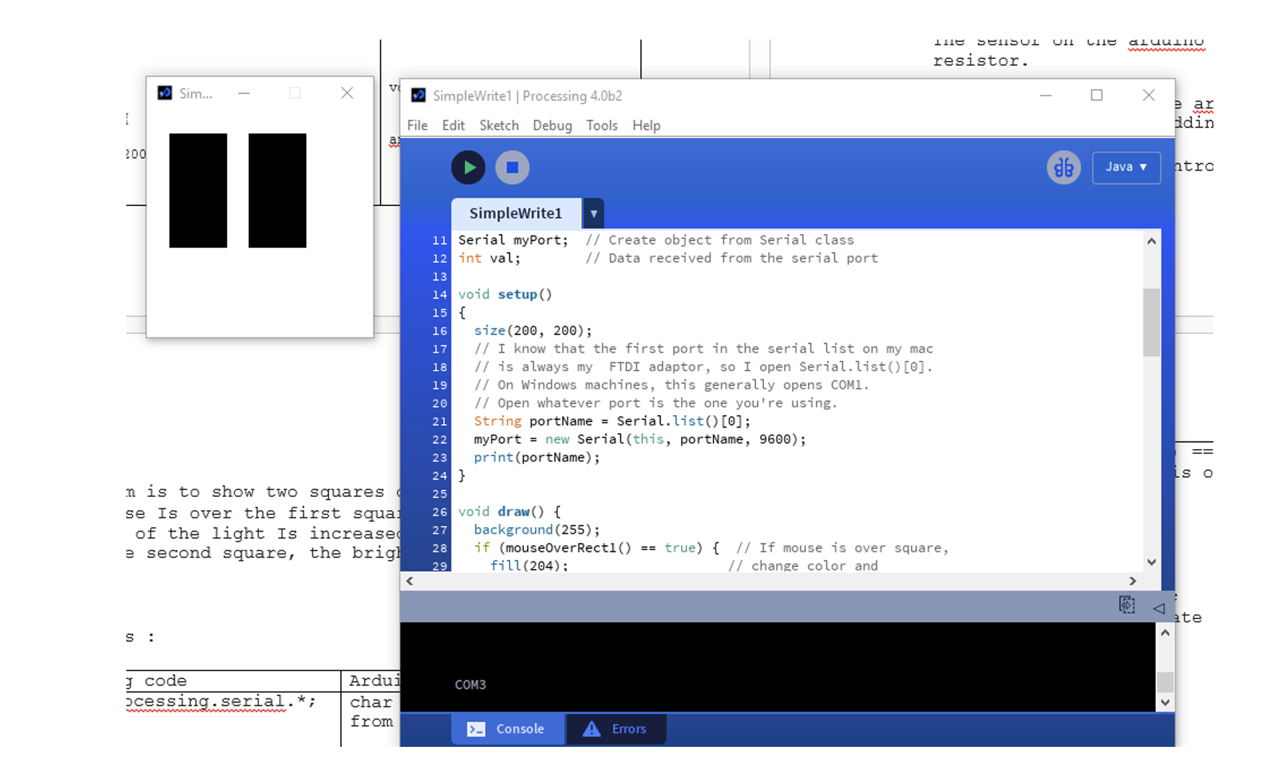
Procedure – The program is to show two rectangles on processing screen. If the mouse is over the first square on the left, the brightness of the light is increased by 1 and if the mouse is over the second square, the brightness is less by 1. The analogWrite(ledPin,i) is the command used for controlling the brightness of the led.
Challenges- The hardship was to connect the serial to write to the Arduino. By creating 2 different rectangles, we had two options for increasing and decreasing the brightness of the light.
PROCESSING CODE :
import processing.serial.*;

Serial myPort;  // Create object from Serial class
int val;        // Data received from the serial port

void setup()
{
  size(200, 200);
  String portName = Serial.list()[3];
  myPort = new Serial(this, portName, 9600);
  print(portName);
}

void draw() {
  background(255);
  if (mouseOverRect1() == true) {  // If mouse is over square,
    fill(204);                    // change color and
    myPort.write('H');              // send an H to indicate mouse is over square
  }
  else {                        // If mouse is not over square,
    fill(0);                      // change color and
    //myPort.write('L');              // send an L otherwise

  if (mouseOverRect2() == true) {  // If mouse is over square,
    fill(204);                    // change color and
    myPort.write('L');              // send an H to indicate mouse is over square
  }
  else {                        // If mouse is not over square,
    fill(0);                      // change color and
    //myPort.write('N');              // send an L otherwise
  }}
  rect(20, 20, 50, 100);         // Draw a square
  rect(90, 20, 50, 100);
}

boolean mouseOverRect1() { // Test if mouse is over square
  return ((mouseX >= 30) && (mouseX <= 70) && (mouseY >= 20) && (mouseY <= 120));
}
boolean mouseOverRect2() { // Test if mouse is over square
  return ((mouseX >= 90) && (mouseX <= 140) && (mouseY >= 20) && (mouseY <= 120));
}
ARDUINO CODE :
char val; // Data received from the serial port

int ledPin = 13; // Set the pin to digital I/O 4

int i = 10;

void setup() {

pinMode(ledPin, OUTPUT); // Set pin as OUTPUT

Serial.begin(9600); // Start serial communication at 9600 bps

}

 void loop() {

while (Serial.available()) { // If data is available to read,

val = Serial.read(); // read it and store it in val

if (val == 'H') { // If H was received
i++;
analogWrite(ledPin,i);

}
else if (val == 'L'){
i--;
analogWrite(ledPin,i); // Otherwise turn it OFF


}

delay(100); // Wait 100 milliseconds for next reading
}
}
OUTPUT :
EXERCISE 3 :
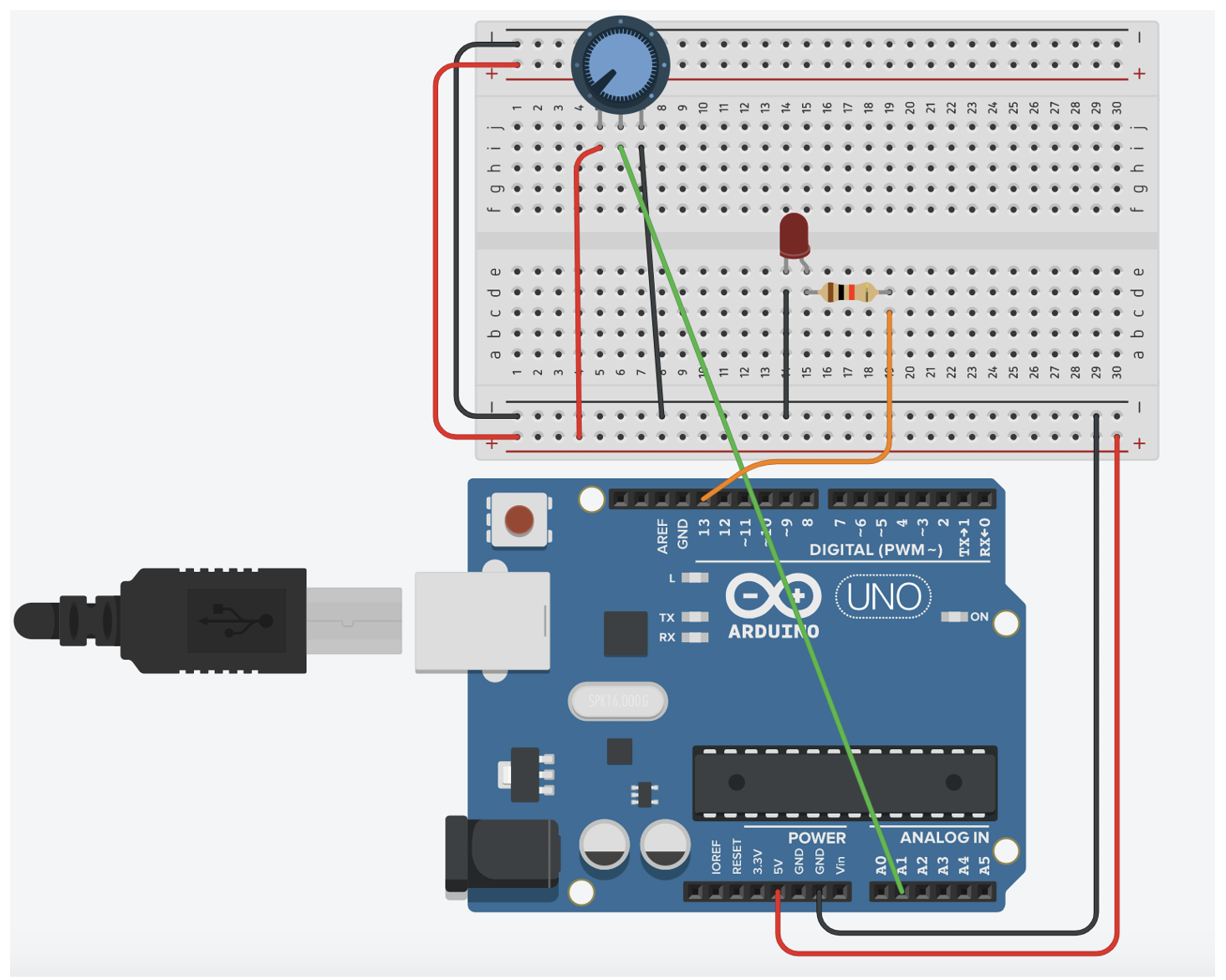
Procedure – The analog sensor used is the potentiometer on A1 analog port 1. If the value is less than 1024/2, the wind is blowing to the right. If the value is higher, then the wind is blowing to the left. Thus, the light turns on when the ball is bouncing.
Challenges- The challenge is to turn on the LED to have it on during the bouncing of the ball on processing screen. The second challenge was to use one analog sensor to make right and left movement, so our solution was to use a potentiometer that reads values from 0 to 1023. The mid value is the threshold, if under 1023/2, it moves to the right side, and if higher, moves to left side
PROCESSING CODE :
import processing.serial.*;

Serial myPort;  // Create object from Serial class
int val;
PVector velocity;
PVector gravity;
PVector position;
PVector acceleration;
PVector wind;
float drag = 0.99;
float mass = 50;
float hDampening;

void setup() {
  size(640,360);
  noFill();
  position = new PVector(width/2, 0);
  velocity = new PVector(0,0);
  acceleration = new PVector(0,0);
  gravity = new PVector(0, 0.5*mass);
  wind = new PVector(0,0);
  hDampening=map(mass,15,80,.98,.96);
  String portName = Serial.list()[3];
  myPort = new Serial(this, portName, 9600);
}

void draw() {
  background(255);
  //if (!keyPressed){
   // wind.x=0;
  //  velocity.x*=hDampening;
 // }
  applyForce(wind);
  applyForce(gravity);
  velocity.add(acceleration);
  velocity.mult(drag);
  position.add(velocity);
  acceleration.mult(0);
  ellipse(position.x,position.y,mass,mass);
  //
  if (position.y > height-mass/2) {
      velocity.y *= -0.9;  // A little dampening when hitting the bottom
      position.y = height-mass/2;
      myPort.write('L');
    }
    else myPort.write('H');

  if ( myPort.available() > 0) {  // If data is available,
    val = myPort.read();         // read it and store it in val
  }

     if(val==0){
    wind.x=-1;
  }

   else{
    wind.x=1;
  }
}

void applyForce(PVector force){
  // Newton's 2nd law: F = M * A
  // or A = F / M
  PVector f = PVector.div(force, mass);
  acceleration.add(f);
}

void keyPressed(){
  if (keyCode==LEFT){

    wind.x=-1;
  }
  if (keyCode==RIGHT){

    wind.x=1;
  }
  if (key==' '){
    mass=random(15,80);
    position.y=-mass;
    velocity.mult(0);
  }
}
ARDUINO CODE :
char val; // Data received from the serial port

int ledPin = 13; // Set the pin to digital I/O 4

int i = 50;
int left = 0;
int right = 0;
int rightbool=0;
void setup() {

pinMode(ledPin, OUTPUT); // Set pin as OUTPUT

Serial.begin(9600); // Start serial communication at 9600 bps

}

 void loop() {

while (Serial.available()) { // If data is available to read,

val = Serial.read(); // read it and store it in val

}

if (val == 'H') { // If H was received

digitalWrite(ledPin,HIGH);

} else {

digitalWrite(ledPin,LOW); // Otherwise turn it OFF

}
int sensor = analogRead(A1);
//Serial.println(sensor);
if(sensor<511){rightbool=1; Serial.write(1);}
else {rightbool=0;Serial.write(0);}

delay(100); // Wait 100 milliseconds for next reading

}
CIRCUIT DIAGRAM:
You removed the handshake. I made a big emphasis about not doing this in class, and you can tell in your video that the bounces don’t work properly. Always a good idea to include a handshake when doing serial communication