
CATS PARTY
INTRODUCTION:
In week 10, I have continued working with Arduino hardware and got an in-depth understanding of both the analog and digital inputs. For my project, I had to use at least one analog and one digital sensor to control at 10 LEDs in some creative manner. So, I decided to use the proximity sensor as my digital sensor and the potentiometer as my analog sensor to control 5 LED’s each in a respective manner that creates light mashups.
INSPIRATION:
The inspiration behind the usage of different LED's is their colorful and attractive appearance which in my case would give a disco themed party. They light up the room in a distinctive manner providing the crowd with a lighthearted experience. Generally speaking, colors often provide a joyful emotion, and an ideal manner to execute this is was by using LED's as an inspiration. In this project, the aim is to mimic those lights on a smaller scale using arduino. The usage of the cat theme came as an inspiration from my sister's love of cats as well as the well-loved campus cats. It provides a fun twist to the project result and appearance, as well as personalizes it in a creative and unique manner.
IdEA OVERVIEW IMPLEMEnTAtION:
Once I grasped the notion of working with both the analog and digital sensor, I decided to make a unique led pattern with it. This implies that I can compare them with a progressive volume or fuel level indicator using the LED’s. To start off, I used 5 LEDs each for analog and digital sensor (total 10 LED’s). With the digital sensor, by default all the LEDs are off and as I place my hand on the proximity sensor, the LEDs switch on one by one till all 5 are lit up. So basically, I can swipe my hand on the sensor and turn on 1 LED, 2 LED or 3 LED as per the number of swipes on the sensor or time duration for which the hands are on the sensor. Later, when all the LEDs are on, any further swipe over the proximity sensor will result in resetting all the LEDs and they will then again start from the all off state. On the other hand, with the analog sensor, again all LEDs are off and as I turn my potentiometer the LEDs start switching on. From all off at one end, the LEDs light up one by one till all are on to the other end. In other words, this can be compared to a volume control knob on older TV’s or music players on vehicles where one end is mute and other end is max volume.
CHALLENGES & PROBLEMS:
In this week, I had decided to use the proximity sensor as a digital sensor. For that, I used one which I have ordered via amazon. Then, although working with the analog sensor was quite straight forward, I had to divide the output of the analog sensor into different ranges as per my concept. This have taken some time for me to comprehend it and the conversion of the ADC value from 0V - 5V to 0 – 1023 has required some effort and additional readings. One thing that aided my process was watching a few YouTube videos for the ADC value conversion concept.
PROCEDURE:
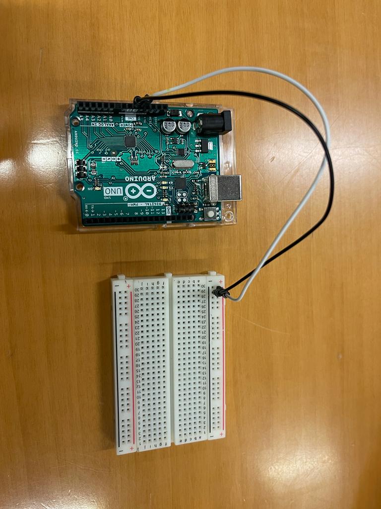
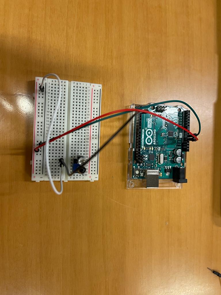
First, I used the Arduino board to power the + and – rails of the breadboard so that the entire circuit can use + and – from these rails whenever required in future connections. In the following image, a jumper wire goes into the +ve rail and the other goes into the -ve rail.
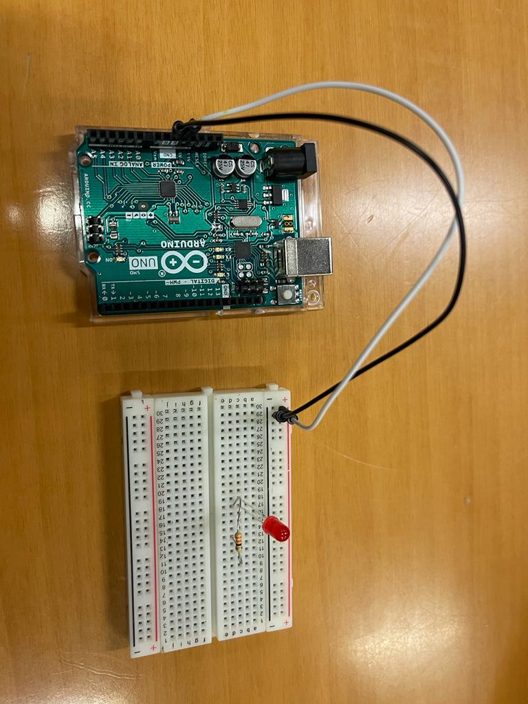
Having already connected the LED in the last assignment, I have quickly completed the following circuit and the anode of LED (longer leg) was connected to Arduino D7 and the resistor was connected to the ground rail as shown below.
I tested the simple LED circuit by uploading the following code and it have worked.
// C++ code

//it runs only once

void setup()
{
  //pinmode is used to configure pin number 7 as an output
  pinMode(7, OUTPUT);
}

// runs forever
void loop()
{
  //writing a logic high which equals 5 volt or 1 in binary
  //jumper wire connected to anode, LED switch on
  digitalWrite(7, HIGH);
  delay(1000); // Wait for 1000 millisecond(s)

  //writing a logic low which equals  0 in binary
  //jumper wire connected to anode, LED switch off
  digitalWrite(7, LOW);
  delay(1000); // Wait for 1000 millisecond(s)
}
The video shown below was the output !
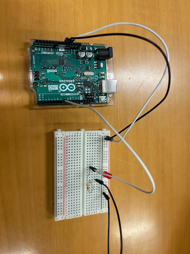
Next, I wanted to test the digital sensor with a single LED, so I have connected the sensor on breadboard and powered it with the onboard power rails. I connected the output of sensor to digital pin 7 which was configured as an input. Moreover , I have utilized the following code and the output was as shown in video below.
// C++ code


void setup()
{
  //pinmode is used to configure pin number 7 as an output
  pinMode(7, OUTPUT);
  //configuring 6 as input to read data from external switch/ sensor
  pinMode(6,INPUT);
}

void loop()
{
  //LED switch off

  if(digitalRead(6)==LOW)
  {
    // LED switch on
    digitalWrite(7, HIGH);
  }
  else
  {
    // LED switch off
    digitalWrite(7, LOW);
  }
Then, I moved on to the connection of the digital proximity sensor with 5 LED’s. I removed the earlier LED and disconnected the sensor output pin. Now, only the power rails were connected to the respective pins as shown.
Next, I started to connect a single LED. All the other LED’s were kept ready to be placed on the breadboard.
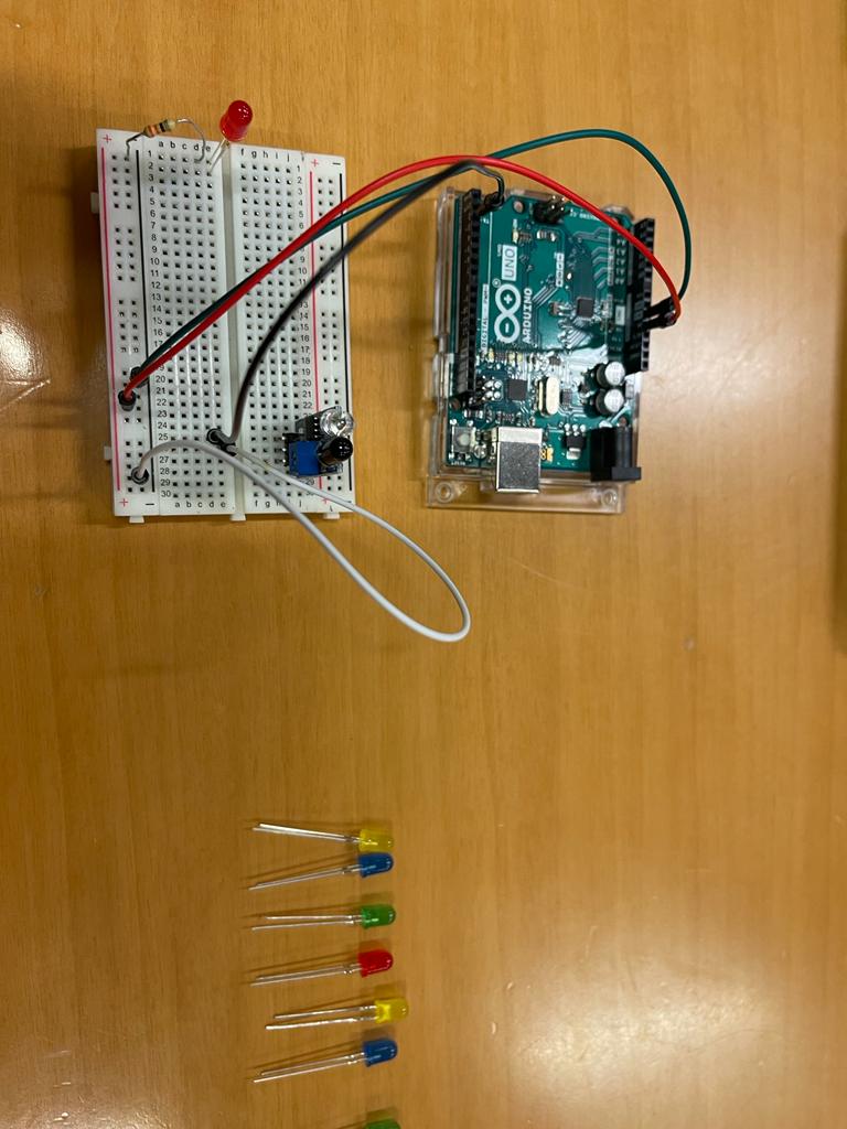
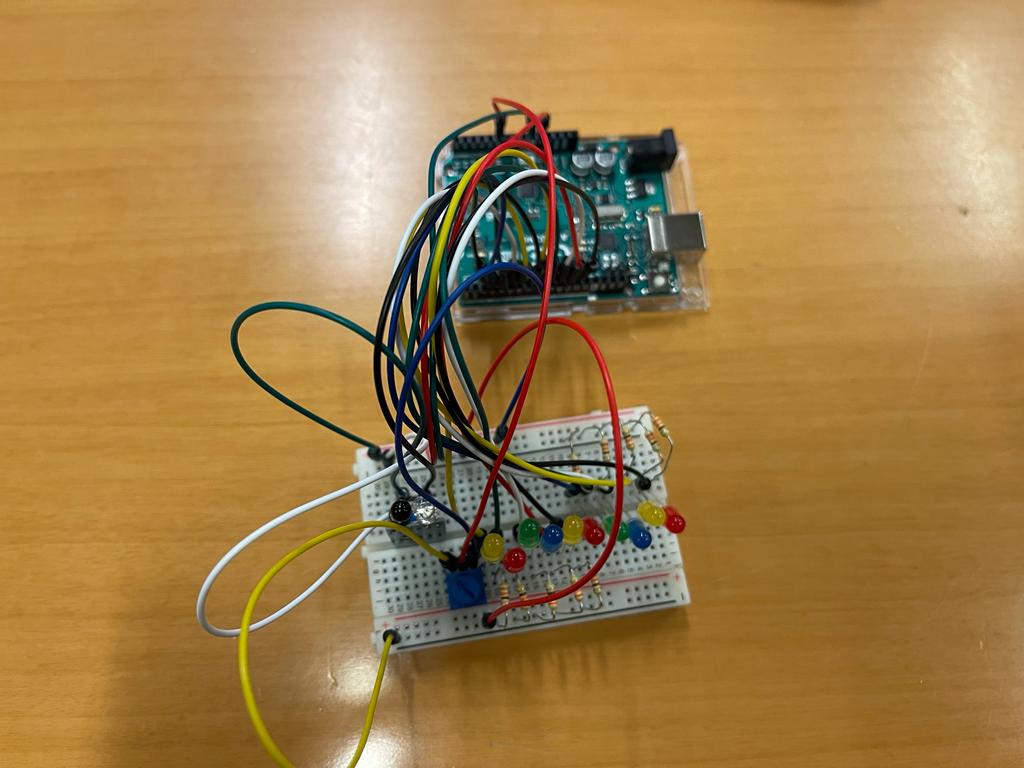
Then, all the 5 LEDs were connected with the resistors. I kept the colours different to get a nice colourful effect.
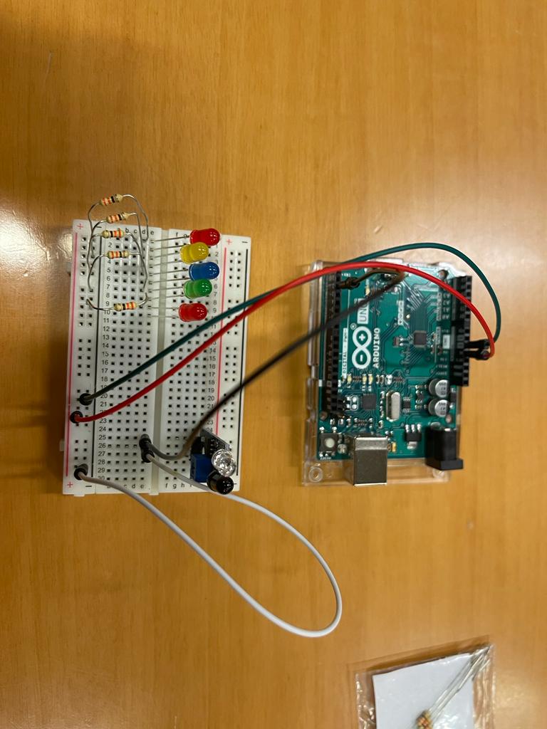
Moving forward, I connected all the LEDs and the digital sensor with Arduino and wrote a code to test all LEDs with my sensor. This way I was able to test all LEDs individually. The output video is shown.
// Shamma's code

// LED connected to 3,4,5,6,7 in arduino board
int gled = 3, b1led = 4, b2led = 5, yled = 6, rled = 7;

//sensor connected to pin 2 , the proximity sensor
int sensor = 2;

// initialize count variable to zero
int count = 0;

void setup()
{
  //All leds are being configured as an output and sensor is configured as an input because we read from it
  pinMode(gled, OUTPUT);pinMode(b1led, OUTPUT);
  pinMode(b2led, OUTPUT);pinMode(yled, OUTPUT);
  pinMode(rled, OUTPUT);
  pinMode(sensor,INPUT);

  //by default, I am switching all the leds off,
  //even if I remove those, code will work as my count is zero
  digitalWrite(gled,LOW);digitalWrite(b1led,LOW);
  digitalWrite(b2led,LOW);digitalWrite(yled,LOW);
  digitalWrite(rled,LOW);
}


void loop()
//reading if proximity sensor is low, then I will increment count variable by one

{
  //Once I place the hand, the count variable will switch from zero to 1,2,3,4,5,6
  //One is off, while next is on
  if(digitalRead(sensor)==LOW)
  {
    count = count + 1;

    //I use 5 LEDS, so I put 6 to restart the count
    if(count == 6)
    {
      count = 0;
    }
  }

// IF CONDITION for each LED on the mother board
  if(count == 0)
  {
    digitalWrite(gled,LOW);digitalWrite(b1led,LOW);
    digitalWrite(b2led,LOW);digitalWrite(yled,LOW);
    digitalWrite(rled,LOW);
  }
  else if(count == 1)
  {
    digitalWrite(gled,HIGH);digitalWrite(b1led,LOW);
    digitalWrite(b2led,LOW);digitalWrite(yled,LOW);
    digitalWrite(rled,LOW);
  }
  else if(count == 2)
  {
    digitalWrite(gled,LOW);digitalWrite(b1led,HIGH);
    digitalWrite(b2led,LOW);digitalWrite(yled,LOW);
    digitalWrite(rled,LOW);
  }
  else if(count == 3)
  {
    digitalWrite(gled,LOW);digitalWrite(b1led,LOW);
    digitalWrite(b2led,HIGH);digitalWrite(yled,LOW);
    digitalWrite(rled,LOW);
  }
  else if(count == 4)
  {
    digitalWrite(gled,LOW);digitalWrite(b1led,LOW);
    digitalWrite(b2led,LOW);digitalWrite(yled,HIGH);
    digitalWrite(rled,LOW);
  }
  else if(count == 5)
  {
    digitalWrite(gled,LOW);digitalWrite(b1led,LOW);
    digitalWrite(b2led,LOW);digitalWrite(yled,LOW);
    digitalWrite(rled,HIGH);
  }
  // once I place my hand, this delay will stop down the program
  delay(500);
}
After successfully completing the digital sensor, I worked on analog sensor and chose potentiometer. So, another 5 LEDs were added which would be controlled via analog sensor.
Just to be double sure that all LEDs were connected properly, I wrote a small test LEDs code. This ensured that the wiring was properly done with no errors. The output was as following:
//
int gled = 3, b1led = 4, b2led = 5, yled = 6, rled = 7;
int sensor = 2;
int count = 0;

void setup()
{
  pinMode(gled, OUTPUT);pinMode(b1led, OUTPUT);
  pinMode(b2led, OUTPUT);pinMode(yled, OUTPUT);
  pinMode(rled, OUTPUT);
  pinMode(sensor,INPUT);

  digitalWrite(gled,LOW);digitalWrite(b1led,LOW);
  digitalWrite(b2led,LOW);digitalWrite(yled,LOW);
  digitalWrite(rled,LOW);
}

void loop()
{
  if(digitalRead(sensor)==LOW)
  {
    count = count + 1;
    if(count == 6)
    {
      count = 0;
    }
  }

// only difference is that when one lights up, the other follows without switching off
  if(count == 0)
  {
    digitalWrite(gled,LOW);digitalWrite(b1led,LOW);
    digitalWrite(b2led,LOW);digitalWrite(yled,LOW);
    digitalWrite(rled,LOW);
  }
  else if(count == 1)
  {
    digitalWrite(gled,HIGH);digitalWrite(b1led,LOW);
    digitalWrite(b2led,LOW);digitalWrite(yled,LOW);
    digitalWrite(rled,LOW);
  }
  else if(count == 2)
  {
    digitalWrite(gled,HIGH);digitalWrite(b1led,HIGH);
    digitalWrite(b2led,LOW);digitalWrite(yled,LOW);
    digitalWrite(rled,LOW);
  }
  else if(count == 3)
  {
    digitalWrite(gled,HIGH);digitalWrite(b1led,HIGH);
    digitalWrite(b2led,HIGH);digitalWrite(yled,LOW);
    digitalWrite(rled,LOW);
  }
  else if(count == 4)
  {
    digitalWrite(gled,HIGH);digitalWrite(b1led,HIGH);
    digitalWrite(b2led,HIGH);digitalWrite(yled,HIGH);
    digitalWrite(rled,LOW);
  }
  else if(count == 5)
  {
    digitalWrite(gled,HIGH);digitalWrite(b1led,HIGH);
    digitalWrite(b2led,HIGH);digitalWrite(yled,HIGH);
    digitalWrite(rled,HIGH);
  }
  delay(500);
}
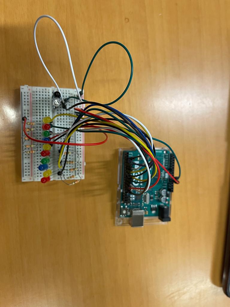
Finally, I added my analog sensor, the potentiometer in the circuit. It had 3 terminals out of which the corner ones were power rails and the middle one was the analog output which was connected to the analog input 0.
I wrote another small code to test only the analog sensor which turned the 5 LEDs dedicated for analog sensor one by one like shown.
// C++ code
//
int gled = 3, b1led = 4, b2led = 5, yled = 6, rled = 7;
//added the other 5 leds which will be used for my analog
int g2led = 8, b3led = 9, b4led = 10, y2led = 11, r2led = 12;
int digital_sensor = 2;
//declared the analog sensor
int analog_sensor = A0;
int count = 0;

void setup()
// all ten leds are configured as outputs
{
  pinMode(gled, OUTPUT);pinMode(b1led, OUTPUT);
  pinMode(b2led, OUTPUT);pinMode(yled, OUTPUT);
  pinMode(rled, OUTPUT);

  pinMode(digital_sensor,INPUT);

  pinMode(g2led, OUTPUT);pinMode(b3led, OUTPUT);
  pinMode(b4led, OUTPUT);pinMode(y2led, OUTPUT);
  pinMode(r2led, OUTPUT);

 // All 10 leds will be turned off

  digitalWrite(gled,LOW);digitalWrite(b1led,LOW);
  digitalWrite(b2led,LOW);digitalWrite(yled,LOW);
  digitalWrite(rled,LOW);

  digitalWrite(g2led,LOW);digitalWrite(b3led,LOW);
  digitalWrite(b4led,LOW);digitalWrite(y2led,LOW);
  digitalWrite(r2led,LOW);
}

void loop()
{
  // Analog Sensor Code
  // Reading the value from the analog sensor and storing it in the variable count
  int count = analogRead(analog_sensor);

// I divided 1024 by 5 as I have 5 leds and took the range from one switch to another
  if(count<10)
  {
    digitalWrite(g2led,LOW);digitalWrite(b3led,LOW);    digitalWrite(b4led,LOW);digitalWrite(y2led,LOW);    digitalWrite(r2led,LOW);
  }
  //
  else if(count>=10 && count<210)
  {
    digitalWrite(g2led,HIGH);digitalWrite(b3led,LOW);  digitalWrite(b4led,LOW);digitalWrite(y2led,LOW);    digitalWrite(r2led,LOW);
  }
  else if(count>=210 && count<410)
  {
    digitalWrite(g2led,HIGH);digitalWrite(b3led,HIGH);  digitalWrite(b4led,LOW);digitalWrite(y2led,LOW);    digitalWrite(r2led,LOW);
  }
  else if(count>=410 && count<610)
  {
    digitalWrite(g2led,HIGH);digitalWrite(b3led,HIGH);  digitalWrite(b4led,HIGH);digitalWrite(y2led,LOW);    digitalWrite(r2led,LOW);
  }
  else if(count>=610 && count<810)
  {
    digitalWrite(g2led,HIGH);digitalWrite(b3led,HIGH);  digitalWrite(b4led,HIGH);digitalWrite(y2led,HIGH);    digitalWrite(r2led,LOW);
  }
  else if(count>810)
  {
    digitalWrite(g2led,HIGH);digitalWrite(b3led,HIGH);  digitalWrite(b4led,HIGH);digitalWrite(y2led,HIGH);    digitalWrite(r2led,HIGH);
  }

//  // Digital Sensor Code
//
//  if(digitalRead(digital_sensor)==LOW)
//  {
//    count = count + 1;
//    if(count == 6)
//    {
//      count = 0;
//    }
//  }
//
//  if(count == 0)
//  {
//    digitalWrite(gled,LOW);digitalWrite(b1led,LOW);
//    digitalWrite(b2led,LOW);digitalWrite(yled,LOW);
//    digitalWrite(rled,LOW);
//  }
//  else if(count == 1)
//  {
//    digitalWrite(gled,HIGH);digitalWrite(b1led,LOW);
//    digitalWrite(b2led,LOW);digitalWrite(yled,LOW);
//    digitalWrite(rled,LOW);
//  }
//  else if(count == 2)
//  {
//    digitalWrite(gled,HIGH);digitalWrite(b1led,HIGH);
//    digitalWrite(b2led,LOW);digitalWrite(yled,LOW);
//    digitalWrite(rled,LOW);
//  }
//  else if(count == 3)
//  {
//    digitalWrite(gled,HIGH);digitalWrite(b1led,HIGH);
//    digitalWrite(b2led,HIGH);digitalWrite(yled,LOW);
//    digitalWrite(rled,LOW);
//  }
//  else if(count == 4)
//  {
//    digitalWrite(gled,HIGH);digitalWrite(b1led,HIGH);
//    digitalWrite(b2led,HIGH);digitalWrite(yled,HIGH);
//    digitalWrite(rled,LOW);
//  }
//  else if(count == 5)
//  {
//    digitalWrite(gled,HIGH);digitalWrite(b1led,HIGH);
//    digitalWrite(b2led,HIGH);digitalWrite(yled,HIGH);
//    digitalWrite(rled,HIGH);
//  }
  delay(500);
}
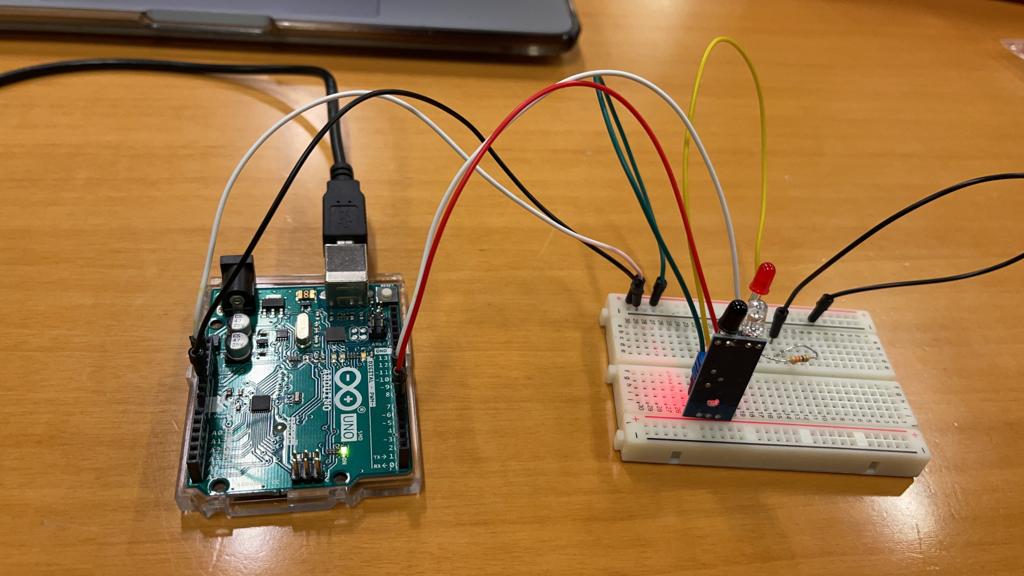
At last, I integrated the digital sensor and analog sensor code in one final code and I could control all 10 LEDs using different types of sensors.
// C++ code
// This is a combination of code 2 and 3 , both the proximity sensor and the analog which is the potentiometer
//Digital and analog sensor

int gled = 3, b1led = 4, b2led = 5, yled = 6, rled = 7;
int g2led = 8, b3led = 9, b4led = 10, y2led = 11, r2led = 12;
int digital_sensor = 2;
int analog_sensor = A0;
int count = 0,count2 = 0;

void setup()
{
  pinMode(gled, OUTPUT);pinMode(b1led, OUTPUT);  pinMode(b2led, OUTPUT);pinMode(yled, OUTPUT);  pinMode(rled, OUTPUT);
  pinMode(digital_sensor,INPUT_PULLUP);
  pinMode(g2led, OUTPUT);pinMode(b3led, OUTPUT);    pinMode(b4led, OUTPUT);pinMode(y2led, OUTPUT);  pinMode(r2led, OUTPUT);
  digitalWrite(gled,LOW);digitalWrite(b1led,LOW);  digitalWrite(b2led,LOW);digitalWrite(yled,LOW);  digitalWrite(rled,LOW);
  digitalWrite(g2led,LOW);digitalWrite(b3led,LOW);  digitalWrite(b4led,LOW);digitalWrite(y2led,LOW);  digitalWrite(r2led,LOW);
}

void loop()
{
  // Analog Sensor Code
  int count = analogRead(analog_sensor);

  if(count<10)
  {
    digitalWrite(g2led,LOW);digitalWrite(b3led,LOW);    digitalWrite(b4led,LOW);digitalWrite(y2led,LOW);    digitalWrite(r2led,LOW);
  }
  else if(count>=10 && count<210)
  {
    digitalWrite(g2led,HIGH);digitalWrite(b3led,LOW);  digitalWrite(b4led,LOW);digitalWrite(y2led,LOW);    digitalWrite(r2led,LOW);
  }
  else if(count>=210 && count<410)
  {
    digitalWrite(g2led,HIGH);digitalWrite(b3led,HIGH);  digitalWrite(b4led,LOW);digitalWrite(y2led,LOW);    digitalWrite(r2led,LOW);
  }
  else if(count>=410 && count<610)
  {
    digitalWrite(g2led,HIGH);digitalWrite(b3led,HIGH);  digitalWrite(b4led,HIGH);digitalWrite(y2led,LOW);    digitalWrite(r2led,LOW);
  }
  else if(count>=610 && count<810)
  {
    digitalWrite(g2led,HIGH);digitalWrite(b3led,HIGH);  digitalWrite(b4led,HIGH);digitalWrite(y2led,HIGH);    digitalWrite(r2led,LOW);
  }
  else if(count>810)
  {
    digitalWrite(g2led,HIGH);digitalWrite(b3led,HIGH);  digitalWrite(b4led,HIGH);digitalWrite(y2led,HIGH);    digitalWrite(r2led,HIGH);
  }

  // Digital Sensor Code

  if(digitalRead(digital_sensor)==LOW)
  {
    count2 = count2 + 1;
    if(count2 == 6)
    {
      count2 = 0;
    }
  }

  if(count2 == 0)
  {
    digitalWrite(gled,LOW);digitalWrite(b1led,LOW);
    digitalWrite(b2led,LOW);digitalWrite(yled,LOW);
    digitalWrite(rled,LOW);
  }
  else if(count2 == 1)
  {
    digitalWrite(gled,HIGH);digitalWrite(b1led,LOW);
    digitalWrite(b2led,LOW);digitalWrite(yled,LOW);
    digitalWrite(rled,LOW);
  }
  else if(count2 == 2)
  {
    digitalWrite(gled,HIGH);digitalWrite(b1led,HIGH);
    digitalWrite(b2led,LOW);digitalWrite(yled,LOW);
    digitalWrite(rled,LOW);
  }
  else if(count2 == 3)
  {
    digitalWrite(gled,HIGH);digitalWrite(b1led,HIGH);
    digitalWrite(b2led,HIGH);digitalWrite(yled,LOW);
    digitalWrite(rled,LOW);
  }
  else if(count2 == 4)
  {
    digitalWrite(gled,HIGH);digitalWrite(b1led,HIGH);
    digitalWrite(b2led,HIGH);digitalWrite(yled,HIGH);
    digitalWrite(rled,LOW);
  }
  else if(count2 == 5)
  {
    digitalWrite(gled,HIGH);digitalWrite(b1led,HIGH);
    digitalWrite(b2led,HIGH);digitalWrite(yled,HIGH);
    digitalWrite(rled,HIGH);
  }
  delay(500);
}
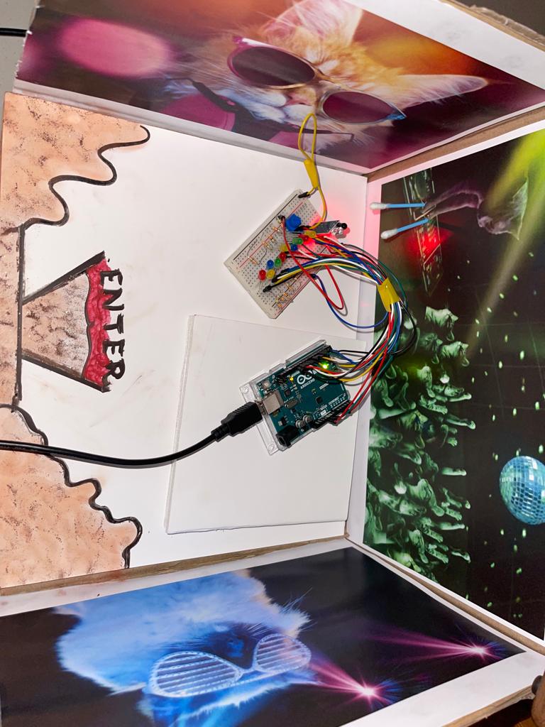
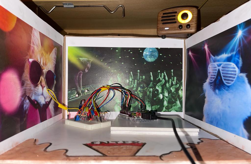
Just to add a little spice, I decided to cut down a cartoon box I found that is recycled and turn it into a space for cats to party. I did that by printing a couple of images, using a card board to give definition in terms of the party stage by adding a couple of card board together. Then, I used cotton bods as they will act as the cat paws which will trigger the proximity sensor when being moved on top of it. Later, I did not have any markers to draw the entrance of the party, so I used some makeup powders and eyeliner that I had, so excuse me for the mess. I also added a small radio I had on top of the box so I can run inside it a little fun cat song. At last, I placed the Arduino inside the cat space party to make the experience more real.

CONCLUSION:
The experience with this assignment has opened my eyes to the use of different sensors and how to interface them with Arduino. By being able to control LEDs using analog and digital sensors, although it’s a simple thing, it made me more enthusiastic about the more interesting applications that is to come.