The prompt for this week’s assignment is to make a musical instrument using digital sensors and analog sensors from the Arduino kit. But before getting into it:
Disclaimer: I know next to nothing about music. My project focuses much more on the technical side of it than the musical or aesthetic side.
My main idea was to make a piano-like device that can play different notes when different switches are triggered. The main problem is that the Arduino kit is limited in the size of the breadboard as well as the availability of components. There are only four buttons and while using them for four notes is a good idea, I found it pretty limiting. I also imagined it would be difficult to use the switches if they were all on the same board. So I tried to come up with an idea on how to expand the instrument to a wider area while still putting all the controlling components on the board. After many days of brainstorming and experimenting, I have made an instrument that can play 21 notes using three buttons, one distance measuring sensor, and a few helping extra components (paper!).
Following is a short demo of my product. Please excuse the bad camerawork. I would have tried to play a legit song if not for the disclaimer (see above). The circuit and the code can be found at the end of the post.
Processes
I figured that I could use one of the sensors to control the sounds. Among the available sensors, the distance measuring sensor seemed to be the most suitable for my idea. And thus I mostly tinkered with it through examples I found online, like this tutorial. My main idea was to put a number of separators increasingly further away from the sensor so that each separator will trigger a certain note.
The first step was programming the Arduino. Following the tutorial I linked above, I was able to play different notes when I put a surface at different distances from the sensor. I made some adjustments to the parameters used in the original code so that the calculatedDistance returned is in centimeters instead of inches because imperial units do not make sense to me. I was also able to get inspiration from BlinkWithoutDelay in order to play a note one time for a short duration then stop until the next note is triggered, instead of having the sound played constantly.
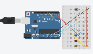
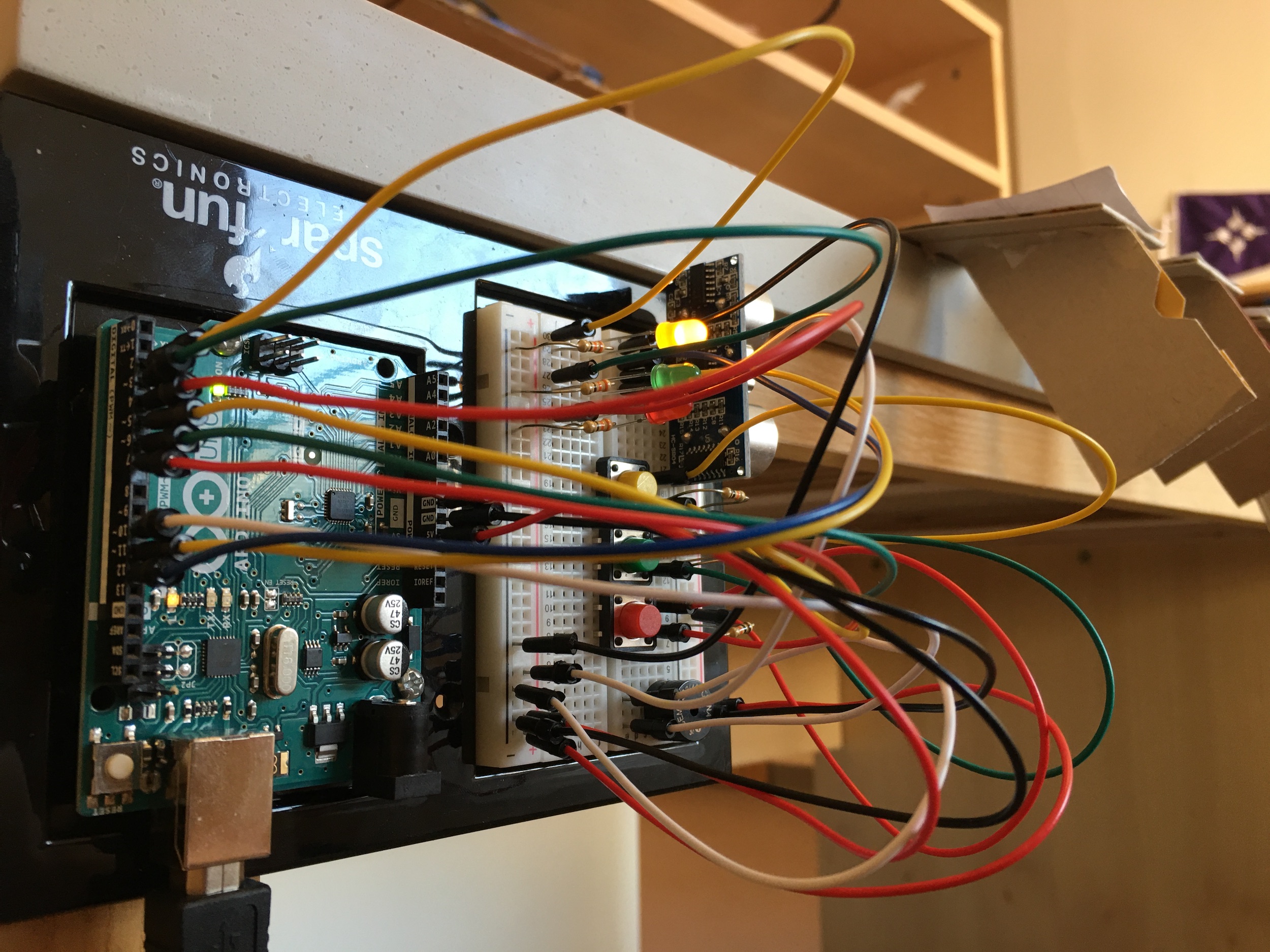
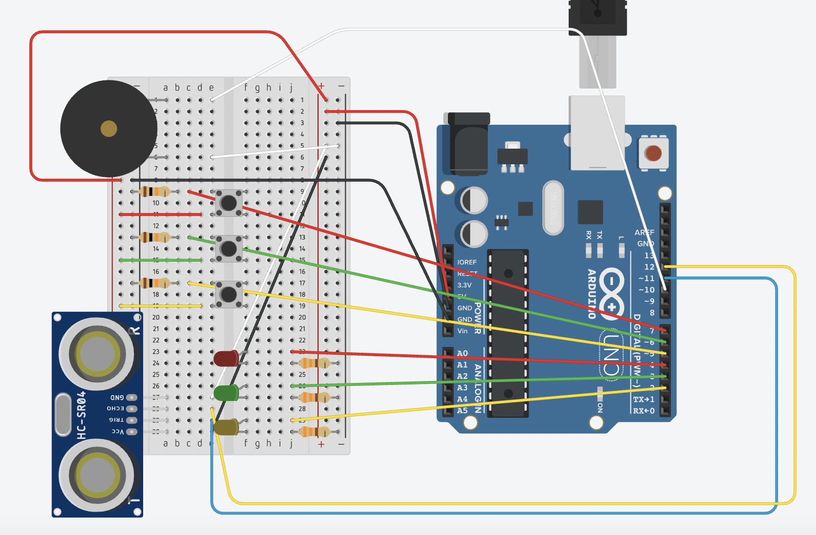
I originally planned to have 8 notes from C4 to C5, but as I was testing the board, I realized I could add more notes without having to increase the distances of the notes from the sensor. Instead, I added three buttons to the board, corresponding to three octaves (I hope I’m using the correct term here). Specifically, when no button is pressed or the yellow button is pressed, available notes are C4-B4. Similarly, green mode corresponds to C5-B5, and red mode corresponds to C6-B6. Theoretically, I could add one more blue button corresponding to one more octave, but I was running out of space on the breadboard and pins on the Arduino. In order to keep track and signify the current mode, I added three LEDs with the same colors as the buttons. The final circuit was pretty complicated due to the sheer number of jumper cables alone, so it took me a while to plug everything in correctly without one component messing up another.
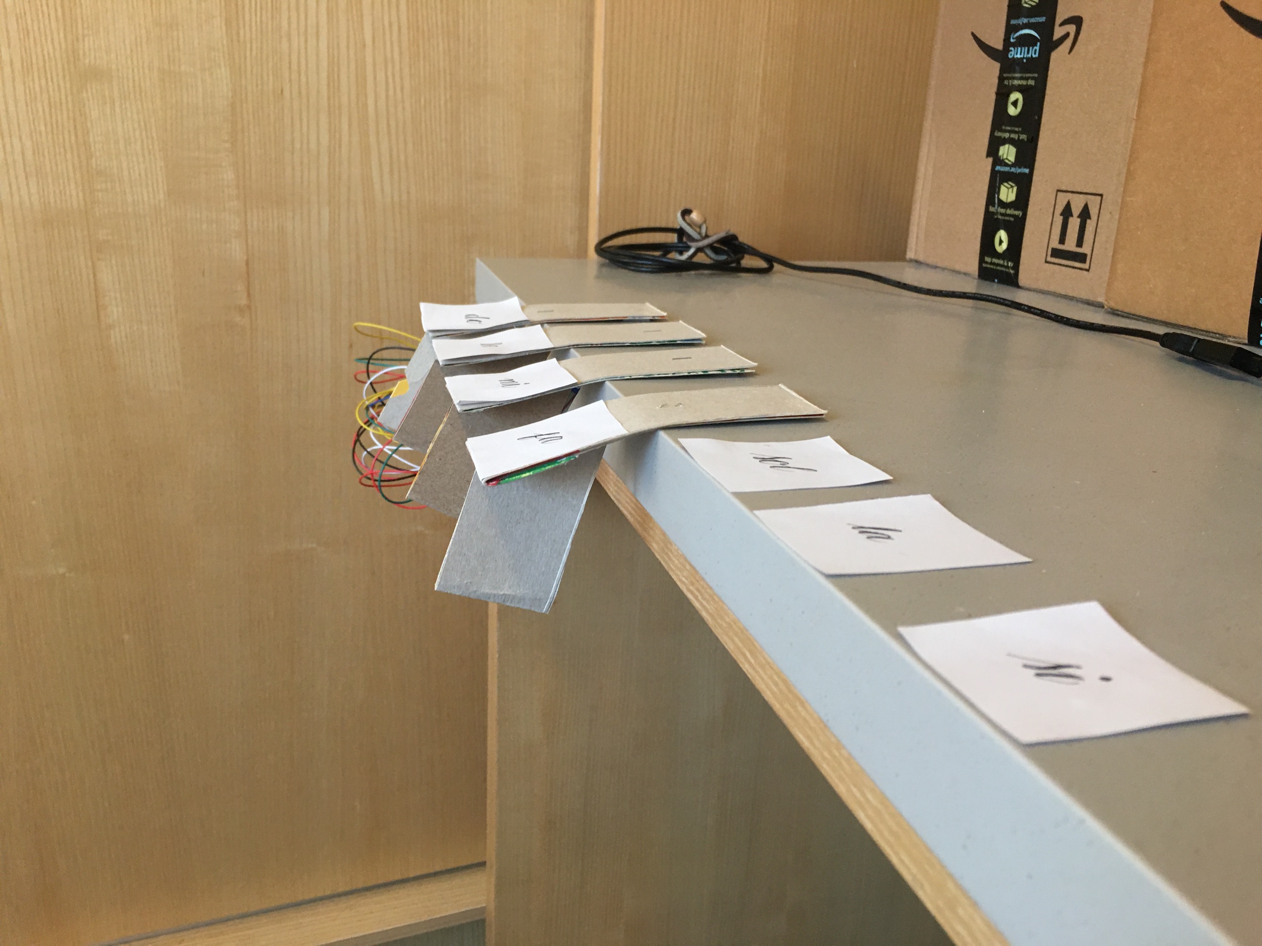
After finishing the board, I moved on to setting up the actual ‘keyboard’. The brainstorming behind this was pretty messy and took many days. I settled on improvising with cardboard. With limited resources, my final ‘keyboard’ was made out of old cereal box (hence the name of my project).
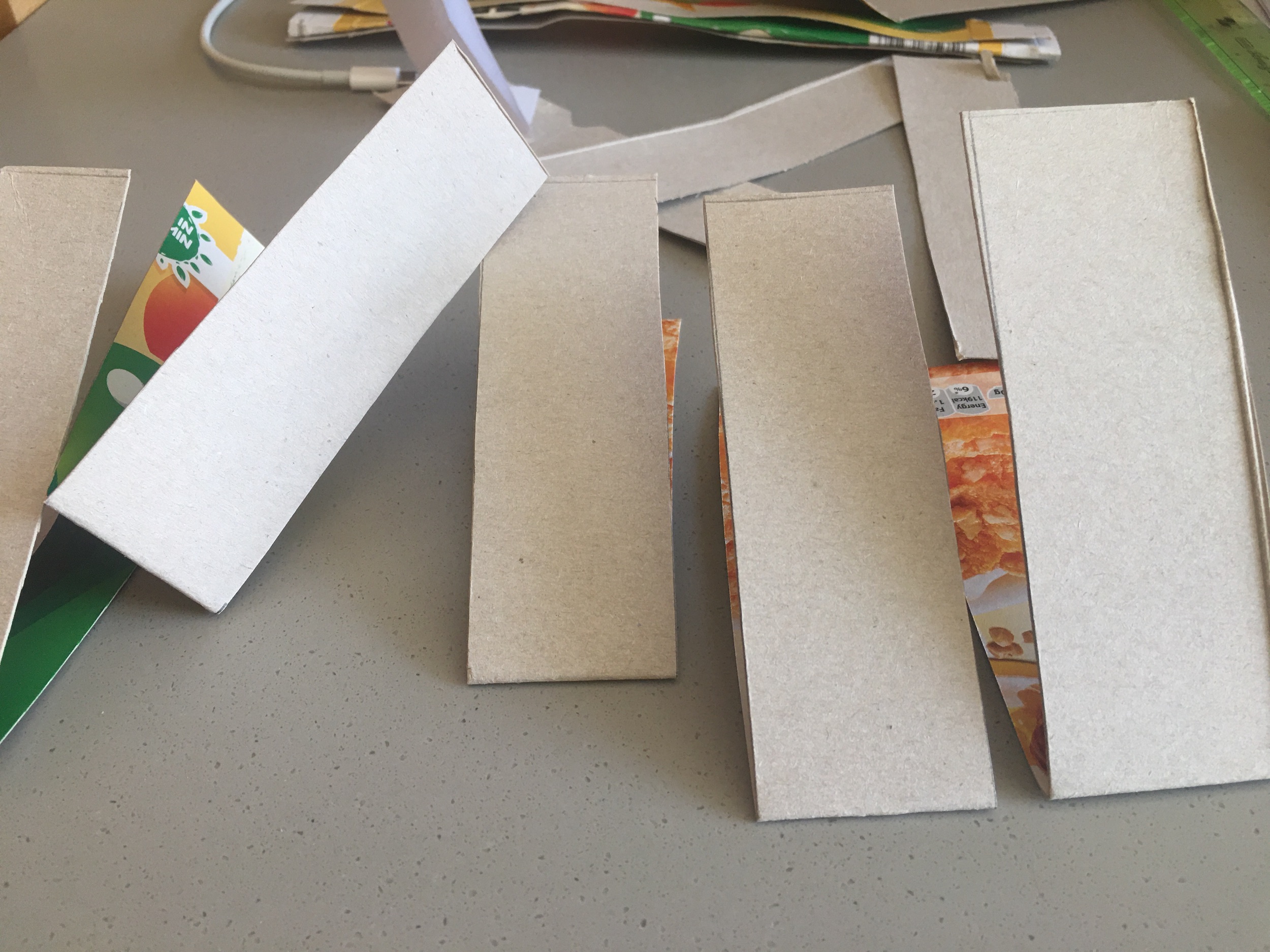
Making my cereal box piano keys
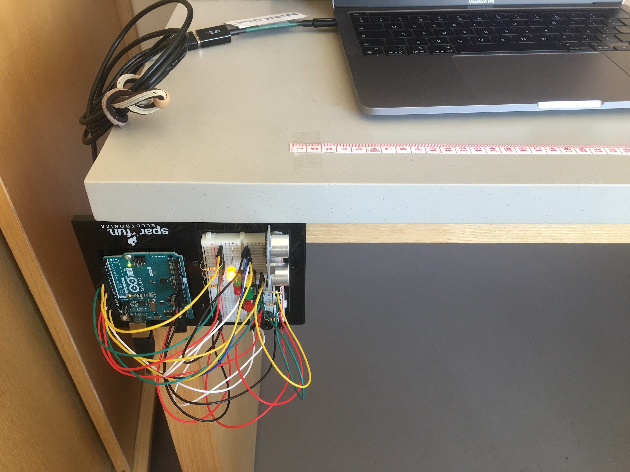
The final setup involved sticking the Arduino vertically to the desk and placing the ‘keys’ in the correct positions.
Problems
My biggest problem was that the readings from the sensor were relatively unstable. I experimented with it many times, but I didn’t manage to stabilize the analog input. Sometimes I put a static surface in front of the sensor from a fixed distance but the readings I got were fluctuating a lot. This proved to be a problem since the keys did not work quite smoothly as I wanted. As can be seen in the demo video, when I set up the last three keys in the same fashion, for some reason the distance returned was off by a very large margin.
What I learned
I learned a lot about the way the distance measuring sensor works. I also got the chance to solidify my understanding of the board and different circuit designs, since I needed to adjust the different components on the board and arrange them in such a way that one’s function does not result in another one’s non-function.
Circuit and code
#include "pitches.h"

const int trigPin = 11;
const int echoPin = 12;

int buttonPins[3] = {5, 6, 7}; // 5 = yellow, 6 = green, 7 = red
int currentButtonStates[3];
int previousButtonStates[3] = {LOW, LOW, LOW};
int ledPins[3] = {2, 3, 4}; // 2 = yellow, 3 = green, 4 = red
int ledStates[3] = {LOW, LOW, LOW};

int offset = 0;
int offsets[3] = {0, 7, 14};
float distance;

int previousNote = 8;

int notes[21] = {NOTE_C4, NOTE_D4, NOTE_E4, NOTE_F4, NOTE_G4, NOTE_A4, NOTE_B4, NOTE_C5, NOTE_D5, NOTE_E5, NOTE_F5, NOTE_G5, NOTE_A5, NOTE_B5, NOTE_C6, NOTE_D6, NOTE_E6, NOTE_F6, NOTE_G6, NOTE_A6, NOTE_B6};

void setup() {
  Serial.begin(9600);

  pinMode(trigPin, OUTPUT); // the trigger pin will output pulses of electricity
  pinMode(echoPin, INPUT); // the echo pin will measure the duration of pulses coming back from the distance sensor

  for (int i=0; i<3; i++) {
    pinMode(buttonPins[i], INPUT);
    pinMode(ledPins[i], OUTPUT);
  }
}

void loop() {
  // Buttons and LEDs
  for (int i=0; i<3; i++) {
    currentButtonStates[i] = digitalRead(buttonPins[i]);
    if (currentButtonStates[i] == HIGH && previousButtonStates[i] == LOW) {
      ledStates[0] = LOW;
      ledStates[1] = LOW;
      ledStates[2] = LOW;
      ledStates[i] = !ledStates[i];
      offset = offsets[i];
    }
    digitalWrite(ledPins[i], ledStates[i]);
    previousButtonStates[i] = currentButtonStates[i];
  }

  // Sound
  distance = getDistance();
  int currentNote = min(int(distance-10.0) / 7 + offset, 22);
  Serial.print(distance);
  Serial.print(" ");
  Serial.println(currentNote-offset);

  if (currentNote >= offset && currentNote < offset+7 && previousNote == 22) {
    tone(10, notes[currentNote], 300);
  }

  previousNote = currentNote;
  delay(50);
}

float getDistance() {
  float echoTime;
  float calculatedDistance;

  digitalWrite(trigPin, HIGH); // send out an ultrasonic pulse that's 10ms long
  delayMicroseconds(10);
  digitalWrite(trigPin, LOW);

  echoTime = pulseIn(echoPin, HIGH); // use the pulsein command to see how long it takes for the pulse to bounce back to the sensor

  calculatedDistance = echoTime / 58.0; // calculate the distance of the object that reflected the pulse (half the bounce time multiplied by the speed of sound)

  return calculatedDistance;
}